How to Make Long-Range Radios
This week took a long time. For future how-to-makers, start earlier than you think.
I was definitely excited for this week. I've wanted to do a LoRa project for a long time (I was considering it for my final project, but decided otherwise), so I used this week as an excuse to build some LoRa radios!
Working radio + SMD21E18 board
LoRa can send small amounts of data over long distances (up to 12 kilometers). From the Internet of Things Wiki: Developed by Semtech, LoRa is a spread spectrum modulation technique derived from chirp spread spectrum (CSS) technology. It allows high noise robustness, and so provides a rather long range (up to 10km) even with small power. However, it has low data rate of up to 50kbps because it uses Sub-GHz ISM bands. It has different parameters that can be determined to fix properties such as range, data rate, noise robustness.
With LoRa we can send data over the LoRaWAN network (which I don't do in this week's project).
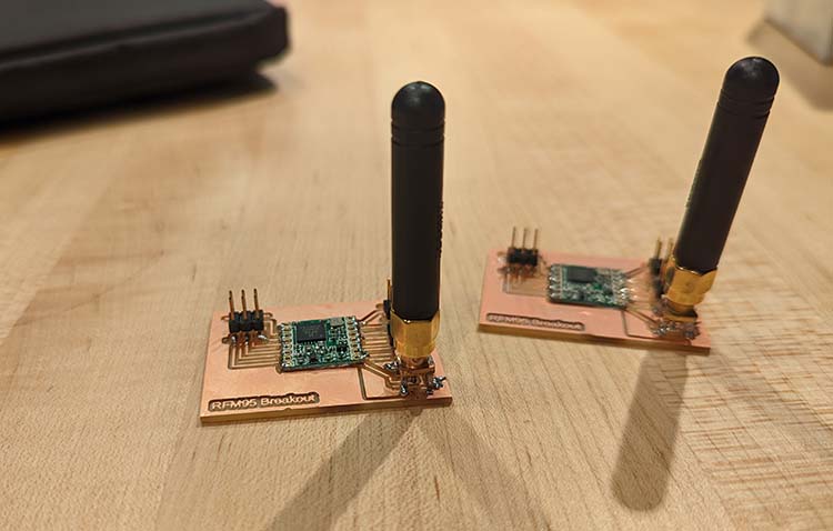
RFM95 Breakout Board (With Downloads)
There were three different LoRa boards available in the CBA shop, but the RFM95 seemed to be the most well-documented online, so I went with that one.
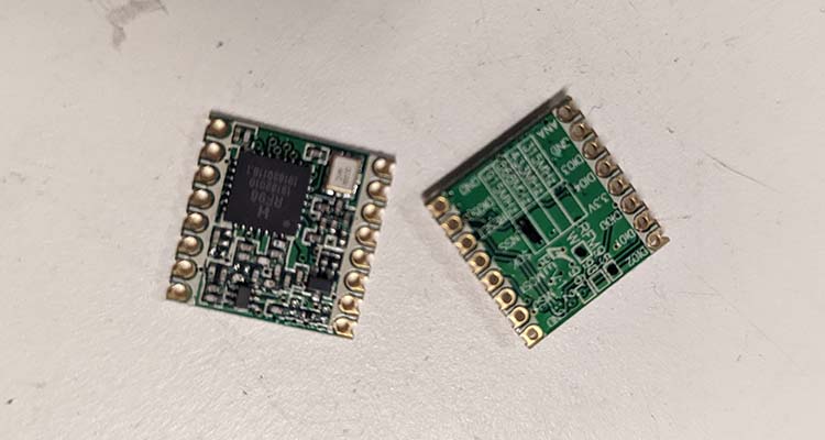
RFM-95 components
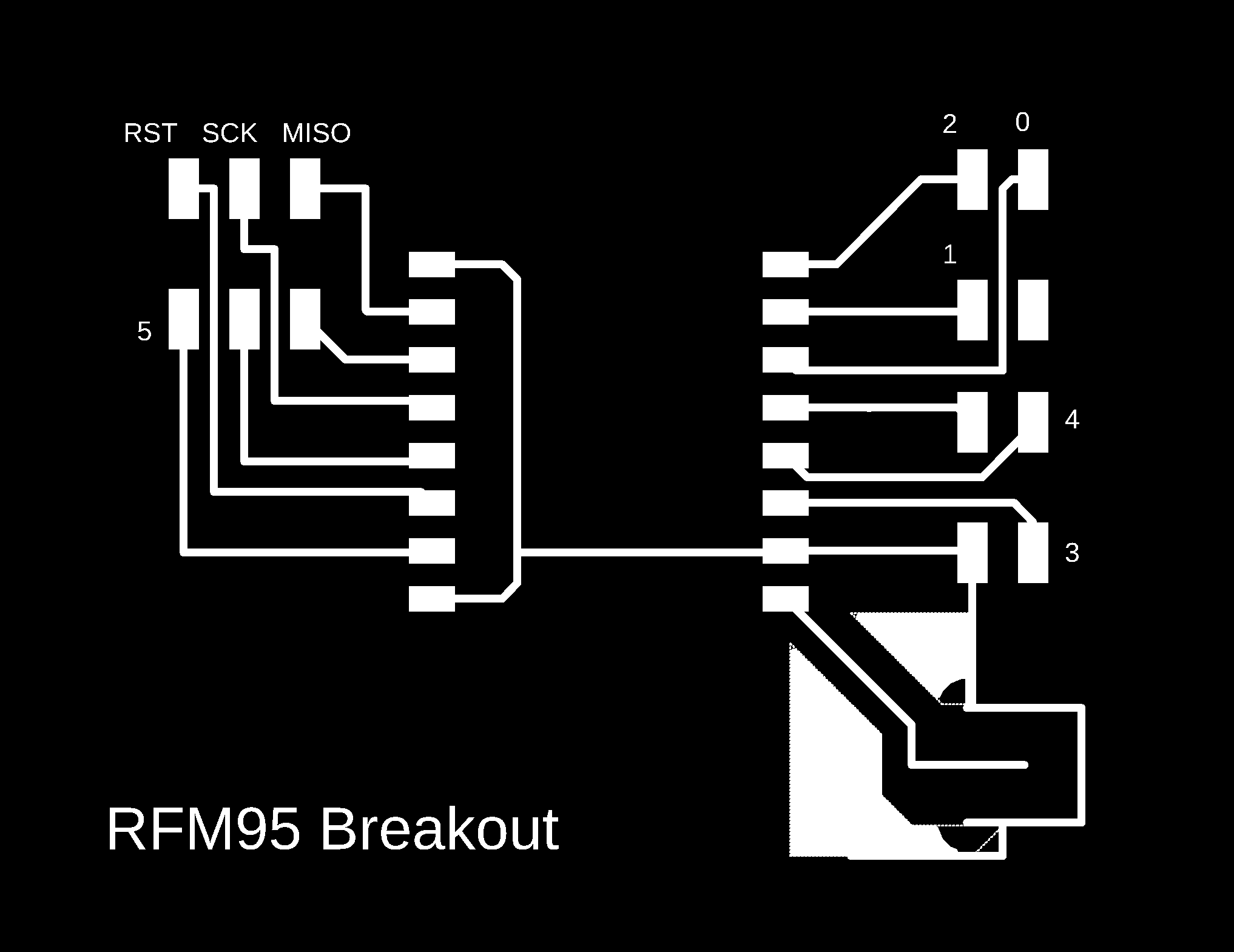
The pins on the board are non-standard, which makes it impossible to use pins out of the box to prototype. I designed and milled a breakout board with an antenna and pins to connect it to another chip. I couldn't find one online, so feel free to download and use this one.
Download:
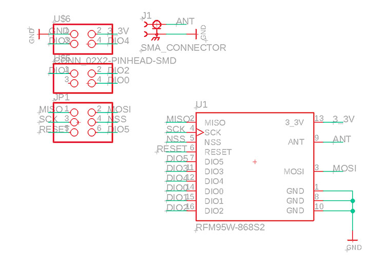
Breakout board schematic design
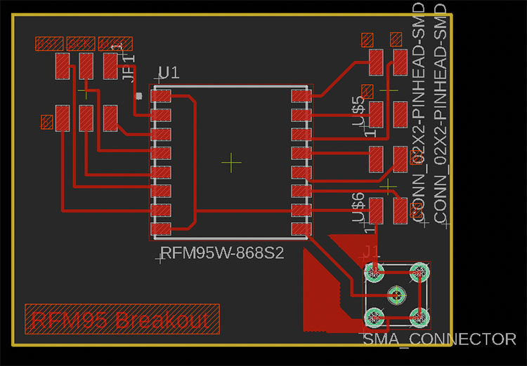
Breakout board pcb design
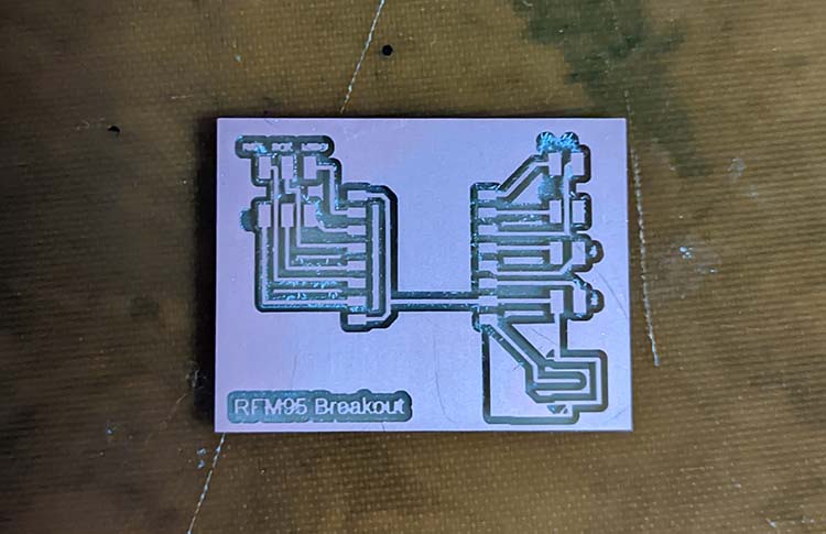
Milled board
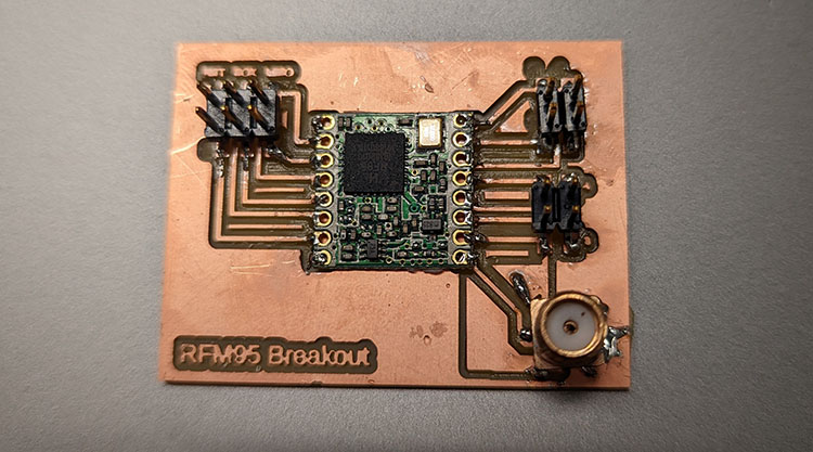
Assembled board
To get the antenna for the board, I took a different component from the CBA inventory and used a hot-air gun to desolder and remove the antennas.
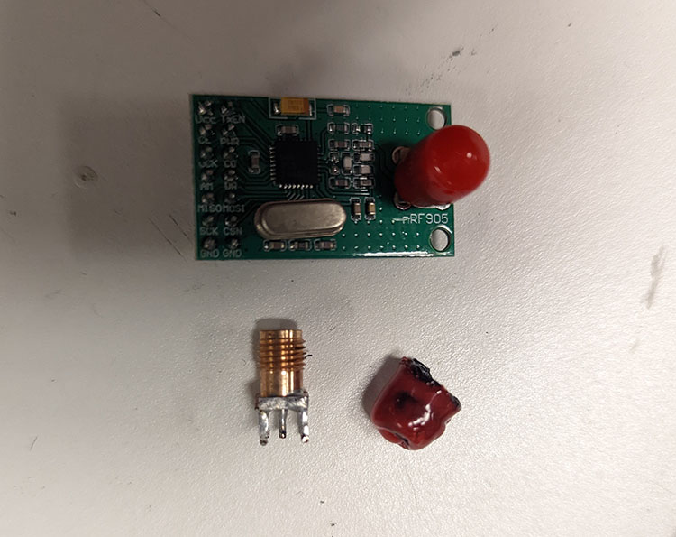
Antenna - on the board (top) and removed (bottom). I didn't realize I could take the red part off when I desoldered the first one...
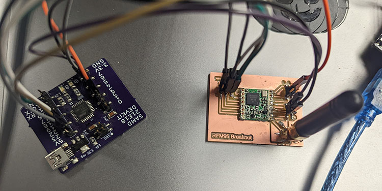
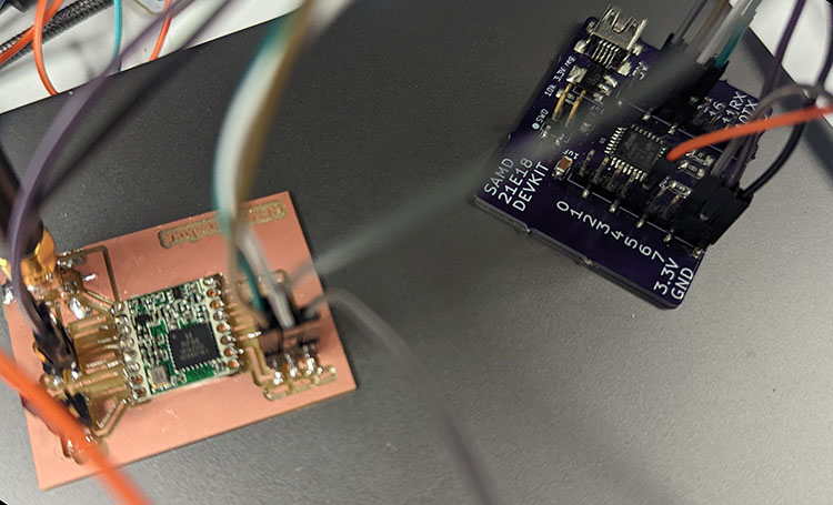
Connecting RFM95 + SMD21E
When connecting the boards, I used Quentin's dev board. When I designed my dev board, I didn't connect every pin, some of which were necessary for this project. I tried to solder a wire directly onto the chip, but it was unreliable.
To decode the pins, I switched between the Adafruit documentation and Quentin's MTM documentation for the pinouts with his bootloader.
- MISO → MISO (PIN 22)
- MOSI → MOSI (PIN 18)
- NSS → SS (PIN 23) (called CS on Adafruit)
- SCK → SCK (PIN 19) (called SCLK on Adafruit)
- DIO0 / IRQ / INT → Any pin with a Harware Interrupt, shown as a * under the INT column (PIN 4) (Called G0 on Adafruit)
- RESET → Any pin (PIN 7)
Image of the boards connected is below. When doing this project, you'll have to create two complete radios so they can communicate, otherwise I'm not sure how you would test that everything is working properly.
Code
The code below sends a message from one radio to a second. The second accepts the message and replies. That's it for now!
Install the Arduino RadioHead library to use the code examples below.
It's difficult to debug this code. If a packet doesn't send, there's no information available as to why. I ended up having issues with my soldering on the breakout board, once that was fixed I was able to send messages back and forth between my two radios.
LoRa Ping
            //smd2118e


            #include <RH_RF95.h>


            #define LED LED_BUILTIN


            #define RF95_CS 23

            #define RF95_INT 4

            #define RF95_RST 7


            #define RF95_FREQ 915.0


            RH_RF95 rf95(RF95_CS, RF95_INT);


            uint8_t data[RH_RF95_MAX_MESSAGE_LEN];


            void setup() {

                Serial.begin(9600);


                while (!rf95.init()) {

                    Serial.println("LoRas radio init failed");

                    delay (100);

                    digitalWrite(RF95_RST, LOW);

                }


                digitalWrite(RF95_RST, LOW);

                delay(20);

                digitalWrite(RF95_RST, HIGH);

                delay(20);


                rf95.setFrequency(RF95_FREQ);

            }


            int16_t packetnum = 0;  // packet counter, we increment per xmission

            void loop() {

                rf95.printRegisters();


                Serial.println("Sending to rf95_server");

                // Send a message to rf95_server


                char radiopacket[20] = "Hello World #      ";

                itoa(packetnum++, radiopacket+13, 10);

                Serial.print("Sending "); Serial.println(radiopacket);

                radiopacket[19] = 0;


                Serial.println("Sending..."); delay(10);

                rf95.send((uint8_t *)radiopacket, 20);

                rf95.printRegisters();


                Serial.println("Waiting for packet to complete..."); delay(10);

                rf95.waitPacketSent();

                // Now wait for a reply

                uint8_t buf[RH_RF95_MAX_MESSAGE_LEN];

                uint8_t len = sizeof(buf);


                Serial.println("Waiting for reply..."); delay(10);

                if (rf95.waitAvailableTimeout(1000)) {

                    // Should be a reply message for us now

                    if (rf95.recv(buf, &len)) {

                        Serial.print("Got reply: ");

                        Serial.println((char*)buf);

                        Serial.print("RSSI: ");

                        Serial.println(rf95.lastRssi(), DEC);

                    }

                    else {

                        Serial.println("Receive failed");

                    }

                }

                else {

                    Serial.println("No reply, is there a listener around?");

                }

                delay(1000);

            }
LoRa Echo
            //uno


            #include <RH_RF95.h>


            #define RF95_CS 10

            #define RF95_INT 2

            #define RF95_RST 5


            #define RF95_FREQ 915.0


            RH_RF95 rf95(RF95_CS, RF95_INT);


            uint8_t data[RH_RF95_MAX_MESSAGE_LEN];


            void setup() {


                pinMode(RF95_RST, OUTPUT);

                digitalWrite(RF95_RST, HIGH);

                delay(10);

                digitalWrite(RF95_RST, LOW);

                delay(10);

                digitalWrite(RF95_RST, HIGH);

                delay(10);


                Serial.begin(9600);


                rf95.init();

                rf95.setFrequency(RF95_FREQ);

            }


            void loop() {

                Serial.println("loop starts");

                if (!rf95.available()) {

                    return;

                }


                uint8_t len = sizeof(data);


                Serial.println("receive data 1");

                if (!rf95.recv(data, &len)) {

                    return;

                }


                Serial.println("receive data 2");

                Serial.println((char*) data);


                rf95.send(data, len);

                rf95.waitPacketSent();

                Serial.println("Message sent back");

            }
Next Steps
After getting the example above to work, I designed two different boards. First, I designed a standalone LoRa + SMD21E18 board. Then, after some reading, I realized that I could program a LoRa radio with just an ESP-32 (and then I could send any data received to the web!). I started designing that board as well, but ended up running out of time.
Additionally, I'd like to extend these standalone boards to also include buttons and a screen so that they can be used to communicate without depending on a separate interface. To be continued!