Week 4: electronics design
This week's journey
I wasn't sure where to get started this week. I had used Eagle in previous weeks, so I opened that up, but wasn't sure exactly how to translate the material online into a new design.
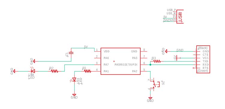
I found the examples in the Fab Fusion account which helped me get started. Using those as a guide, I designed a new board with an FTDI cable and USB connection for power.
Components used (from the Fab Fusion library):
- One 1uf capacitor
- Two LEDs
- One 4.99k resistor (for the UPDI connection)
- Two 1k resistors (for the LED connections)
- One ATTiny 412
- One FTDI Connection (1x6 pin connector)
- One USB Connection
I made a few different versions of the PCB document design before I got something working.
First, I made a version with the plan to create a snake with a USB as a tail. Those didn't go well, so I pivoted to a zeplin.
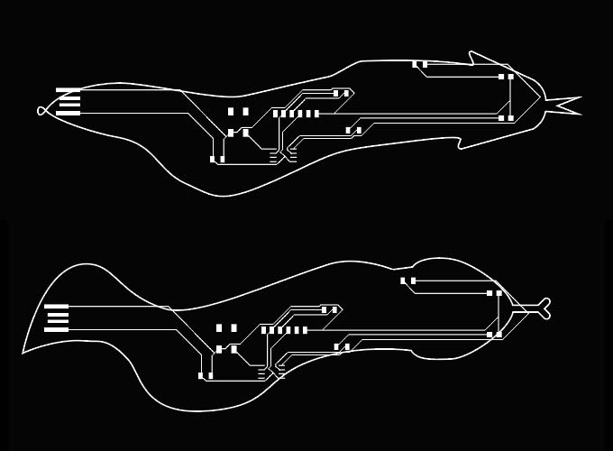
Failed snakes
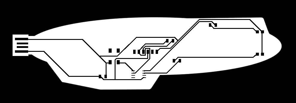
Zeplin
The zeplin looked good on paper (screen?), but I ran into issues when milling it. The traces were too long and got pulled off the board.
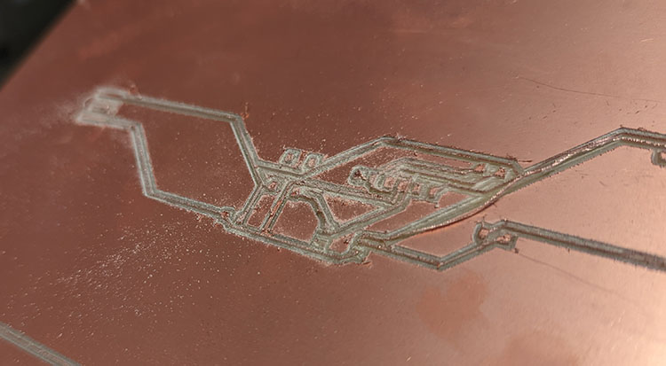
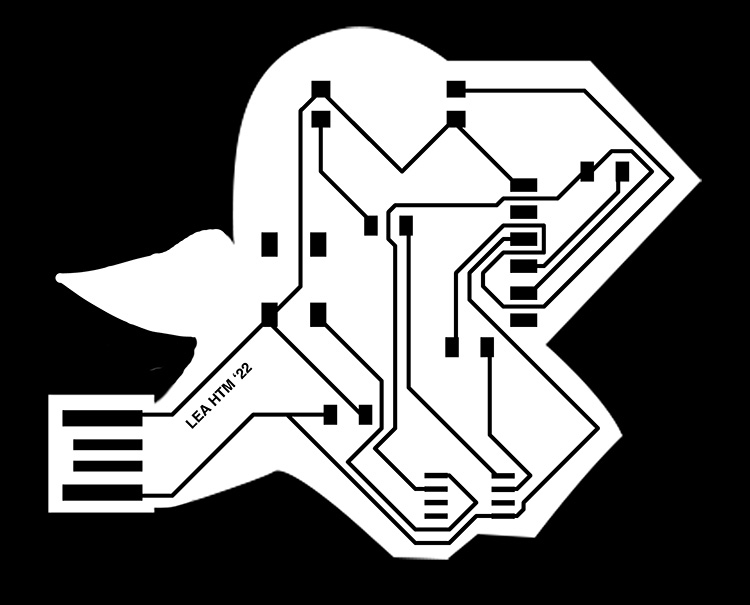
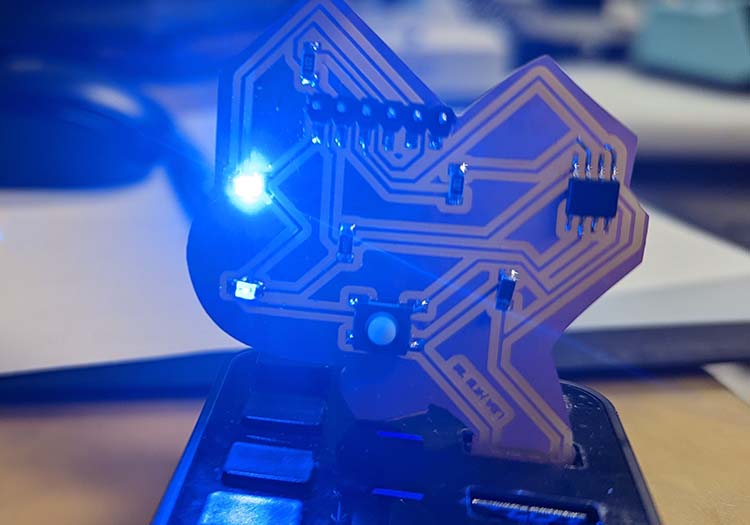
I pivoted again and turned my design into a parrot with glowing eyes.
After another poorly milled board, I learned that my DPI when exporting from Eagle should have been at ~1000 instead of 150.
After reading Neil's reply on Gitlab, I realized I had made a mistake designing my board to use an FTDI programmer. At that point it was Tuesday night at 8:19pm, and so instead of redesigning, milling, and soldering a new parrot, I took it as input for the next iteration.
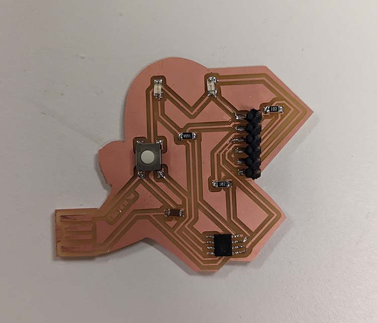
Here's the final parrot! I had to chop off its wing to fit in the USB slot :')
Despite having designed the circuit diagram I was reading, I believe I put my 4.9k resistor in the wrong place, making one eye less bright than the other. Or maybe the way I designed it was off from the start. Oh well, learnings for the next electronics project!