Week 6: embedded programming
I have no idea how much time I spent on this this week, but definitely above the 18 hours ;_;
Introduction
One possible final project I’m considering are IR-camera-sensing glasses that can protect biometric data from bad actors. I already had a working prototype from previous work I had done using breadboards and the Adafruit M0 Trinket board.
It checks the amount of IR light, and if it sensed enough that a camera might be close by, it would let the wearer know with a vibration and turn on IR lights to obscure their face.
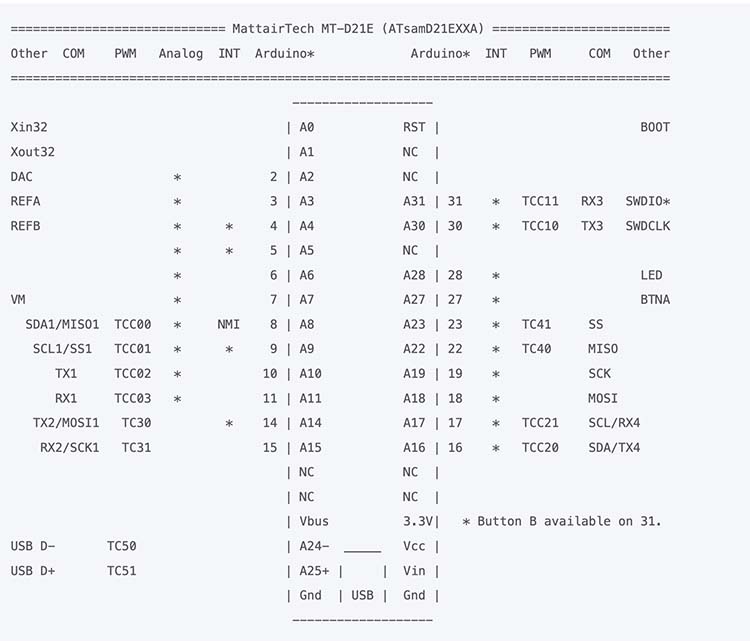
Reference 0
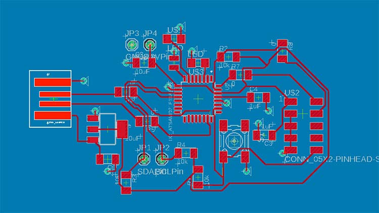
Building Board 1
I looked at the Trinket M0 Eagle Schematic to see which of the SMD21E18 pins corresponded with the M0 board pinouts. Then I built my board with a combination of that information and Jake’s ECAD Demo from last year.
I also plan to create a second, smaller board with the actual light sensor on it to go in the middle of the glasses, but am waiting on the SI1145 individual sensor component.
My previous prototype used an Arduino M0 Trinket Board, but I only wanted to reference the chip and create my own board with all my components on it. I compared the adafruit board pinouts with the chip pinouts, and set up my board in the same way (This would become a problem later).

Adafruit M0 Trinket Eagle Schematic
I had ongoing challenges finding the right components. The capacitors in the fab library I referenced were too big, as were my pins to connect to JTAG to install the bootloader. I pulled in the “correct” components by copying and pasting them from HTMAA MIT example boards in the Fusion account, since I wasn’t able to find them in the fab library.
I was using the back of my board as a ground plate with vias. I used the ones in the CBA lab, some went in well, others got squished. Rivets are small metal rings that get installed with a lever that pushes them into the hole in the board.
Board 1 with rivets installed
Okay, so now I have a board. Was it working? Unclear. I used a multimeter to check connections, specifically checking for continuity throughout my board.
A bunch of my rivets weren’t connected. I globbed solder on both sides, which seemed to fix it.
My other issue was the ridiculously small size of my USB to USB-c dongle. I cut the USB with scissors so it would fit – a very ugly solution. Other mistake: I soldered wires directly onto my board which was a huge mistake, they pulled my traces up and were terrible. I replaced them with standalone through-pins which were also terrible.
THEN I realized I had used a 5v converter by accident (there was no 3.3 in the shop and I just went by shape). I pulled it off my board carefully, a process that ripped up parts of my board. I went into the CBA lab to get a 3.3v converter from one of the drawers. I didn’t check and just trusted the label, huge mistake. It was another 5v converter. At that point I gave up, RIP board.
RIP board 1
Board 2
Okay, back to Eagle. I redesigned my board in a couple of hours and milled the new one. Quentin encouraged me not to use rivets this time. Okay, now it’s 11pm on Monday, I left the lab to head home. On the way there I see Quentin in the banana lounge, where he informs me I have two shorts. Next time I should set the mods width to 15.9mm instead of 16mm, since even with the recommended design rules my board ended up with these. I cut them apart with an exacto-knife before assembling the board.
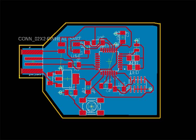
Board 2 design with rivets
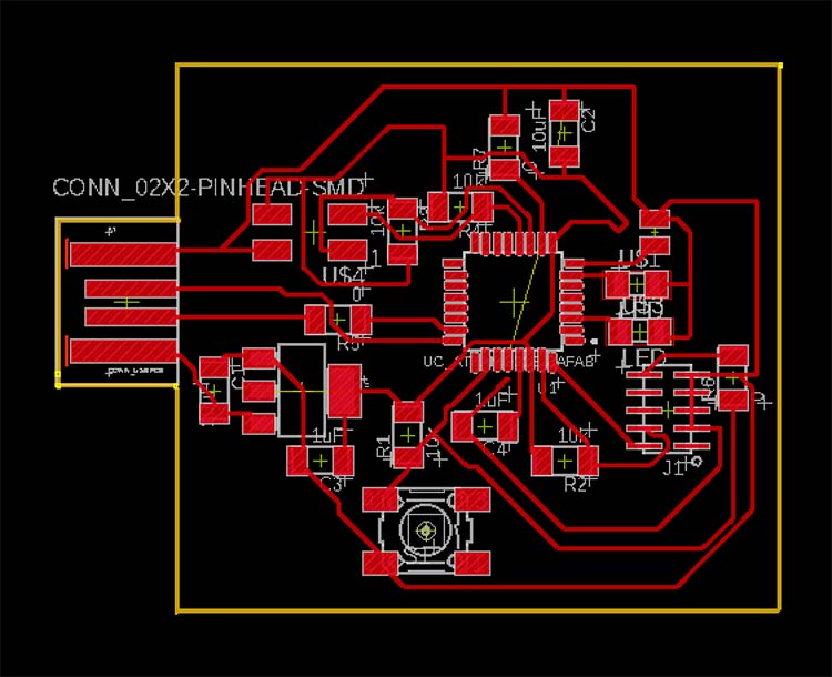
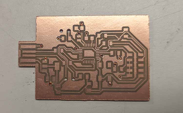
With rivets removed!
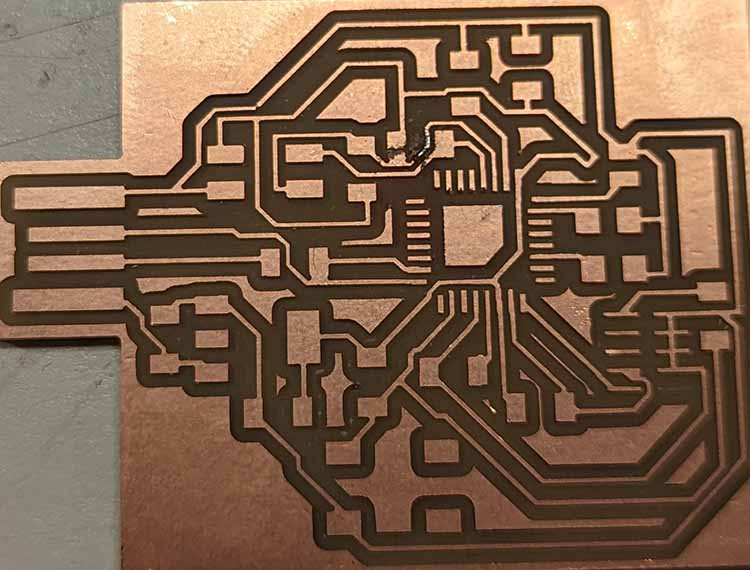
Board 2 freshly milled
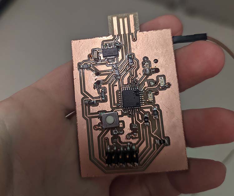
I assembled the board with my precious last 3.3v converter.
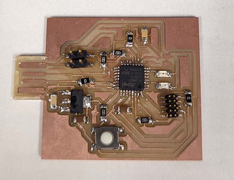
Board 2 assembled
Installing the bootloader was straightforward, I used the board script on the MTM site by connecting the board via JTAG.
At first after installing the bootloader and plugging the board into my laptop, my computer wasn’t reading that the board was connected. Miana explained that this was because the USB-3 dongle was expecting faster data exchange. I used a USB-2 dongle in the lab instead.
When I went to load the code I had previously prepared, everything crashed and I had to reinstall the bootloader on the chip. Okay, no worries. I ran blink code to make sure anything was working. No! The pinouts on the chip with this bootloader are different than the Adafruit version of the same chip. I update these based on the P#s on both diagrams, and the blink code worked!
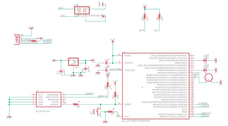
My Board Design
Bootloader Pinout re: MTM
Adafruit M0 Trinket Eagle Schematic
My other code kept crashing the chip. After isolating and running specific lines of code, I figured out that the crash was related to calling the SI1145 library when it wasn’t successfully set to anything.
I fixed this in the code, but the sensor still wasn’t sending data back to the chip. I used and oscilloscope to see if everything was connected properly. It was, but the SCL and SDA pins were staying at a solid 5V. Anthony helped me debug this, the Adafruit version of the chip and my chip with the MTM bootloader were using different I2C pins. We updated the SI1145 library to reference Wire1 instead of Wire on line 154 of Adafruit_SI1145.h, and FINALLY everything worked.
Code
        #include

        #include "Adafruit_SI1145.h"


        Adafruit_SI1145 uv = Adafruit_SI1145();


bool running = false;


void setup() {

    while (!Serial) ;


   if (! uv.begin()) {

      Serial.println("Didn't find Si1145");

      while (1);

   }


   if (uv.begin()) {

      running = true;

   }


     pinMode(2, OUTPUT);

    pinMode(6, OUTPUT);

   pinMode(7, OUTPUT);


}


void loop() {

   if (running) {

      float Vis = uv.readVisible();

      float IR = uv.readIR();

      float UVindex = uv.readUV();


      UVindex /= 100.0;


      if(IR > 274) {

         digitalWrite(2, HIGH);

         digitalWrite(6, HIGH);

         digitalWrite(7, HIGH);

      } else {

         digitalWrite(2, LOW);

         digitalWrite(6, LOW);

         digitalWrite(7, LOW);

      }

   }


     delay(1000);

}