Overview
I was met with a lot of failure this week. I'll start by showing what I accomplished and what I plan to create next week. Then, if you're interested, you can read about the failures :)
By the end of the week, I had a breakout board that worked with the SMD21E18 Chip that worked as a capacitive touch sensor. This works with just a "transmit" and "read" pin, with two resistors, one going to Ground and one to 3V.
          const int analogInPin = A2;  // Analog input pin that the potentiometer is attached to

          const int analogOutPin = A1; // Analog output pin that the LED is attached to


          int sensorValue = 0;        // value read from the pot

          int outputValue = 0;        // value output to the PWM (analog out)


          void setup() {

              // initialize serial communications at 9600 bps:

              Serial.begin(9600);

              pinMode(analogOutPin, OUTPUT);  // sets the digital pin 13 as output

              pinMode(analogInPin, INPUT);    // sets the digital pin 7 as input

          }


          void loop() {

              sensorValue = analogRead(analogInPin);

              outputValue = map(sensorValue, 0, 1023, 0, 255);

              analogWrite(analogOutPin, outputValue);


              // print the results to the Serial Monitor:

              Serial.print("sensor = ");

              Serial.print(sensorValue);

              Serial.print("\t output = ");

              Serial.println(outputValue);


              // wait 2 milliseconds before the next loop for the analog-to-digital

              // converter to settle after the last reading:

              delay(2);

          }
Plans for Output Week
Now that I have a one-touch example working, I plan to expand to a 3x3 grid next week, and turn that into a standalone tic-tac-toe game. The interaction will be: touch 1 turns an LED on (x), touch 2 changes the color (o), touch 3 turns it off.
I plan to have everything on one board, with the components on the back and the pads and LEDs on the front.
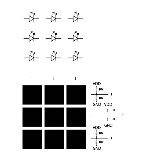
Design for next week's board
Failure 1: Board for a light sensor
I had already made an SMD-21 based board to read an IR-light sensor.
This week, I was planning to build the light sensor as its own breakout board, instead of relying on the Adafruit one. I purchased the light sensor on the board (the SI1145 was discontinued, so I purchased an Si1147 and 51), but the component was too small to create a board with the 1/16 bit on the mill.
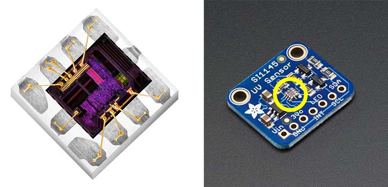
SI1145 Light sensor size
The footprint for the light sensor was too small for even the the 10 mil bit in the SRM-20, but I knew it would be able to fit. I right-clicked and opened up the footprint and used Change -> Smd to change the size of the pads to make them work with the machine.
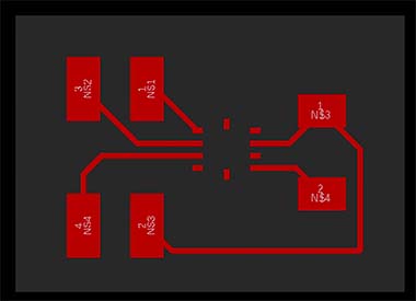
Breakout board with a new, larger footprint.
That worked well, but when I went to actually mill the smaller bit broke :(
I knew there was a machine that could cut PCBs with lasers in another lab. I prepared the files and went over, but the machine wouldn't actually "light" the design. When someone who knows how to use the machine is in the lab, I'm going to get help, but it's possible the software isn't working right now (I kept getting a message that it was in demo mode, which could be why it wouldn't actually communicate with the machine). I'm currently planning on just ordering the PCB from a manufacturer...
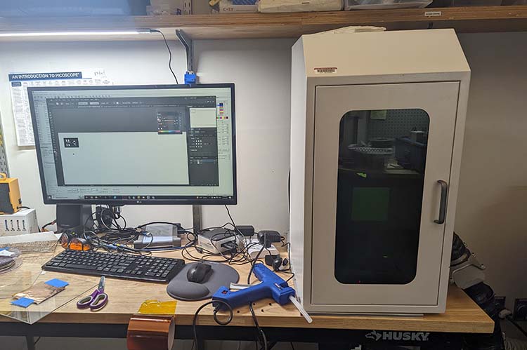
Very cool laser machine that I couldn't get to actually cut my design ;__;
Failure 2: Making a Grid with the built-in Capacitive Touch Pins on the SMD21E18
After researching for the class, I decided to make a multi-touch capactive touch grid. Reading through the SMD21 Data Sheet, I read something in Section 34: Peripheral Touch Controller, that made me think this could be done "out of the box." Spoilers: it was not that simple.
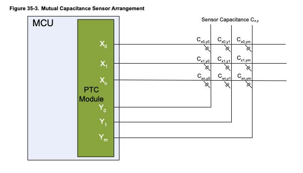
Interesting...
I tested the Adafruit Freetouch Library that's said to work with these pins. I connected a wire to one and it seemed to just work. I wasn't sure how that would translate into and X-Y grid, but I thought the next move would be to put a board together and try it.
With that tested, I went to go build the board. One of the things I learned this week was how to make a new footprint in Fusion, which I used to make the grid on my PCB design. To create a Footprint: Click File (in Fusion, not the Mac-level file) -> New Library. From there, you can select New Footprint on the top menu.
I went to mill the board double-sided which was its own adventure. I was eventually able to do it by flipping one side of the board vertically and taping the board down when I put it back into the machine. It had to be perfectly symmetrical to work.
Okay, the board was milled. I went into the CBA Lab to install the rivets. There, I ran into Quentin who told me that he was working with the Freetouch library, and it actually wasn't able to read the X-touch pins. In fact, all the X-pin related code is actually commented out in the library, as though someone had given up halfway. Oh no!
We make a test grid out of copper tape to see if we can get it working. As expected, the Y-pin worked with the Freetouch library, but any X-pins were ignored.
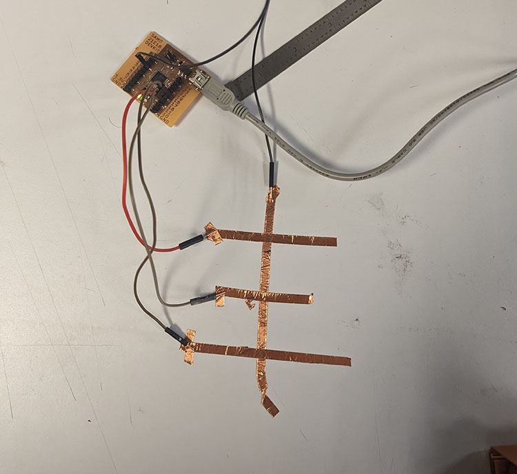
Test grid
We opened up Atmel Studio to try and program the board with their interface. This had a lot of intersting options (sliders, button grids), but ultimately the code that we downloaded didn't work as expected. Now that I know that Atmel Studio has a web interface, I'll take the time to program capabilities on my computer and move them over to a Windows machine to actually test the code on my boards.
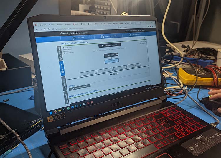
Atmel Studio web programmer
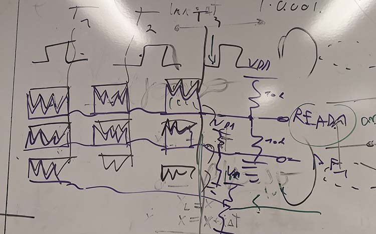
When that didn't work, I realized when I looked through the chip documentation again that there weren't even enough Y pins to build the tic-tac-toe board I wanted. That's when I pivoted to the step model with transmitter and reader pins described at the top.
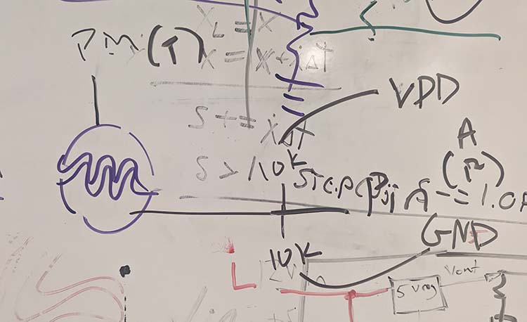
Simpler capacitive touch sensor
3x3 Grid