ORILUM
Touch Sensitive Light Talker
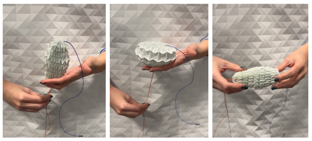
ORILUM is a 3D communication device featuring a kinetic origami interface, which responds to tactile input through motion and illuminated points of light.
The device has a capacitive thread-stitched surface,
embedded LED light wires, and a motor-activated linear motion mechanism,
allowing its membrane to contract and expand. ORILUM aims to bridge the gap between physical and digital communication, by providing a tangible,
playful medium for long-distance, non-verbal gestural interaction.
ORILUM can create a sense of presence with the communication partner from a distance, offering new avenues of expression and communication that are more engaging and playful.

The project components are: (1) An Origami Membrane; (2) Capacitive Touch Sensing for Input; (3) A Motion Enable Mechanism and Lighting for Output; (4) Connecting Pieces to secure the origami to the mechanism; (5) A Base to house the origami structure and printed circuit boards (PCBs); (6) PCBs; and (7) Arduino Code.
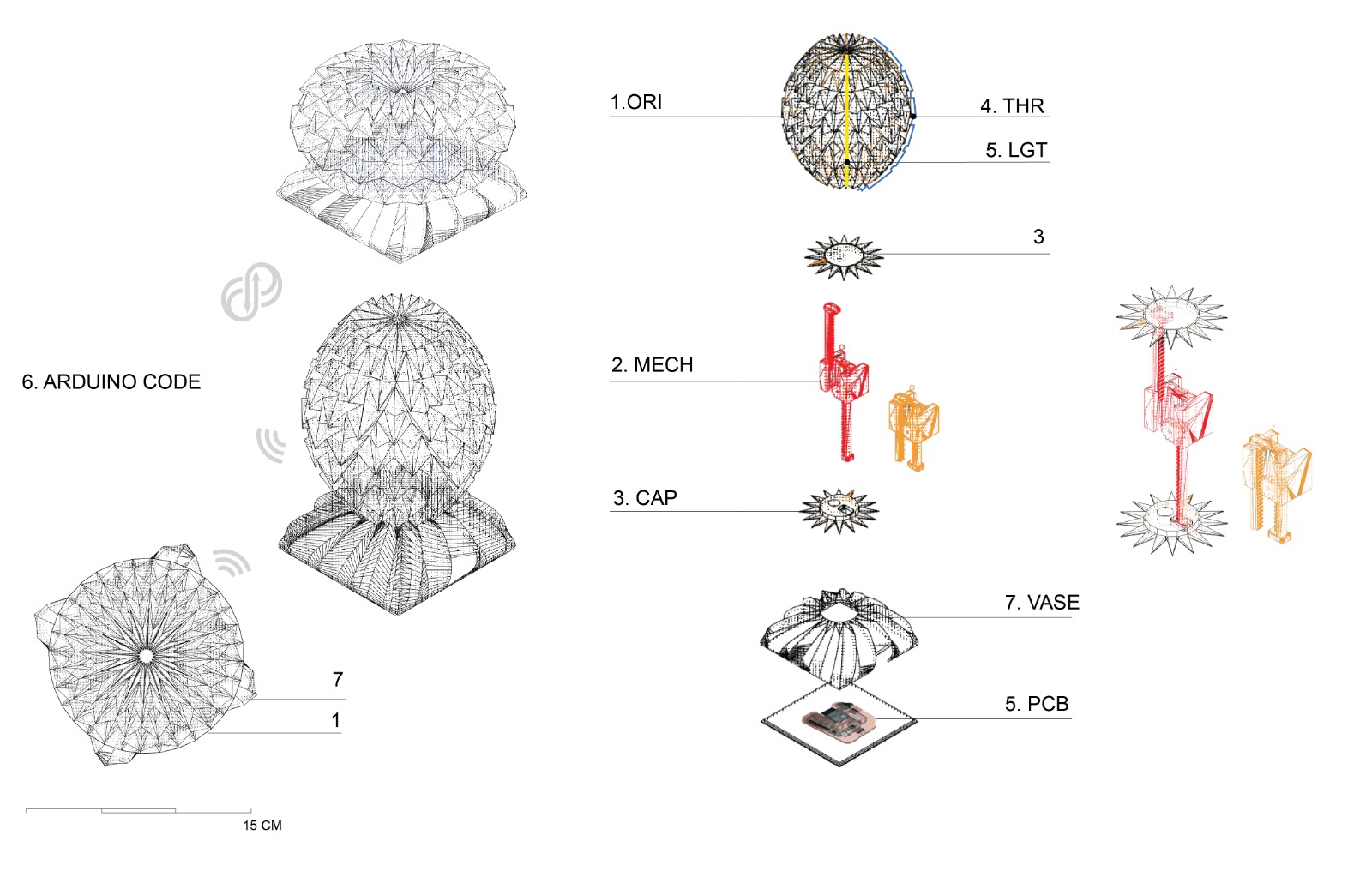
1. Origami membrane
I am using a generalized Waterbomb origami structure as a cinematic interface due to its developable 3D structure.
Origami presents an ability to form three-dimensional shapes by folding (thin) sheets of paper without introducing cuts or distortions. The regular base of a Waterbomb has mirror symmetry, and the sum of the sector angles around each interior vertex is 360º.
In particular, the Waterbomb origami has the ability to have a three-dimensional and symmetric range of motion while avoiding collapses or wrinkles.
A kinematic analysis of the structure is performed using a degree of freedom of movement under symmetrical folding to approximate a 3D model from a 2D folding pattern.
The model is developed as follows;
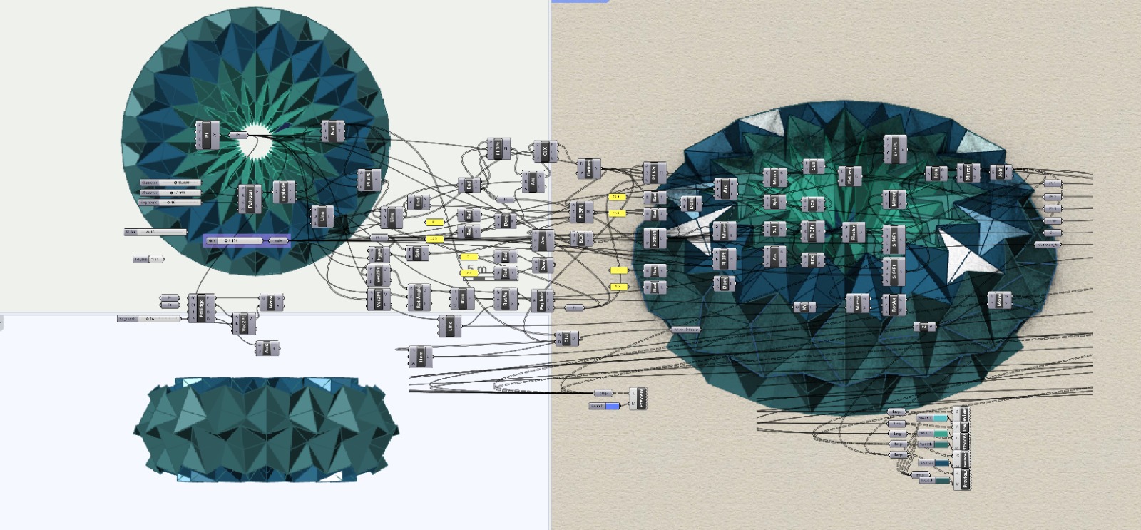
Firstly, a base mesh is generated by placing the fold of the tile pattern with parametrically defined valleys and mountains. Quads are used to tile a given surface by isometrically sampling the u and v coordinates within a certain domain.
Secondly, A numerical optimization algorithm is then applied to the base mesh to produce a deployable surface, constrained by the requirement that the total angle around a deployable vertex is 360 degrees.
The surface is swept on two target ones, a cylinder and a torus, which enables the distance between the waterbomb bases to be the largest and the shortest, respectively. The connection between the Origami left and right parts of the crease pattern is facilitated by six adjacent facets in the 3D model.
The fabrication of a waterbomb tessellation necessitates a multi-fold synchronous actuation. To simplify the process,
pre-folding crease lines were attained using a Zünd Cutter in the Center for Bits and Atoms (CBA) at the Massachusetts Institute of Technology at (MIT) Media Lab.
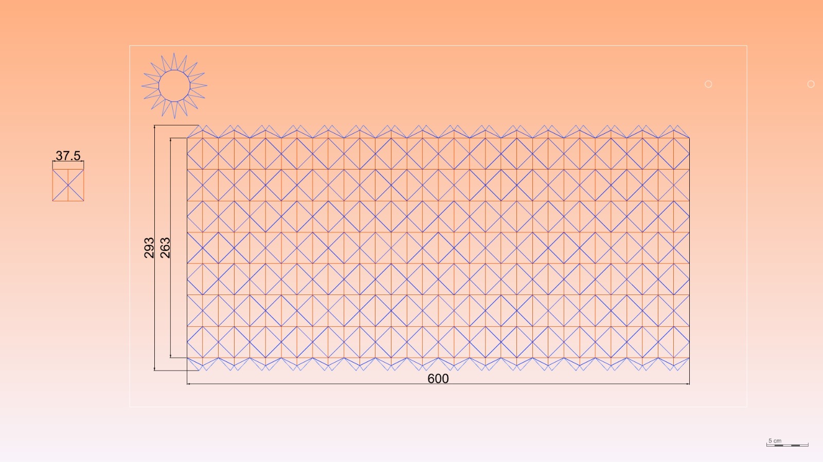
A model prototype was developed using Grasshopper and Rhinoceros to implement this method. Shown below is a rendered 3D model developed into a torus, with a crease pattern visualised with mountains in blue and valleys in orange, the folding process, and the first resulted origami piece.
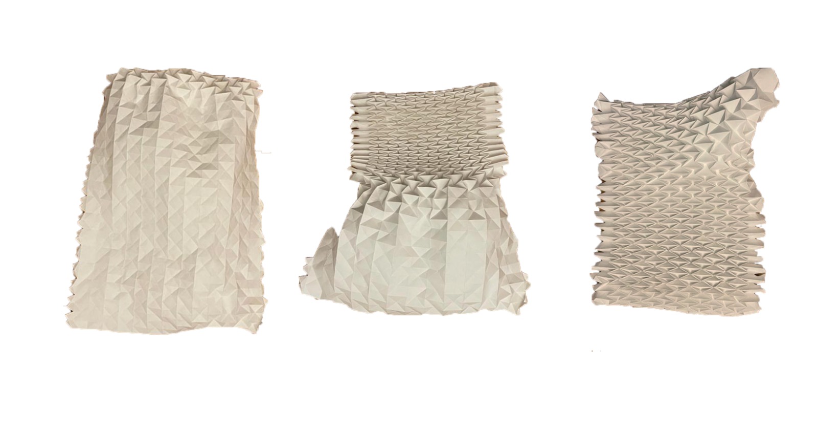
Initially, I attempted to use a 200gsm polymer, but it proved challenging. An effective alternative for fabricating this waterbomb origami would be to print the crease patterns on a textile using polymers, since textiles can be repeatedly folded without obvious fatigue.
I conducted a trial on the pleating machine from Tangible Media, however, the combined thickness of the pleated material and textile exceeded the permissible maximum. I finally selected 180gsm beige paper as the material of choice due to its superior foldability and durability compared to plastic sheets and traditional origami paper.
This being the first prototype, I am simultaneously evaluating various folding patterns, material choices and mechanisms to actuate the membrane.
I initially planned to actuate the membrane with wires for both motion and sensing,
leaving the interior free of any obstructions. I discussed the project with Jack Forman and Lyou Yeung,
to gain insight into their fiber robots and the possibilities of deploying them for this structure,
as an interesting option to be quieter and lighter than motorized components.
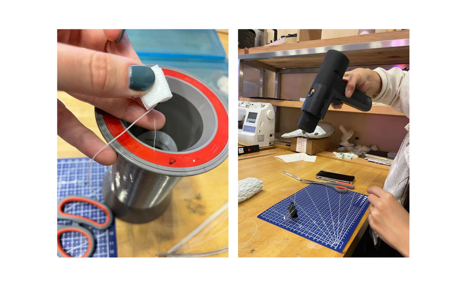
In order to achieve the desired range of motion within my time constraints,
I have chosen to use a servo motor to actuate the Origami.
As for the folding pattern, I tested some with two extra rows in the middle of the pattern to better accommodate an internal structure and tweaked
the geometry of the top and bottom layers in order to find the best way to support either a base or threads to actuate the origami.
The optimal layout for a natural movement ended up being seven rows and sixteen columns of 37.5 mm unit geometry.
2. Capacitive Touch Sensing as Input
The touch sensing is embedded copper wire capacitive sensors encapsulated within the 3-D deployed structure.
The accuracy of touch sensing was tested using three distinct capacitive sensors:
a 320 μm width wire sensor, electric paint from Bare Conductive, and 316L stainless steel thread.
Results revealed that the small area wire sensor was better suited for machine-aided sewing, while the Adafruit-sourced,
thin conductive yarn was more suitable for manual hand sewing. In contrast, the electric paint did not provide satisfactory sensitivity.
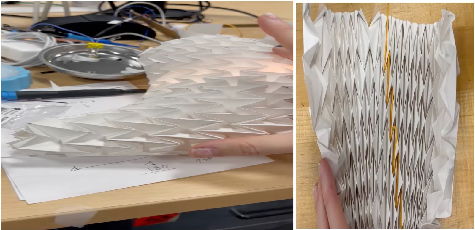
The Origami achieves capacitive sensing by sewing conductive wire into a staggered pattern within the folds of ORILUM origami pattern.
The wire is sewn into the folds of the pattern in a staggered fashion, allowing for a more natural movement when stroking the Origami.
This stitching methodology was adopted to create a more natural touch experience, wherein the movement of a hand caressing the origami corresponds
to the lighting of light points in the same areas.
Initially, the wire was placed only at the vertices and edges of the folds, and then along the edges to increase the overall capacitive surface area.
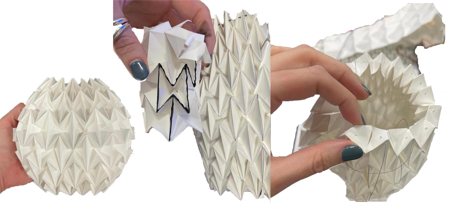
I evaluated the range of data of the capacitive sensor in conjunction with different microprocessors to assess their ability to detect finger proximity without physical contact.
The data returned by the wires connected to the ESP-32-WROOM microcontroller
Touch pins were able to detect variations induced when touching the wire connected to the GPIOs with a finger,
making it suitable for my design due to its required capacitive capabilities.
3. Motion Enabled Mechanism
For the design of the movement mechanism for the Origami prototype, I considered four possibilities.
The first option was to attach the mechanism to a wall with one end of the Origami fixed, and the other end moving.
The second option was to place the Origami in the center of a frame and embed the drive mechanism with wires tied to a coil attached to a motor.
The third option used a platform with a linear movement structure in the middle of the Origami. The fourth option was to have a worm-type mechanism inside the Origami,
connecting it to an external PCB. All options were considered to achieve a symmetrical movement similar to that of an animal belly when breathing.
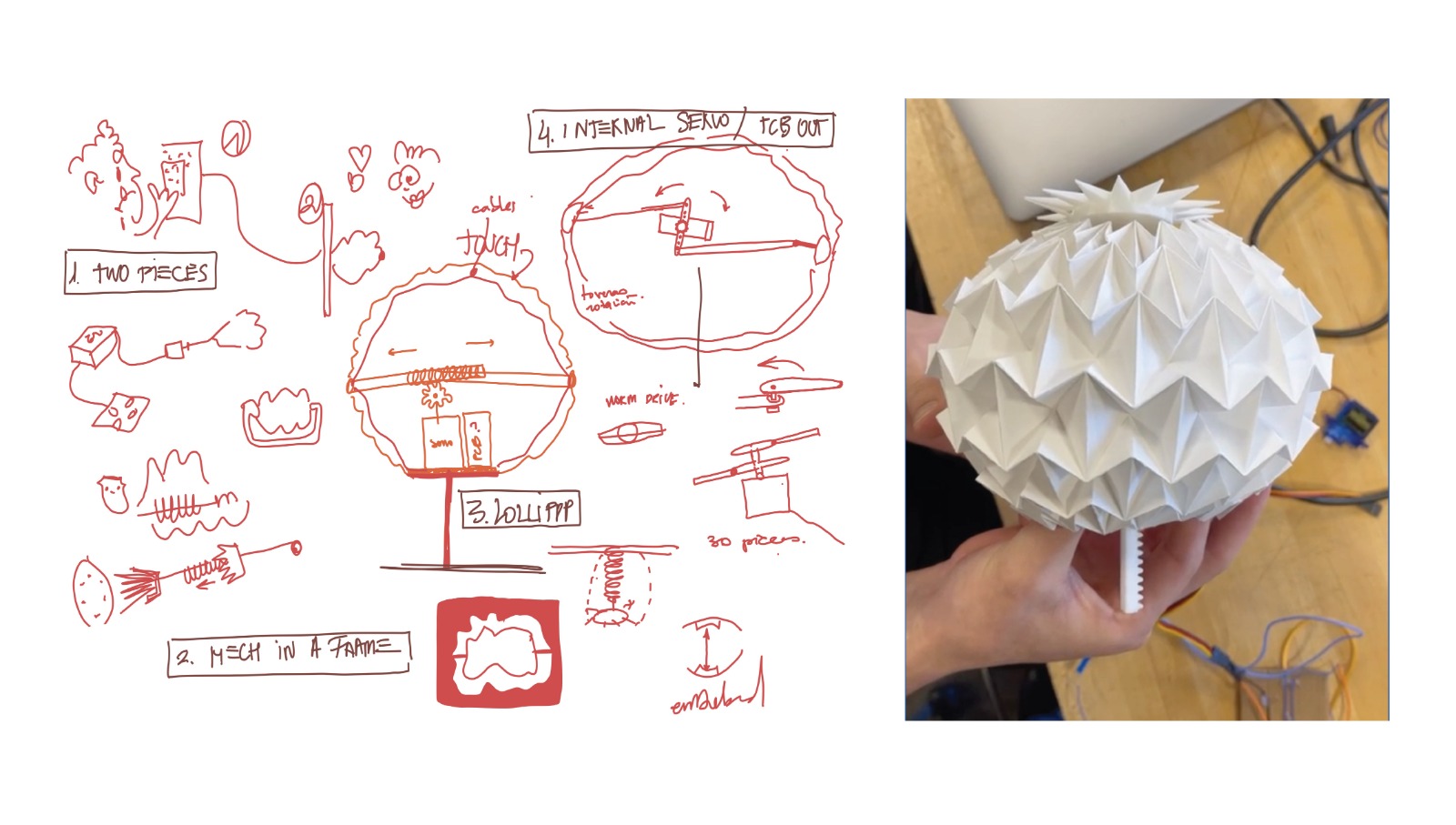
The elongation will be too much, so you would have to clamp the device to a deep base, which would detract from the natural movement of ORILUM within the constraints of this origami geometry.
I will then reduce the mechanism to its smallest size and place it next to the motor inside the origami. This will leave the option of hosting the PCB inside or outside of ORILUM.
I opted for a combination of the last two options. The motion of origami is driven by a motor connected to a rack and pinion system, which converts rotational motion into linear motion. The pinion is equipped with two racks, one on each side, which are affixed to the two endpoints of the 3D Waterbomb.
The two racks interact to create an expanding and contracting motion, enabling an elongation or shortening of the origami's shape.
The process comprises several steps, including establishing the position of the servo motor and pinion gear, determining the direction of the pinion rotation, and configuring the rack and pinion to interlock.
3.1. Set a Servo Motor to a Pinion Gear.
Initially, various motors were evaluated to identify the smallest unit capable of providing sufficient power to move the 3D Origami. At first, I used a HV digital torque HItec hs 7245 mh.
The Mini 360 Degree Continuous Rotation Servo FS90R was ultimately selected for the task due to its miniature size, 9g weight, and capacity to provide the full range of motion needed.
It was designed a pinion gear replacement for the Servo, allowing it to operate with two racks.
3.2. Interlock the Racks and the Pinion
The motor is housed within a structure, connected to a gear, and two racks are situated in parallel that move in opposing directions.
From the motor's rotation from 0-360 degrees, the racks reach the furthest point from each other and thus open the origami.
Upon the return of the motor to zero degrees, the racks follow the same movement and return to their initial positions, thereby closing the origami.
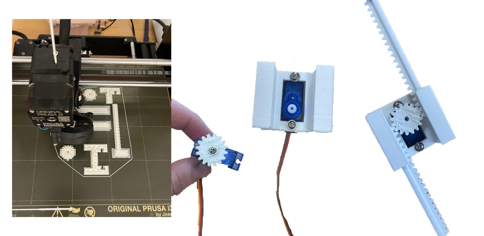
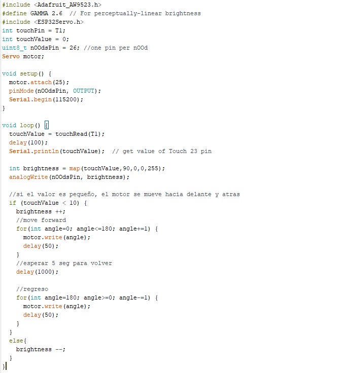
Next, I am preliminarily testing Neil's design of the ESP32 with an LED connected to a PWM pin, a capacitance sensing pin, and a pinion and rack attached to a servo motor connected to another PWM. This is the first time I'm testing these components together.
4. Connecting Pieces to hold the Racks to the Origami
The connecting pieces designed are polygons with 16 sides, which correspond to the number of columns in the origami crease pattern.
The base of each side is comprised of an isosceles triangle, with a height equal to the side length of the origami unit in the first and last rows of the 2D crease pattern.
These triangular tabs in the crease pattern are then aligned to create a pyramid shape matching the base piece.
The base connecting pieces is printed on flexible material to allow for bending and is embedded beneath the triangular origami tabs in order to prevent displacement due to the motor force used for movement.
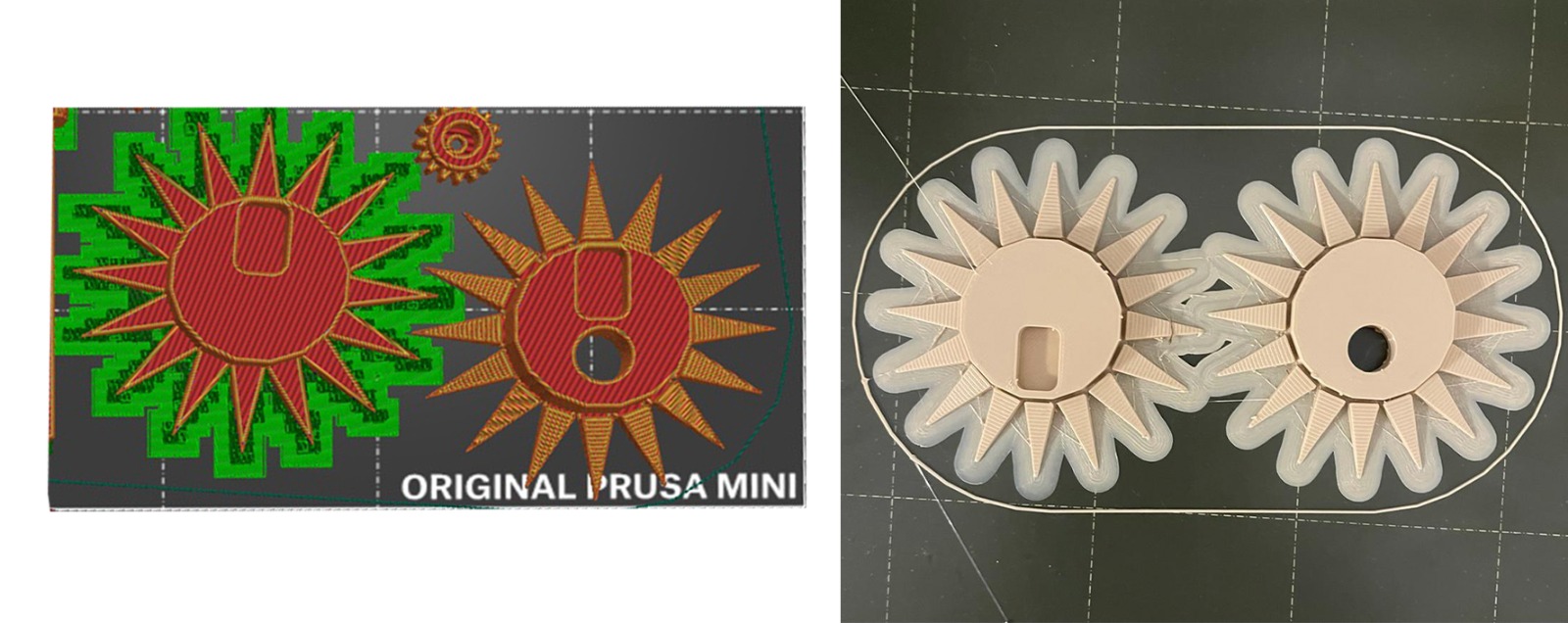
The 16-sided polygon is unified with its triangles. These triangles are meant to be bent.
I initially attempted to design and print a piece where the junction between the polygon and the triangles was equal to the Prusa's minimum printing thickness (0.05 mm - 0.07 mm).
After numerous trials, and the piece breaking apart after about twenty bends, I opted to utilize a flexible material for the final product. I decided on PLA Flexfill 98A in peach color.
When printing the bases with flexible PLA, I was unable to remove the excess material afterward, so I had to reprint them without adding any supports or bases to the bed.
To achieve this, I simply increased the temperature of the bed of the Prusa MK3 printer to 70 degrees.
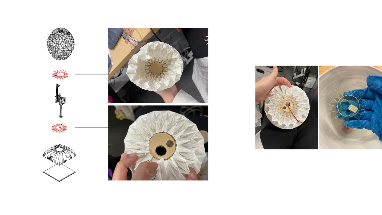
Halfway up the piece, there are holes to house the zippers of the mechanical racks, while through-holes are present to allow the passage of motor leads and other components (e.g. lights). There is a gap between the top and bottom holes in each of the two pieces, when seen in top view, with a distance equal to the width of the piece that holds the servo motor.
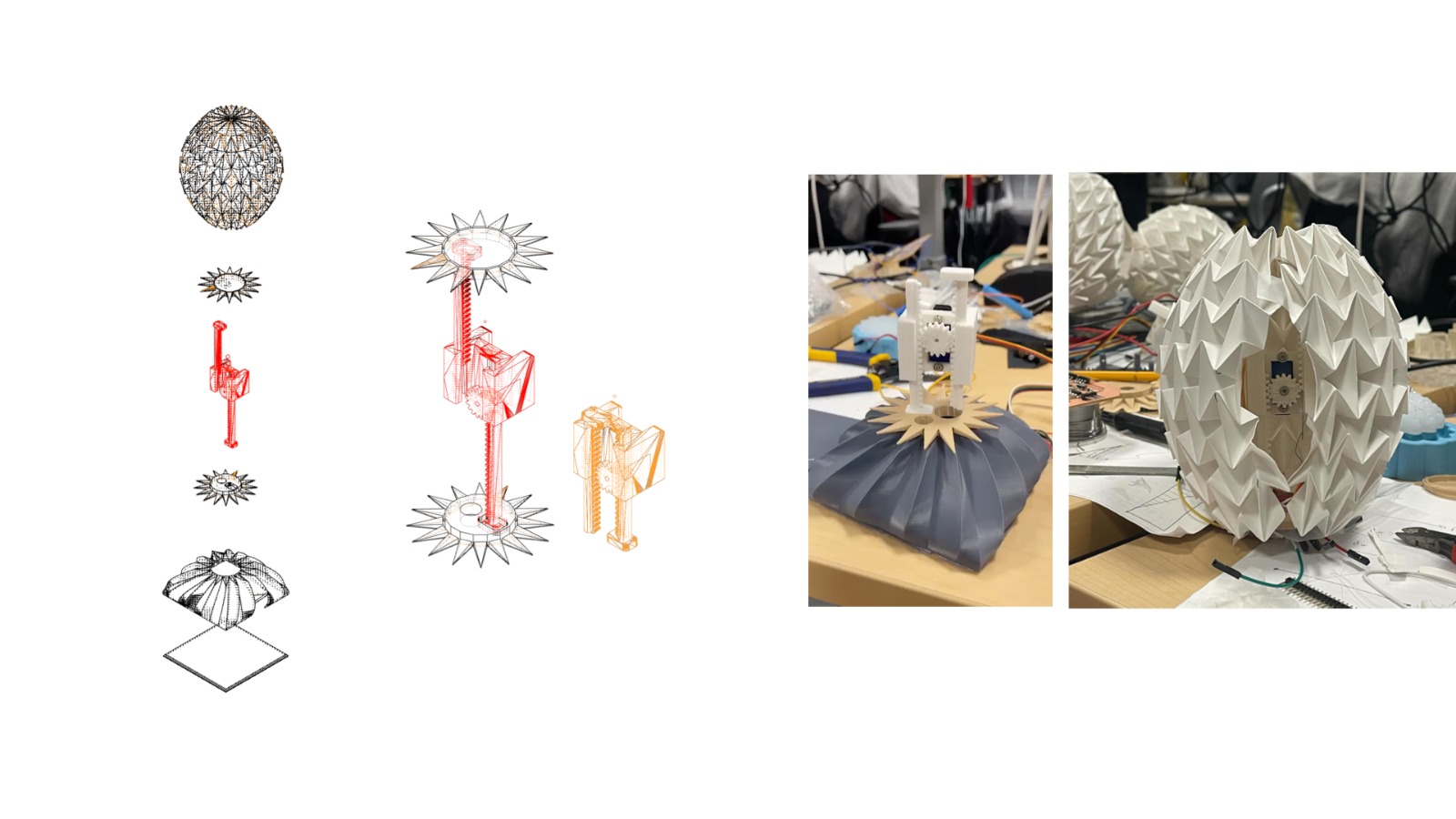
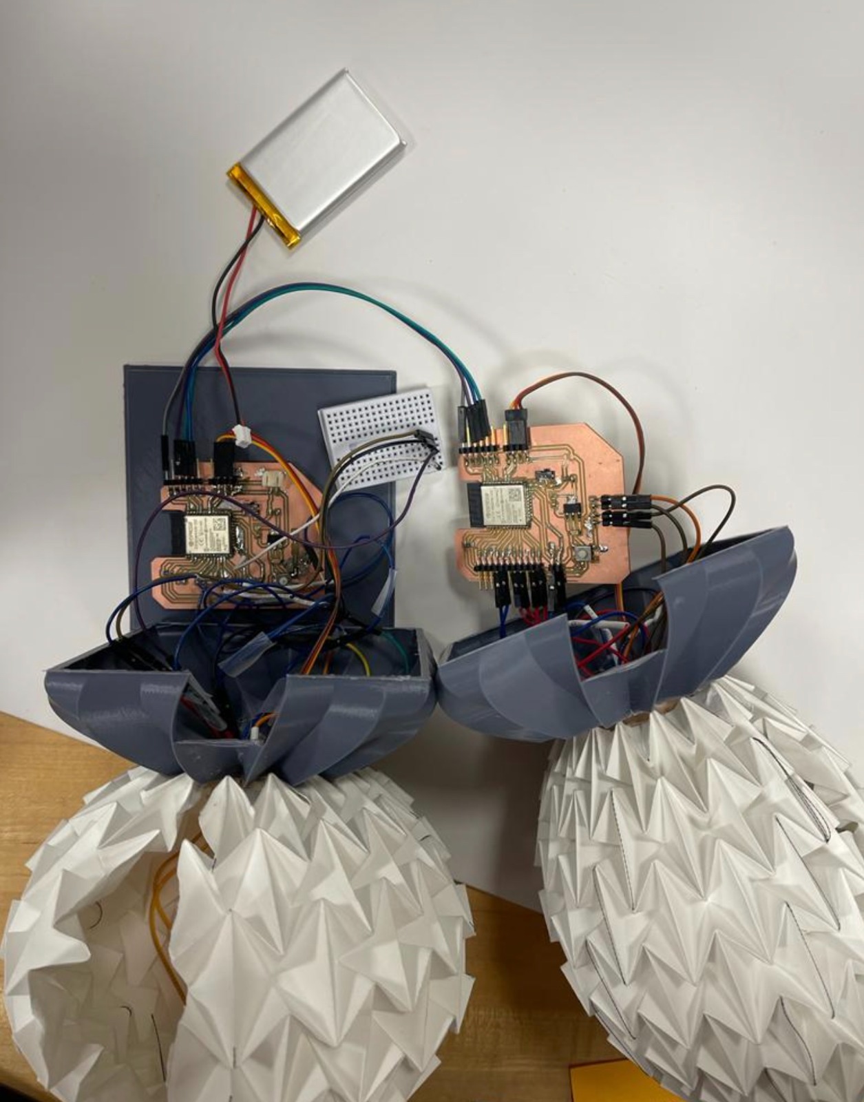
The three systems are integrated in an intricate manner, the threads are woven within the origami pattern, the LED lights run along the inner membrane, blending into the design. The conductive wires and LED filaments will be connected to the pins of the microprocessor at the bottom of the Origami, before passing through a hole within one of the sixteen-sided polygons and entering the enclosure that contains the Printed Circuit Board (PCB).
5. PCB design
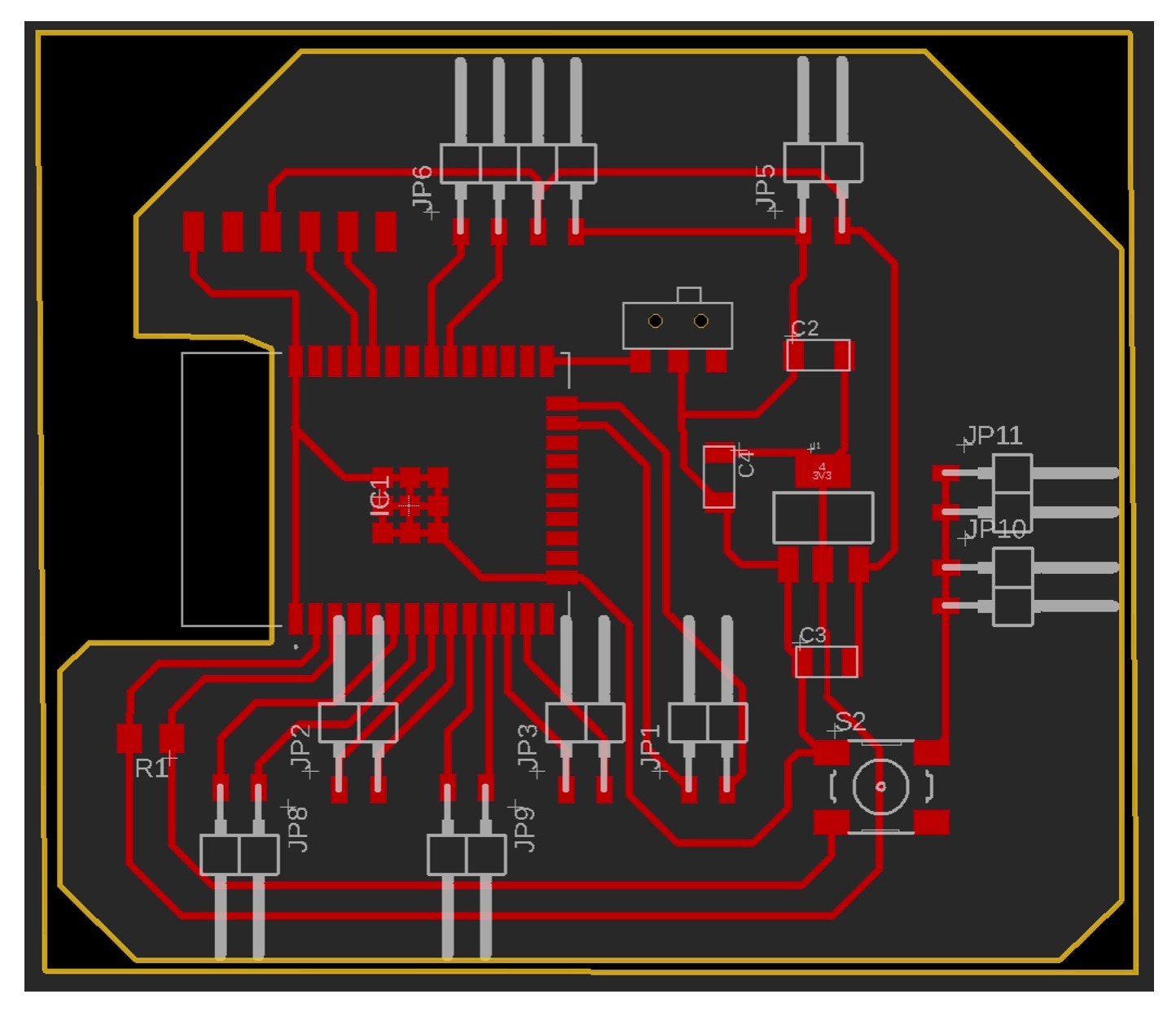
The ESP32-WROOM microcontroller was selected for its WiFi connectivity and integrated capacitive sensing capabilities.
Six Pulse Width Modulation (PWM) channels are assigned to control the brightness of each of the six nOOd light filaments. A seventh channel is assigned to control the servo motor. A digital-to-analog converter is used to adjust the light intensity based on the value of the touch input.
Additionally, six capacitive pins are used to connect the capacitive yarn threads. To power the system wirelessly, a battery is included in the circuit.
Bellow the schematics, where I used the following components:
ESP32-WROOM-32 D0WDQ6 32
SW_SLIDE-SWITCH for prog run component (from the fab library)
VR_REGULATOR_SOT-223 for IC1 3.3V
R1206 for the resistors
CAP_UNPOLARIZED for the capacitors
CONN_06_FTDI-SMD-HEADER (6 pins, FTDI header)
SW_SPDTSWITCH (3 pins, can use it as a FTDI header)
SW_SWITCH_TACTILE_6MM6MM_SWITCH for the button switch for reset
6. Arduino code
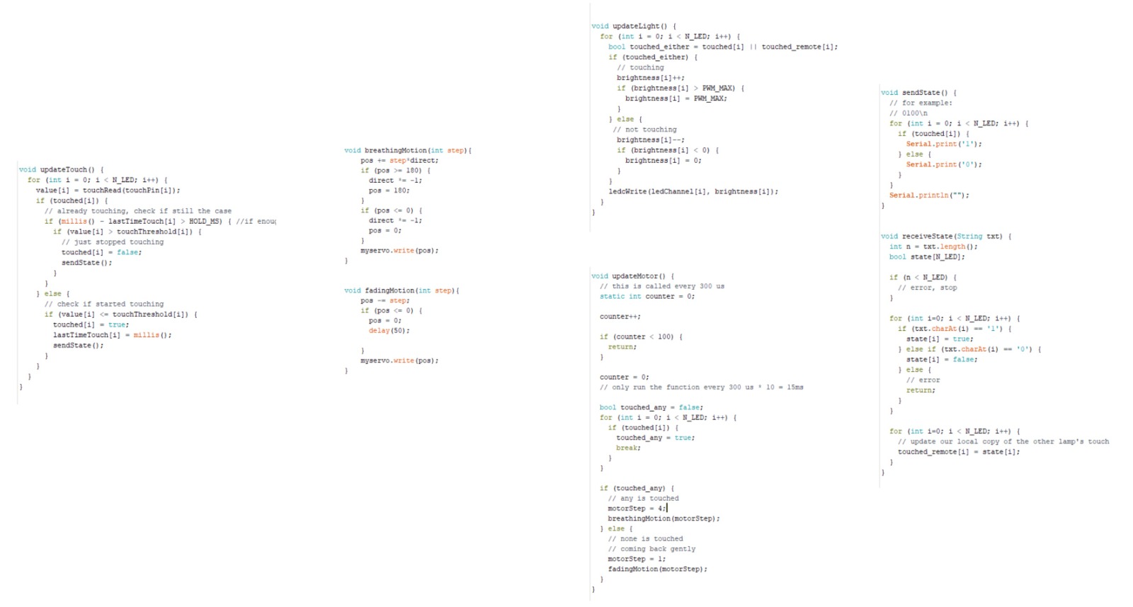
The code is organised as follow: the function updateTouch(), receives the values of each of the capacitive threads and, based on that,
enables the control of the brightness of the light and the movement of the motor through the functions updateLight() and updateMotor().
In order to dim the lights effectively, I followed the instructions found at https://www.electronicshub.org/esp32-pwm-tutorial/. Initially, I encountered an issue when connecting the light and the motor at the same time as they were incompatible. After realising that I had to put them through separate channels, the issue was resolved and the lights worked properly.
The first iterations of the code for the movement of the motor did not result in a very stable movement of the origami.
To address this issue, I added two other functions: "breathingMotion" and "fadingMotion".
The first activates the movement when any of the capacitive wires are touched, while the second determines the way in which the motor stops once the wires are no longer touching.
This ensures that the movement of the motor is more stable and consistent when the capacitive threads are touched.
The next iteration of the code allows the lights and motor movement to fade at the same time.
Together, these changes have effectively improved the control of ORILUM. At this stage, when you touch the origami structure,
the capacitive sensors woven into the design detect the contact and activate a servo motor, creating movement.
This movement is synchronized with the light filaments, which also turns on when you touch ORILUM membrane. When you let go, the light fades out and the movement of the servo motor stops synchronously.
Ultimately, I established a serial connection between the two Origamis, thus allowing them to send and receive data every time a change occurred.
To do this, I used the Arduino Serial.read()library.
(7/7) The vase
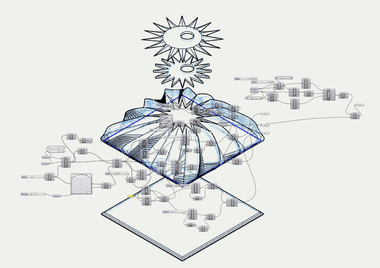
The vase only allows KORILU to expand and contract while housing the PCB. It has some grooves through which the Origami slides since the movement needs that degree of freedom.
The Grasshopper routine transforms the cap stellated polygon into a square, leaving the height intact in slots to accommodate the origami sliding.
Attached a couple of videos from demo day!
What materials and components were used? Where did they come from? How much did they cost?
(1) 180 gr. folding paper
(2) Flexible PLA (Flexifill 98A)
(3) White and Gray Amazon basics PLA, and two 180 degree servos
(4) PCB components described above. In addition, I used a Lithium ion polymer battery, 3.7 V, 2500mAh model (Adafruit Industries)
(5) Stainless Thin Conductive Thread - 2 ply - 23 meter/76 ft (Adafruit)
(6) 7 x nOOds - Flexible LED Filament - 3V 300mm long - Warm White (Adafruit) [ID:5503] = $31.50
What processes were used?
I used a combination of 2D and 3D design for the Origami and packaging pieces, as well as for the mechanism pieces.
To build the mechanism pieces, I employed additive fabrication processes such as 3D printing.
To create the Origami pieces,
I employed a Zund machine to mark valleys and mountains within the design and experimented with a laser cutter and a crase machine from TMG for the same purpose.
For the electronic design and production, I used Fusion 360 for the embedded microcontroller design and Roland for milling.
To interface and program, I used Arduino.
Who's done what beforehand?
Conceptually, the MIT Tangible Media Group (TMG) has worked on telepresence and physical forms of displaying emotions.
Along wiht other peers from TMG, we developed HairIO: An Unobtrusive Non-Verbal Communication Device,
where were examined the use of hair and fur-based interfaces which could offer a gentle but effective way of communicating.
Physically and materially, the Diffusion Choir project from soso limited utilizes many two-dimensional elements that transform in shape,
creating the of a flock of birds in flight when they're actuated at the same time.
I would like to thank to Alfonso Parra, Andrés Rico, Quentin Bolsee, Miana Smith and Dave Preiss for their guidance and help throughout the whole HTMAA course.