10 Networking and Communications
This week's assignment is design, build, and connect wired or wireless node(s) with network or bus addresses.
Circuit Design
I am using the ESP32 microcontroller, following this guideto understand the pinout diagram.
Following Neil's initial model of the ESP32 board (hello.ESP32-WROOM board)
I'm adding some FTDI headers to connect to other I/O devices.
Initially with a servo motor. I used this page to learn how to use Servo Motors with ESP32.
To start designing the schematic, I use the following components:
ESP32-WROOM-32 D0WDQ6 32
SW_SLIDE-SWITCH for prog run component (from the fab library)
VR_REGULATOR_SOT-223 for IC1 3.3V
R1206 for the resistors
CAP_UNPOLARIZED for the capacitors
CONN_06_FTDI-SMD-HEADER (6 pins, FTDI header)
SW_SPDTSWITCH (3 pins, can use it as a FTDI header)
SW_SWITCH_TACTILE_6MM6MM_SWITCH for the button switch for reset
Below are the schematics:
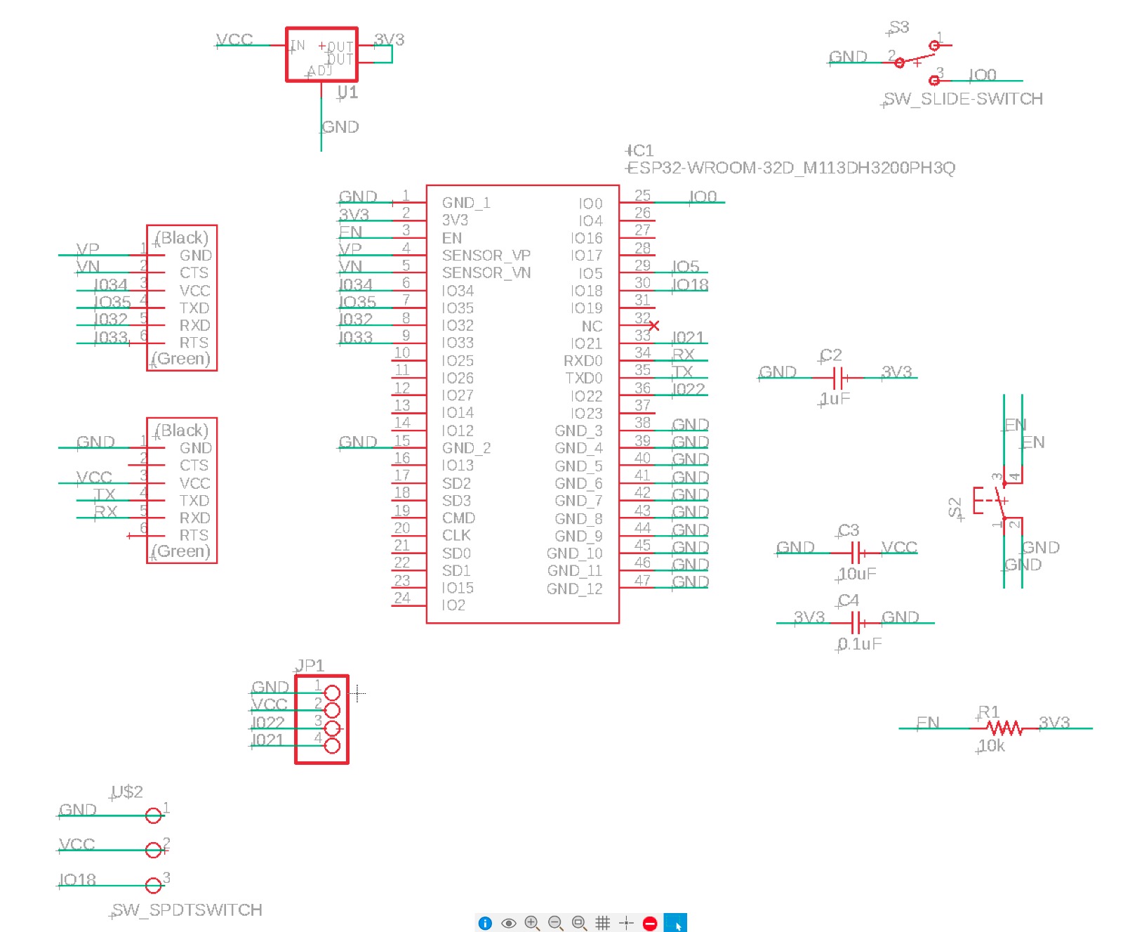
I am leaving this for the final project here.
For proof of concept, I am using Neil's ESP32 board example.
This time I milled my PCB on Andrés Rico's “Clank” milling machine using mods to create the machine's gcode.
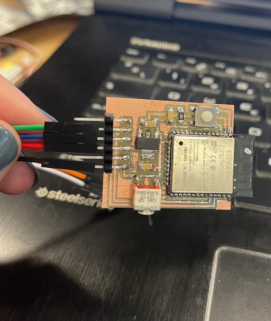
First of all, I am connecting the microcontroller to WiFi and getting a an IP address assigned my ESP32 board.
I am using the WiFi.h library, which will allow the connection to the network, I need the network name and password.
After uploading the code to my ESP32 board (remember moving the switch to upload), I opened the Arduino IDE serial monitor at the baud rate of 115200, reboot my ESP32 board.
Successfully connected to the WiFi network! and got an IP address assigned to it.
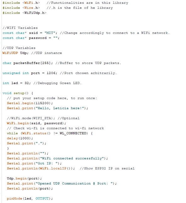
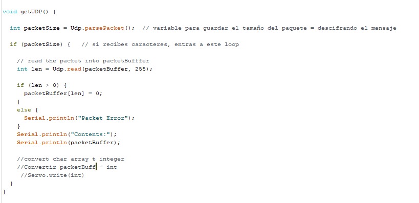

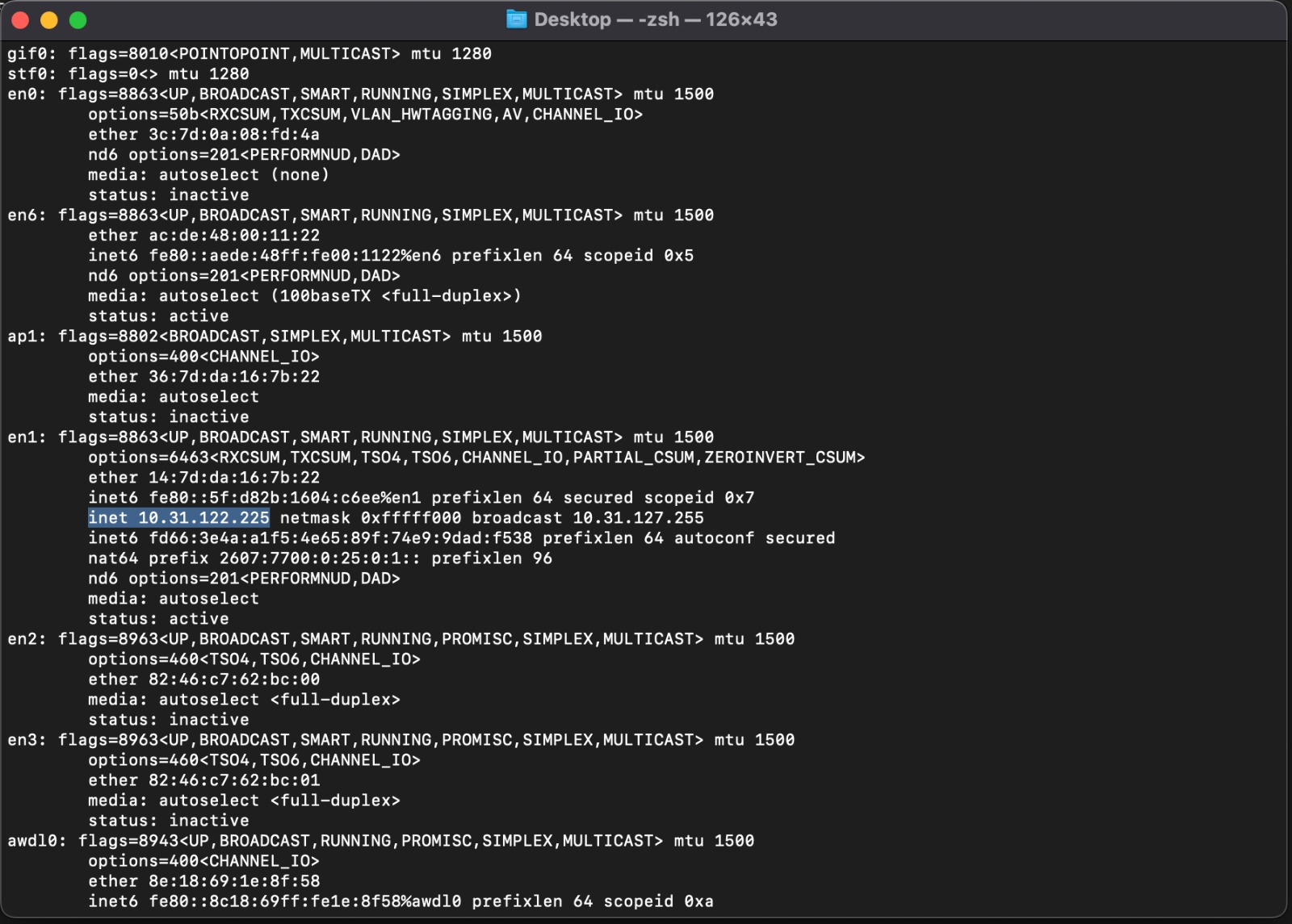
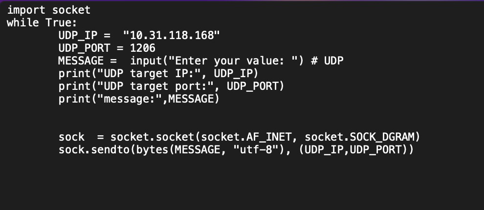
Secondly, I am using the UDP communication protocol to send a message to the previous IP, so establishing UDP communication between my Mac and Arduino on my PC. I find the IP address on my Mac, and make a program using Python’s socket module to communicate with my PC.
Lastly, I am connecting the ESP32 to my Mac -they're talking!
