02 Electronics Production
This week we fabricated a in-circuit programmer (PCB board). To do this, I milled the blank red cooper PCB, soldered on the components, and programmed the programmer.
Tools: PCB Milling Machine, Soldering Irons, Air Gun
1|3 Milling Machine
The thinniest traces than can be printed with an optimal result are .02 mm.
To prepare the board, I cut the cooper clad and glue it on the base of the machine and place the end millers on the tip with the help of the magnet.
I used 1/32 end mills for engraving and 1/64 end mills for cutting.
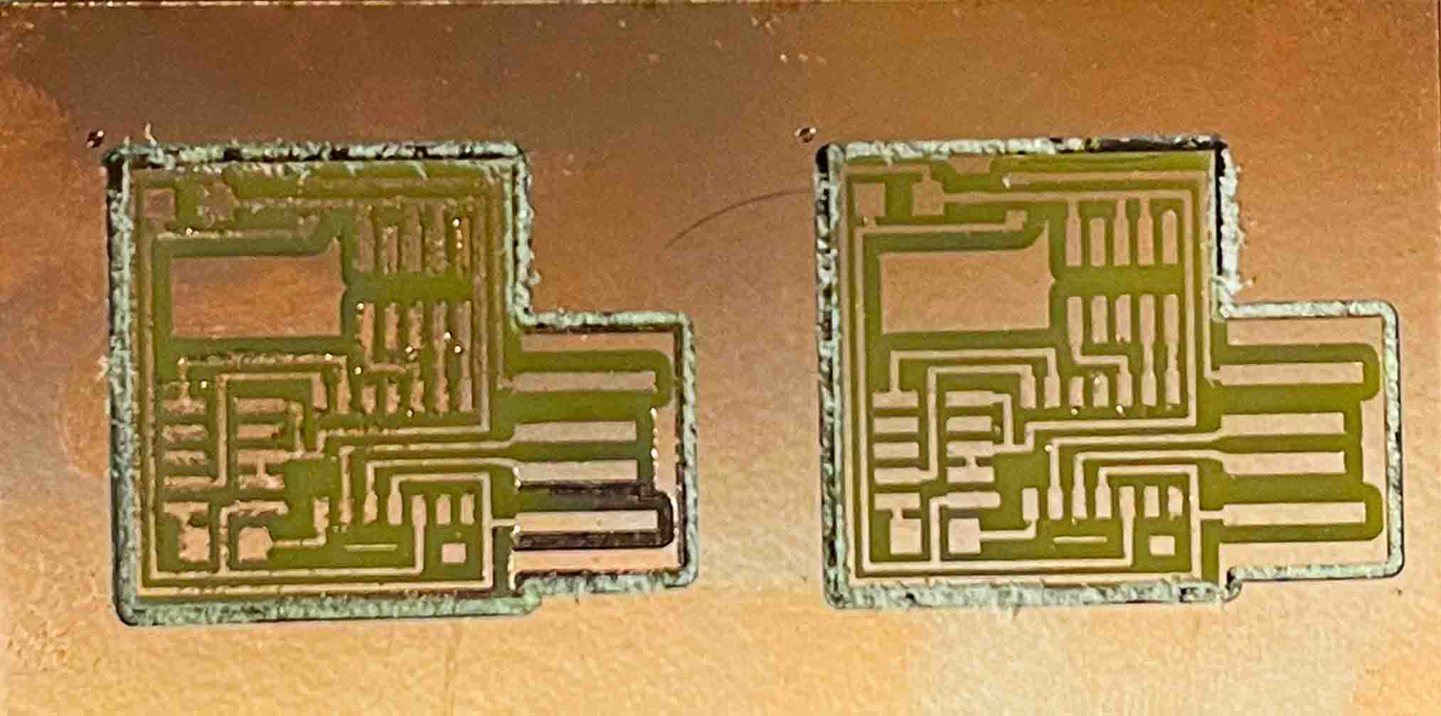
First time, my file rendered and cutted, but didn’t all the traces well. The milling speed was to high.
I lowered the speed of the machine and then obtained a good result.
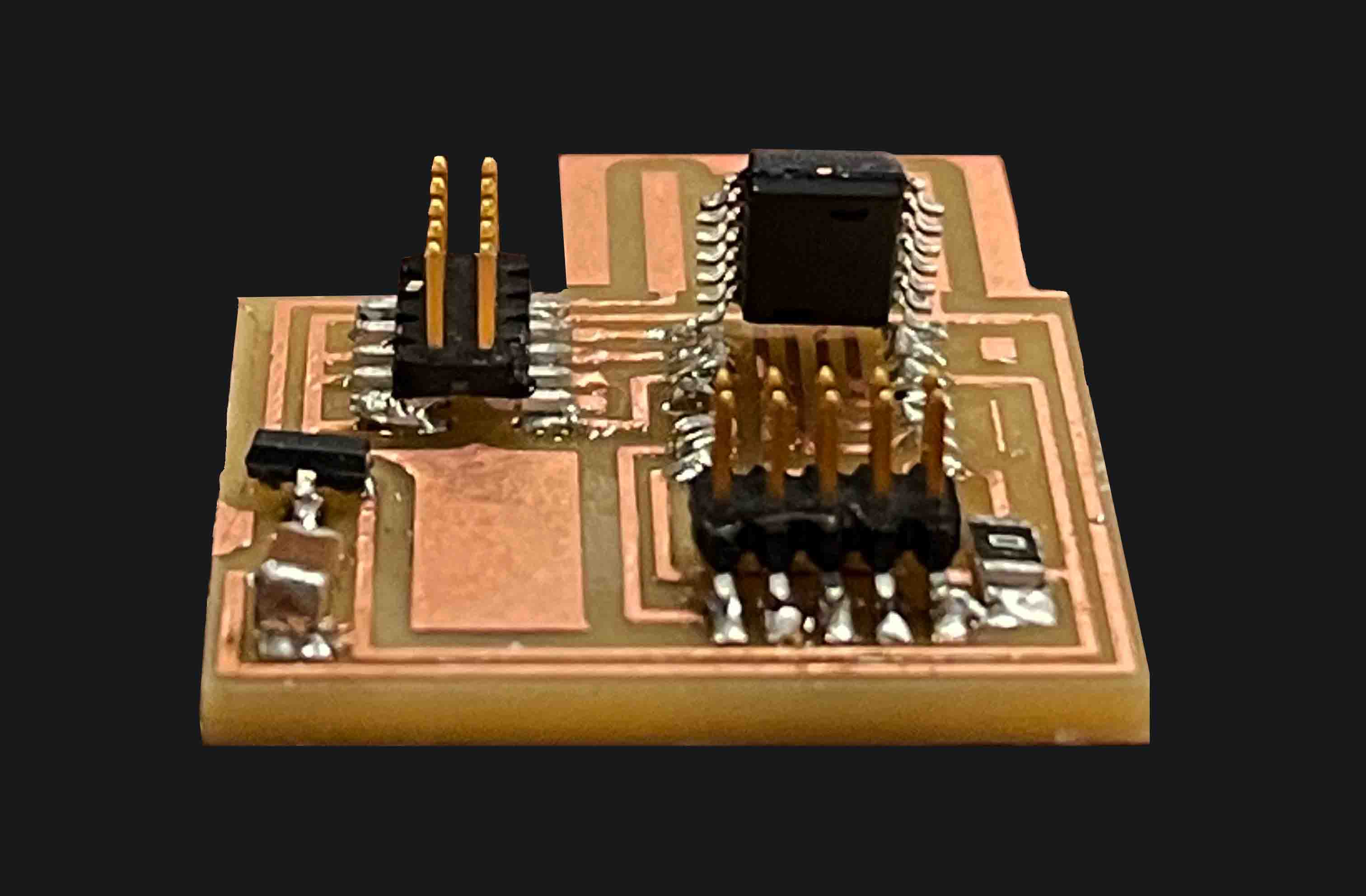
2|3 Soldering
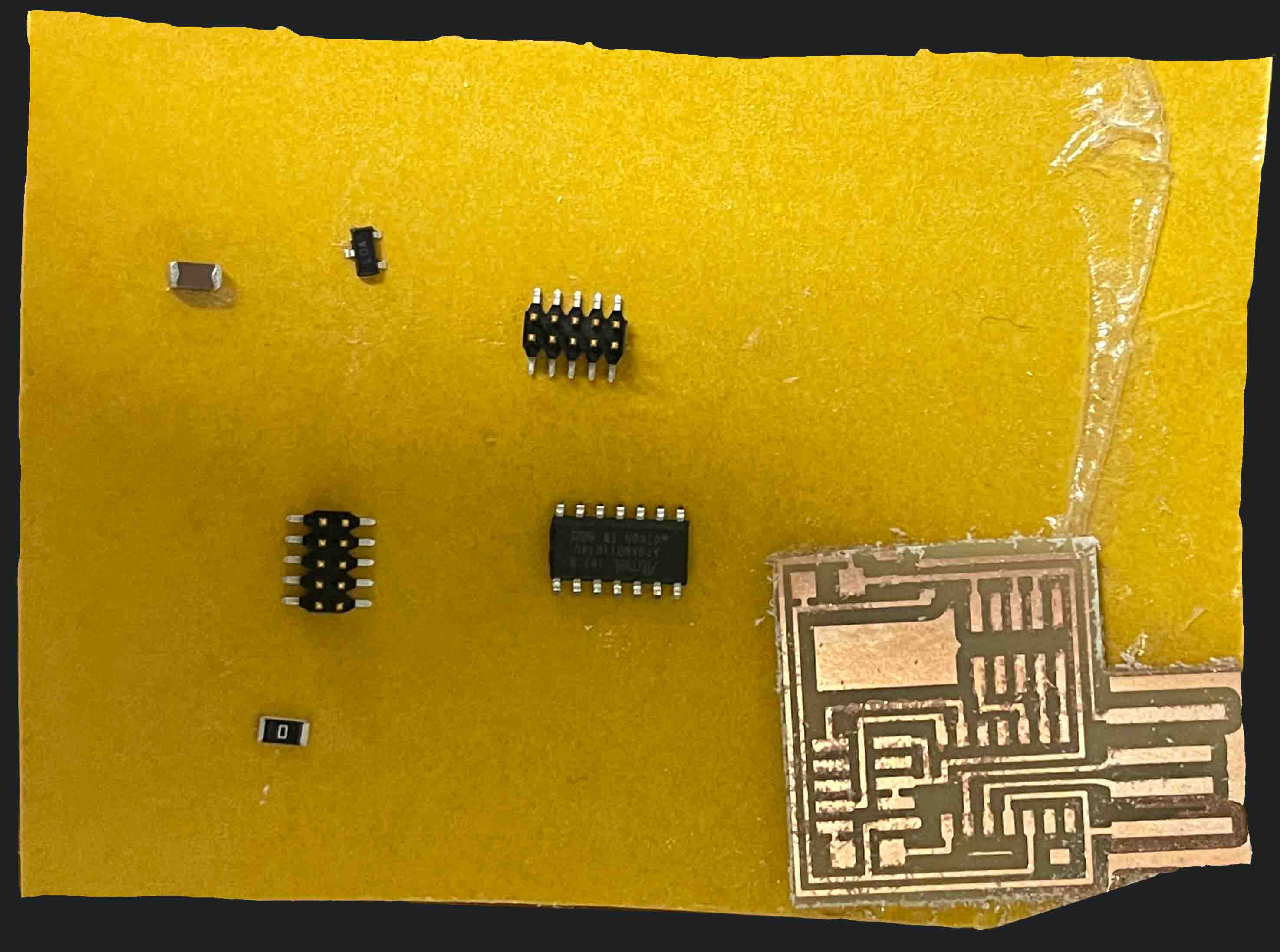
Once I had my black PCB, I collected and sorted the components needed to start soldering.
This was my first time welding. So, I did a few tests on the PCB that I had previously discarded.
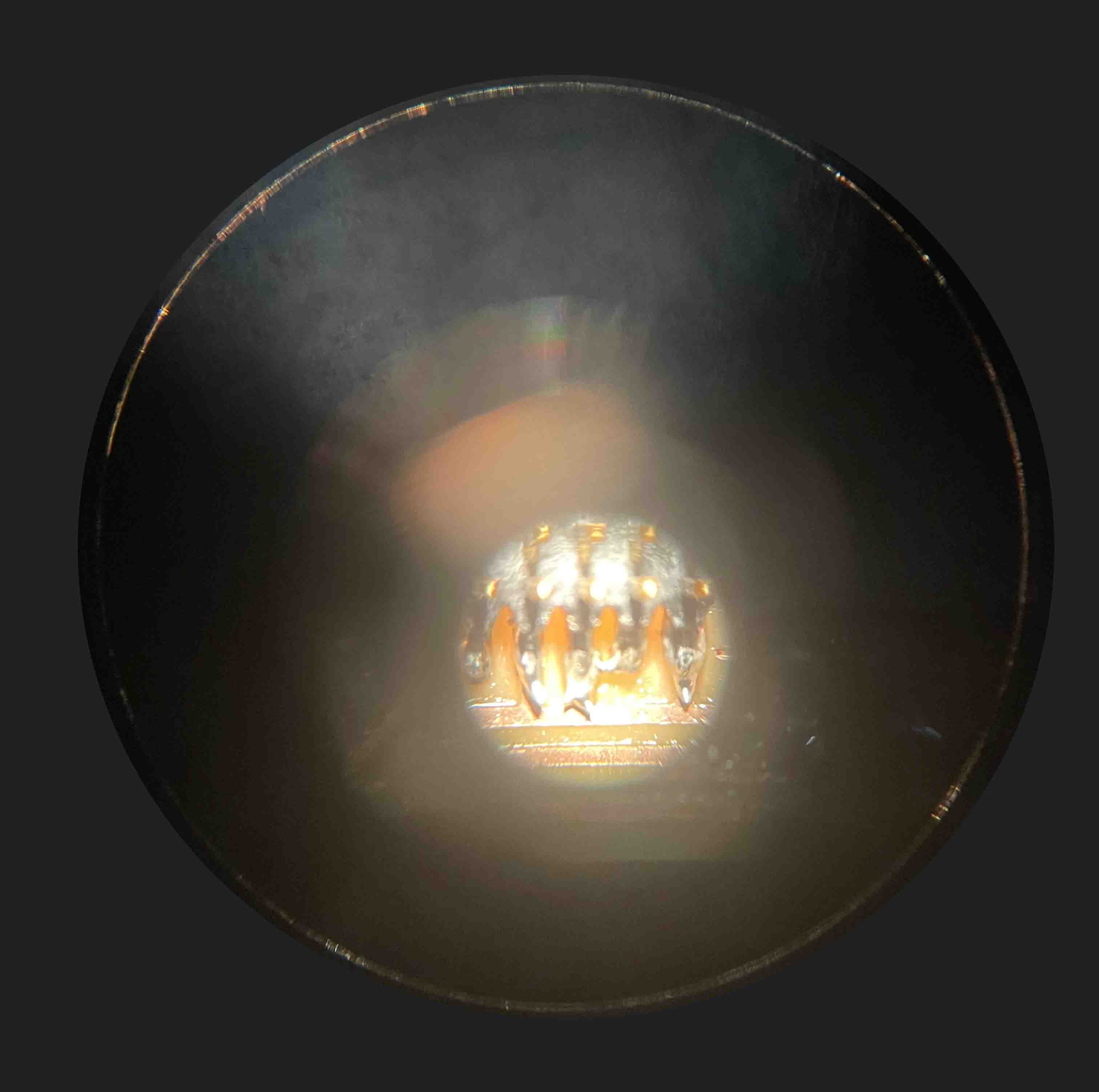
I helped myself with the microscope, at first it cost me, but then I was addicted to looking for faults!
When soldering the components, it was important to keep in mind that one of them (microprocessor) had to be placed in a specific position (with the white dot facing up).
Also, during the entire welding process I used the Flux liquid that made it much easier!
3|3 Programming
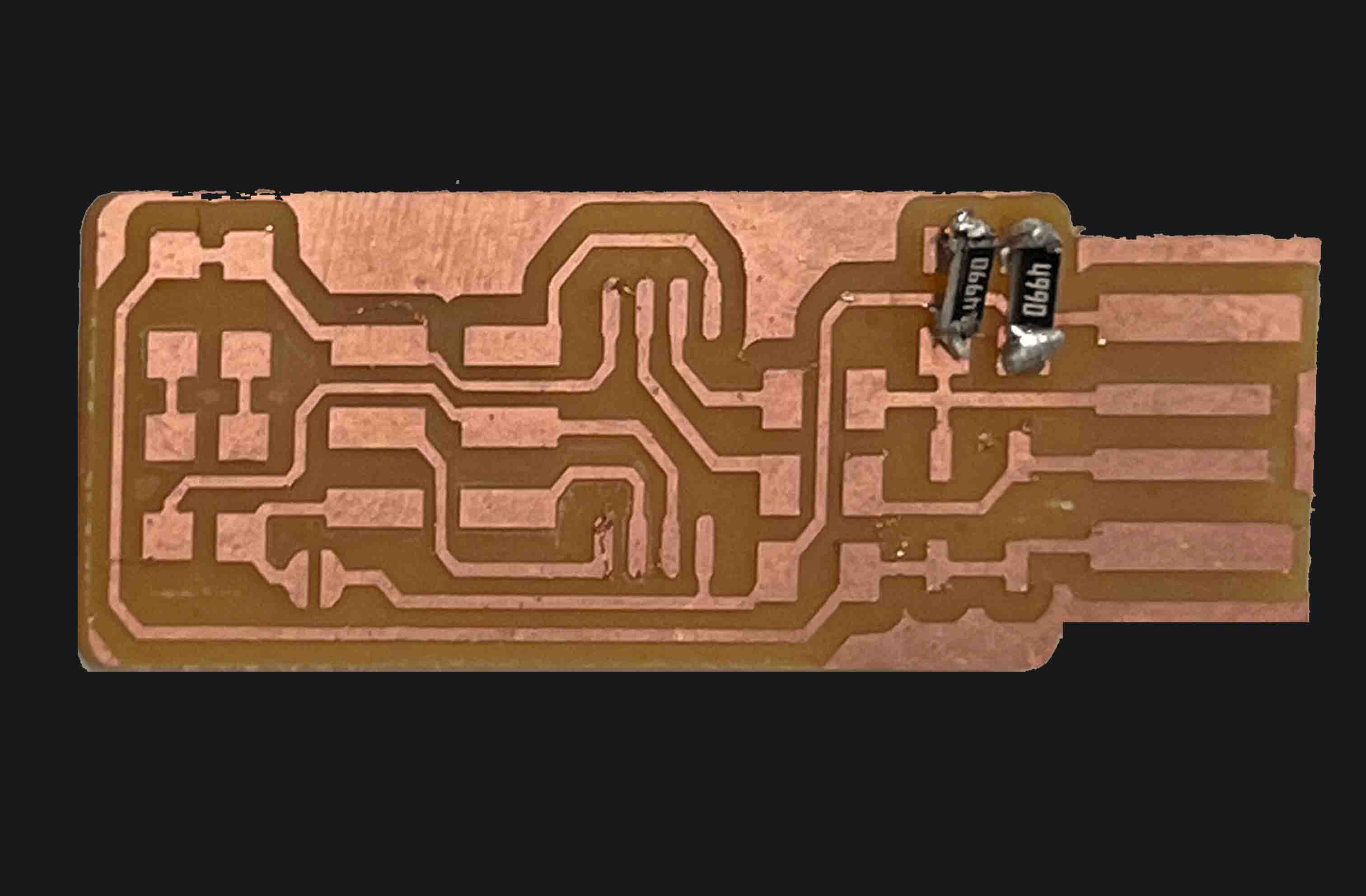
Once I had my board I was ready to program it.
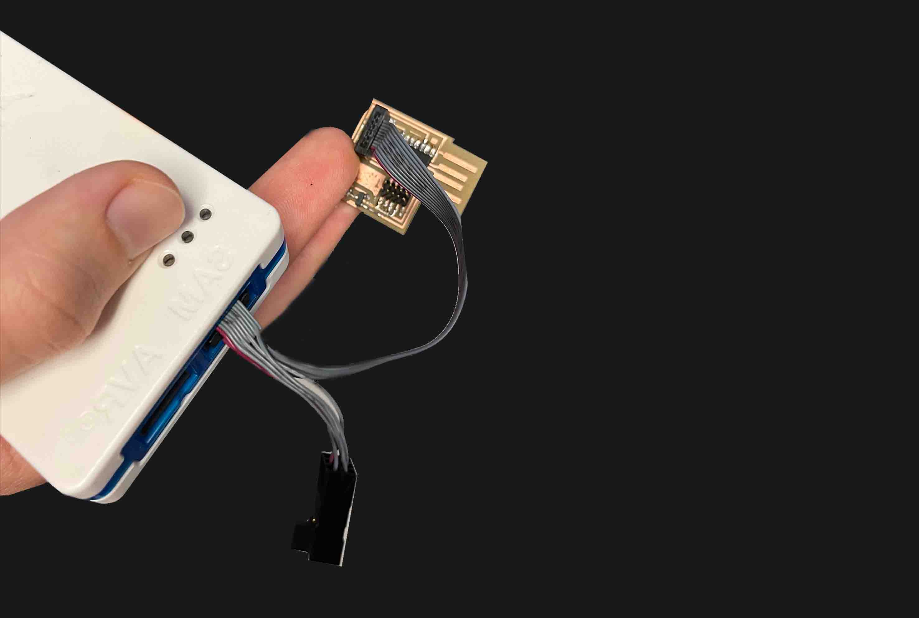
The first time didn't work, nor the second. I realised I had bridged two traces by mistake. I used the air gun to remove the specific component and re-soldered it properly.