08 Input Devices
This week I made a capactitve touchpad with an ATTiny1624 microcontroller, which measures input voltage on four pads using multitouch step-response.
Tools: Fusion360, PCB Milling Machine, Soldering Irons, Arduino, Python
VIDEO
Circuit Design
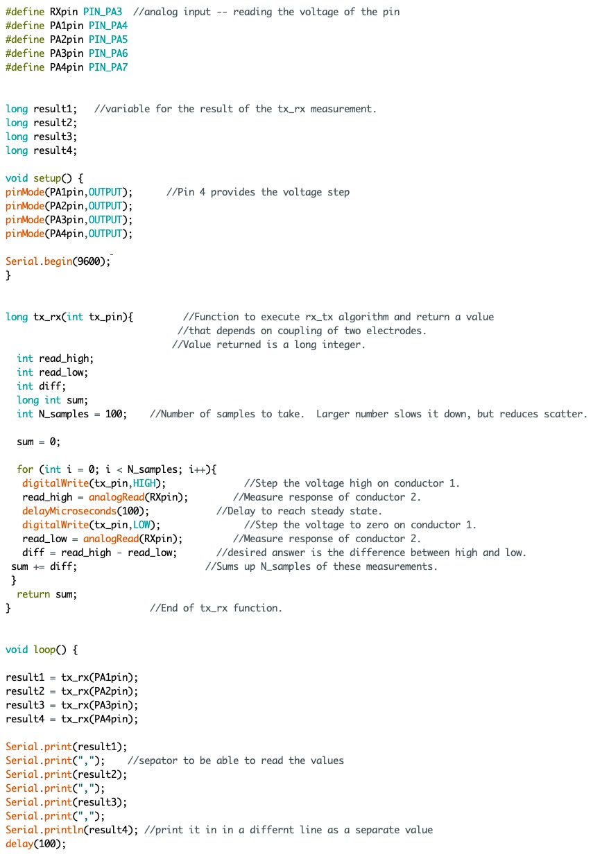
I have taken as reference Neil's example,
in which he uses a voltage divider to measure the differences between two parallel
capacitive plates separated by a non-capacitive material.
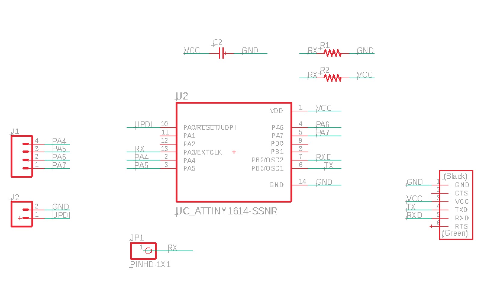
My design has four capacitive plates, so I have placed four outputs, one for each of the plates.
The input here will be the capacitive plate,
with respect to which I measure the difference in capacitance of the other four.
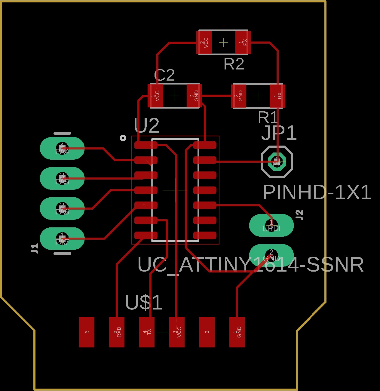
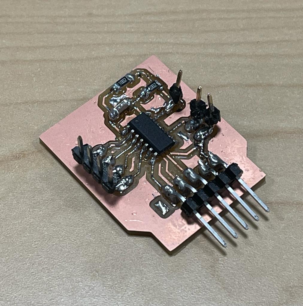
Once the PCB is designed, I milled the blank red cooper PCB and soldered on the components, and following used my UPDI programmer to program the ATTiny1624.
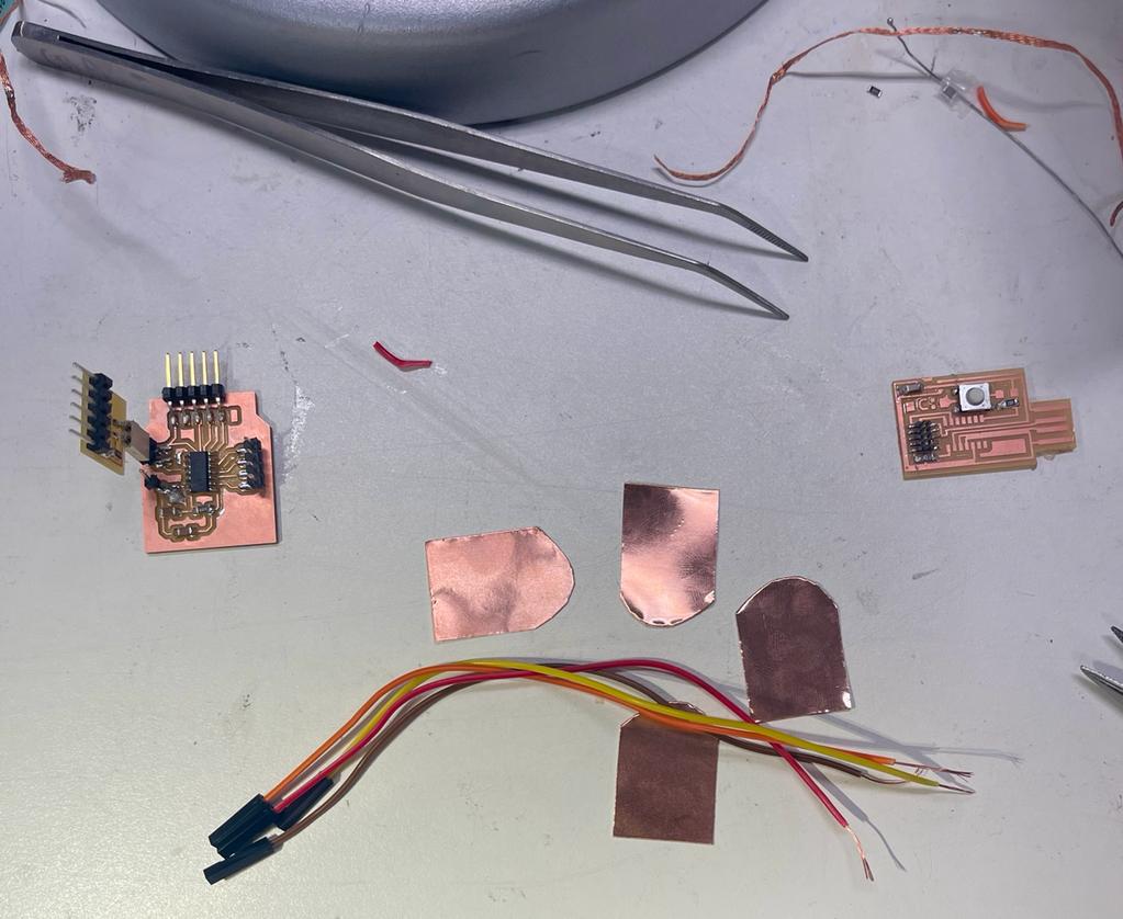
Touchpad design and Programming
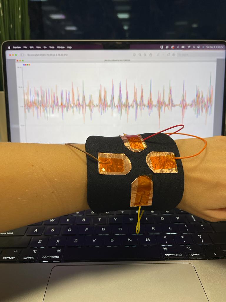
The input capacitive plate is located below the other four, with a size that cover the four with inset of a few mm. See here the back oh the house!
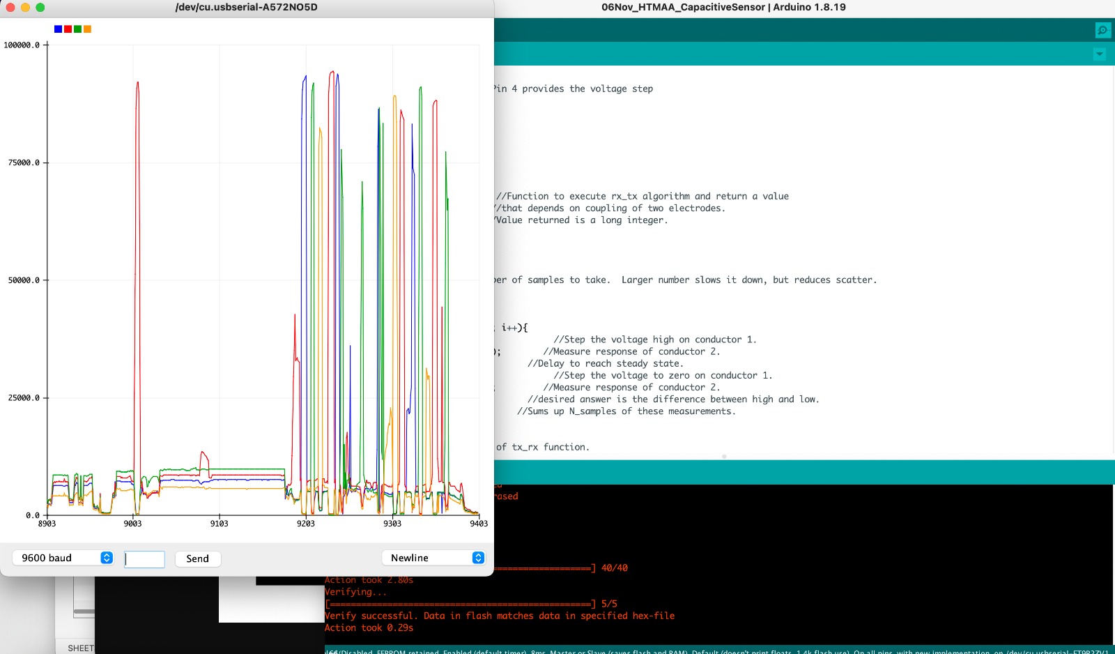
Even thought I was receiving four different values, they were floating voltages values.
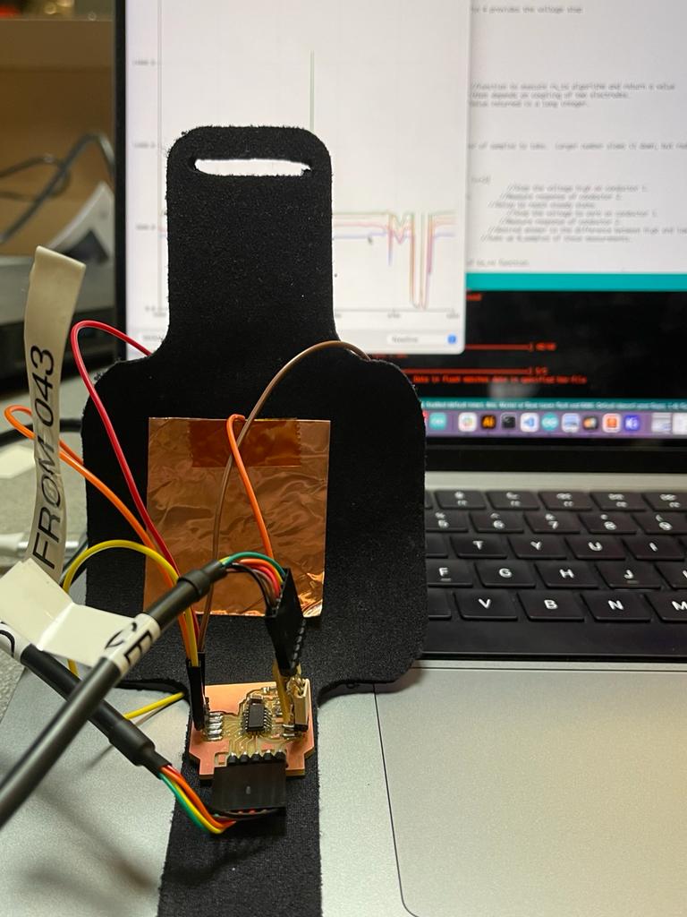
I think that the connection of the input pin with Ground was not working for me.
The pin was very loose on the PCB because I had drawn the paths between components too fine (.15 mm)-- next time drawing them at least .3 mm.
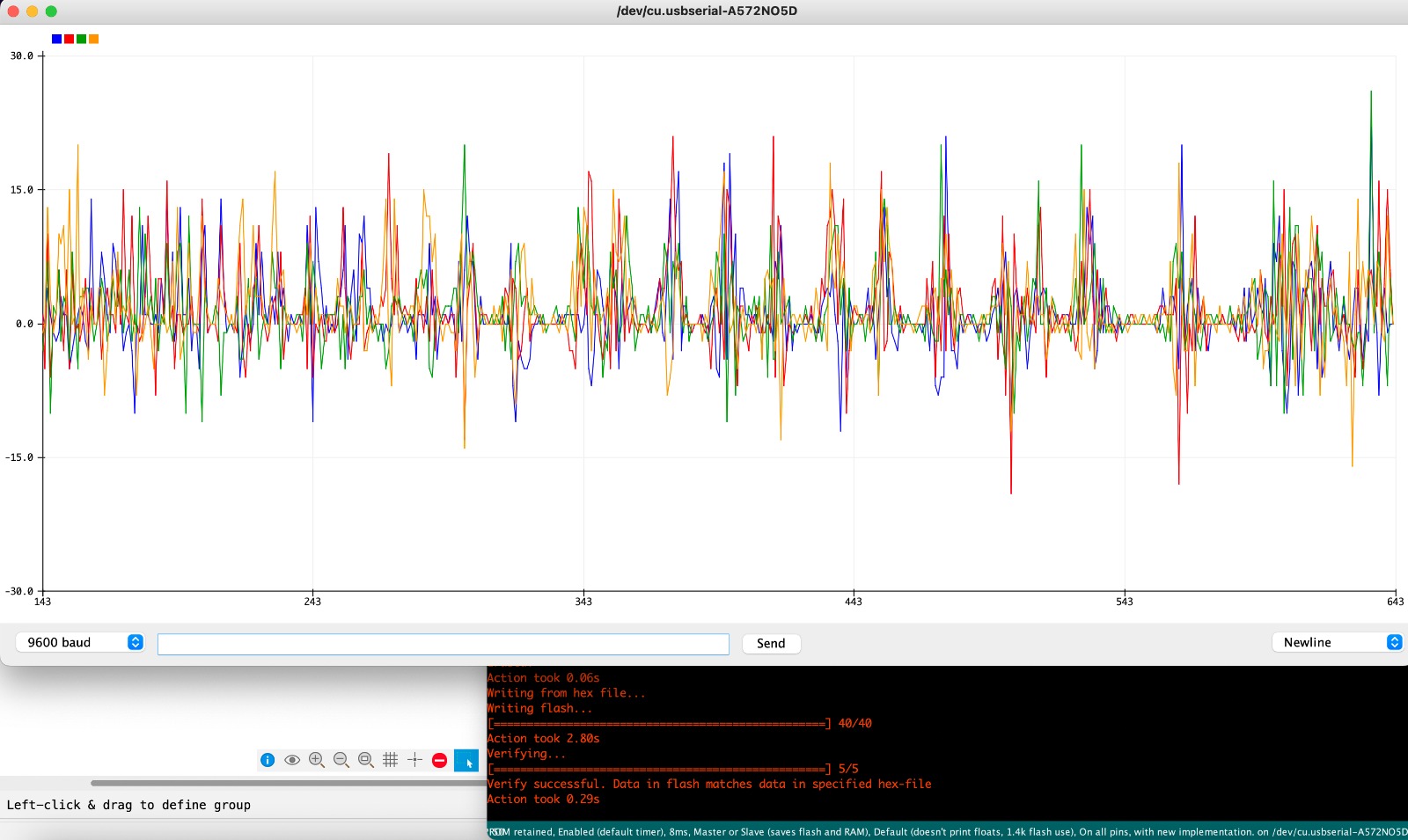
Once this was fixed, I uploaded the program, and it worked!
I used as a reference Neil's step response-code and Miana's.