09 Output Devices
The assignment for this week was to add an output device to a microcontroller board I designed, and program it to do something.
Tools: Fusion360, PCB Milling Machine, Soldering Irons, Arduino, Servo Motors
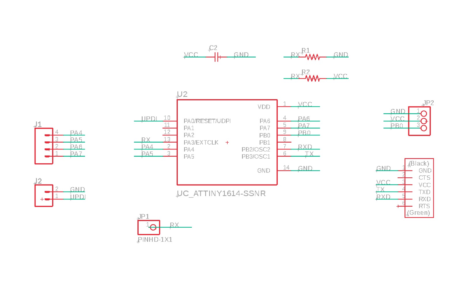
As I wanted to make some modifications to the input week board, I took advantage of this one to additionally include three pins to connect a servo as an output.
Also, since last time I had some little problems with the traces and spacing,
I'm including the fab2.dru from the Eagle library to set the design rules so that the traces & spacing would be large enough to be milled in the cba.
I used a lower-voltage motor (H-King HK SCM 16, 6V, single chip digital motor).
This motor works with voltage anywhere between 4.8V - 6V,
so the 5V powered from my existing PCB board. Below are a few additional specs for the motor:
HKSCM16-6 Single Chip Digital Servo (6V)
Spec.
Torque: 1.3kg @ 4.8v, 1.5kg @ 6v
Speed: 0.23 / 60deg @ 4.8v, 0.19 / 60 deg @ 6v
Voltage: 4.8v~6v
Type: Digital
The motor has three different lines, one for power (VCC), one for ground (GND),
and one for digital pulse width modulation input. I added a 3 pins feather (named JP2).
Find the schematic below:
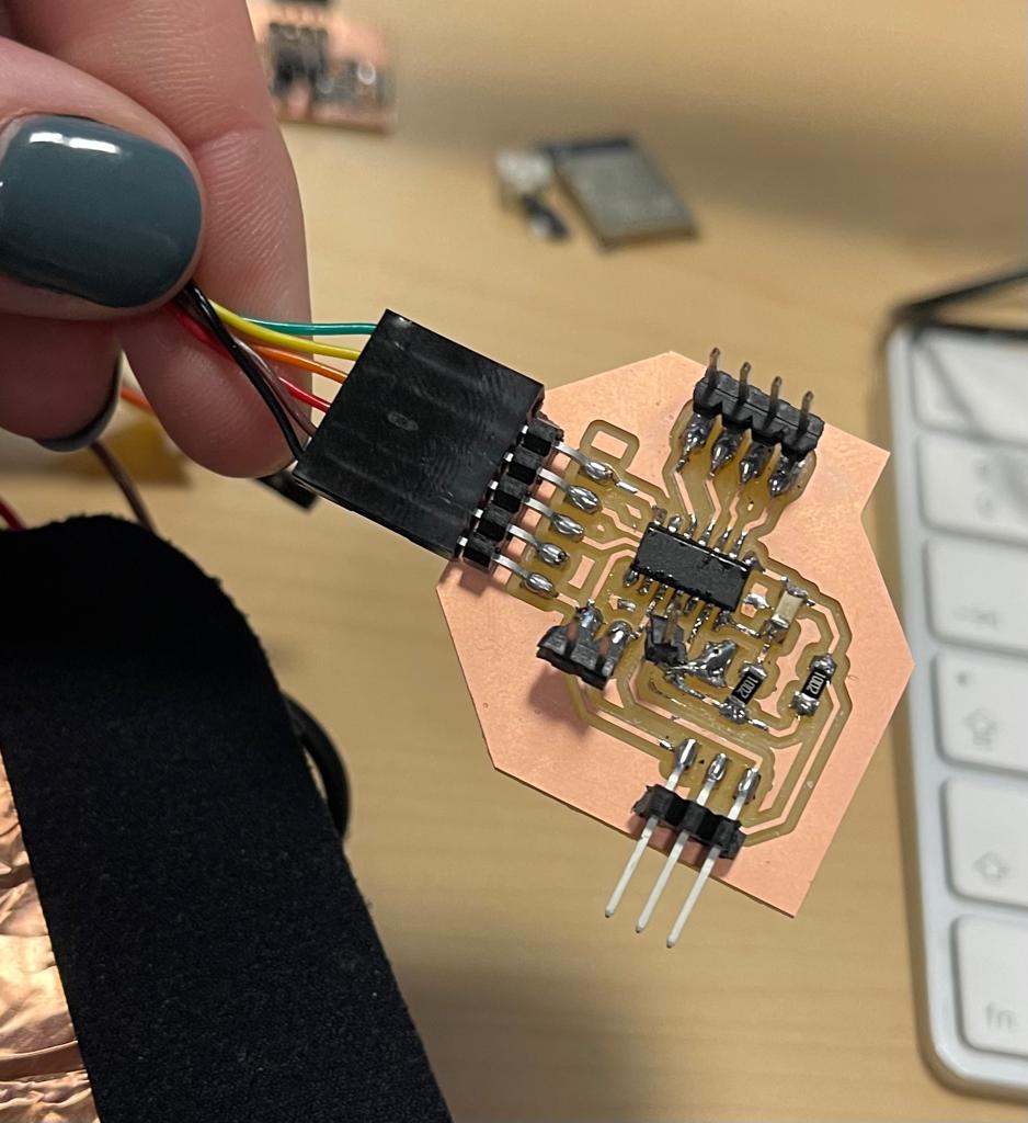
Bellow the resulted PCB:
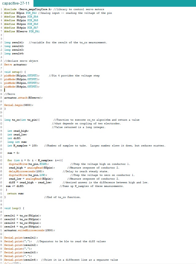
And finally I correlated the motor movement to the capacitive sensor as input.
I used Dave's code for the Low Pass Filter sensor reading, and cleaned up the noise from the capacitive sensor input.