NEPTUNE: Selective Photopolymerization of Photoresponsice LCEs by Direct Laser Writing Machine
For the final project, I decided to go completely out of my comfort zone and work in an area of long-standing interest: light activated liquid crystal polymers. Towards the final project I will be exploring the following:
- A light-responsive linear liquid crystal polymer(LLCP) -based film/ribbon/fiber actuator and taking the challenge to make these one-way actuators two-way;
- Explore liquid metal embedded LCEs
- A preliminary desktop direct laser writing machine for selective crosslinking;
- A light activated sheet swatch (if there's enough time);
- Bonus: an application using shape morphing LLCP films

Synthesizing Light-actuated LCPs
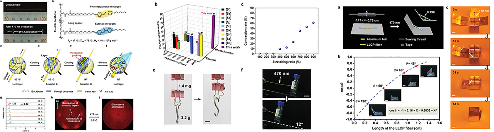
Liquid crystalline polymers can be classified into main chain, side chain and combined. This classification is based on the place in the polymer where the mesogen is inserted, i.e. within the main chain, as side groups, or both within the main chain and as side groups. A sub-class of liquid crystal polymers, Linear Liquid Crystal Co-polymers, have been recently synthesized combining shape memory effect and photochemical phase transition, to realize light-driven contraction as large as 81% (Reference Paper)
Despite their attractive mechanical characteristics, such as high strain and stress output as well as being untethered due to photoresponsivity, at the current stage these actuators are irreversible. However this may be possible with a novel synthesis introducing another polymer block to the LLCP composition. Although this is a very risky project, it might also be quite high impact. Working with fluid and thermally driven actuators before, my interest for this particular pathway comes from a curiosity and opportunities to work with light-activated systems, and their applications.
LIQUID CRYSTAL ELASTOMERS (LCEs) - Text from Fiberobo paper co-authored w Jack Forman
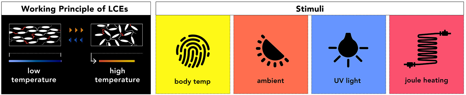
Liquid crystals are most known for their use in liquid crystal displays. While the reconfigurability of liquid crystals is well developed, an emerging frontier in programmable matter concerns liquid crystal elastomers. These solid elastic materials incorporate liquid crystal molecules to create morphing elastomers with high degrees of actuation ~40% and low hysteresis. Thus, LCEs are an attractive alternative to shape memory alloys, which require extensive training for two-way actuation, exhibit high hysteresis and must be coiled to enable actuation above 5%. LCEs are mechanically compliant and exhibit shape memory properties. These properties invite applications within human-computer interaction, including artificial muscles and developable surfaces. Unfortunately, unfavorable characteristics such as actuation speeds on the order of minutes, high transition temperature (60-150°C), and bulky structure have limited LCE integration into objects with which people will safely and comfortably interact with.
LCEs are rigid liquid crystal molecules (mesogens) within a rubbery plastic (elastomer) network. The alignment of the mesogens within the elastomer during material synthesis enables reversible switching between two domains; 1) a highly ordered (i.e., anisotropic) phase where the mesogens are aligned and 2) a disordered (i.e., isotropic) phase. As the material moves from the anisotropic to the isotropic state, it becomes optically clear and contracts. Transitioning between the phases can be induced by many stimuli including heat, UV light, visible spectrum light, or electric fields .
LCE PREPARATION - Text from Jack Forman's Fiberobo paper
Fifteen grams of RM82 and .105 g of BHT are added to a glass vial and placed in a 110°C toaster oven for 30 minutes (until completely melted). 4536 μL of EDDET are added to the vial and briefly vortexed before adding 800 μL of TATATO and mixing again. The vial is returned to the oven for 30 minutes until completely clear and liquid. After adding EDDET or TATATO the solution may cool, become opaque, and resolidify but can be remelted in the oven. Next, 0.42 g of I-651 is gently ground with a mortar and pestle, added to the vial, then vigorously mixed and poured into a polycarbonate syringe. Finally, 100 μL of DPA is added to the syringe and vigorously mixed before centrifugation at 3,000 RPM for 5 minutes to remove air bubbles. If a centrifuge is not accessible, the resin should be degassed in a metal vacuum chamber on a heated pad at 80°C.
SAFETY - Text from Fiberobo paper co-authored w Jack Forman
First, the resin synthesis should be performed in a fume hood with gloves, a coat, and glasses. However, once the resin is prepared, it is non-hazardous, as several works have studied the biocompatibility of LCEs. For a composition that is nearly identical to the one used in this current work, Yakacki et al. found no cytotoxicity for both the sheet resin and the fully cured LCE. Further studies have supported this claim saying, “these findings are strong evidence towards verifying LCEs as a safe and stable material for use in physiological conditions and fulfilling applications as a biomaterial”. However, further studies are needed to validate this claim fully. Still, we advise treating the crosslinking machine like a resin 3D printer: no eating around it, wearing gloves and a lab coat, and washing hands afterward. Once cured and solidified, the LCE sheets can be handled and worked with normally. As a note, the fully cured fiber has no discernible smell providing qualitative evidence of near-complete crosslinking.
A mild hazard is that UV eye protection should be worn when observing the 395 nm UV lights used to cure the fiber. As a result, we use UV protective glasses when the door is open. We also built an acrylic enclosure with an inexpensive yellow film that blocks 99% of UV light allowing close crosslinking observation without glasses.
MATERIALS - Text from Fiberobo paper co-authored w Jack Forman
- 1,4-Bis-[4-(6-acryloyloxyhexyloxy)benzoyloxy]-2-methylbenzene (RM82): A reactive liquid crystal compound known as mesogens
- Bis-[4-(3-acryloyloxypropyloxy)benzoyloxy]-2-methylbenzene (RM257): A reactive mesogen that can be combined with RM82 to lower the actuation temperature
- 2,2-(ethylenedioxy)diethanethiol (EDDET): A joining molecule that links mesogens together into elongated chains
- 1,3,5-triallyl-1,3,5-triazine-2,4,6(1H,3H,5H)-trione (TATATO): A common vinyl crosslinker that connects the chains to form an elastic network
- Dipropylamine (DPA): A chemical initiator that catalyzes the first reaction where mesogens are linked into long chains resulting in a viscous resin that can be extruded and drawn
- 2,2-dimethoxy-2-phenylacetophenone (I-651): A photoinitiator that, when exposed to UV (365nm) light, starts the second reaction where TATATO binds the chains together, solidifying the fiber. Note: the photoinitiator must be stored in a dark area to avoid premature initiation
- Butylated hydroxytoluene (BHT): A reaction inhibitor that extends the shelf life of the resin
EDDET, TATATO, BHT, I-651, and DPA were purchased from Sigma Aldrich. GDMP was purchased from Fisher Scientific. RM82 and RM257 were purchased in small quantities from Sigma Aldrich and in bulk from Daken Chemical.
INITIAL RESULTS OF LCE FILM ACTUATORS
Here's how two different width LCE films respond to 100°C as my heating gun unfortunately doesn't go below 100°C.
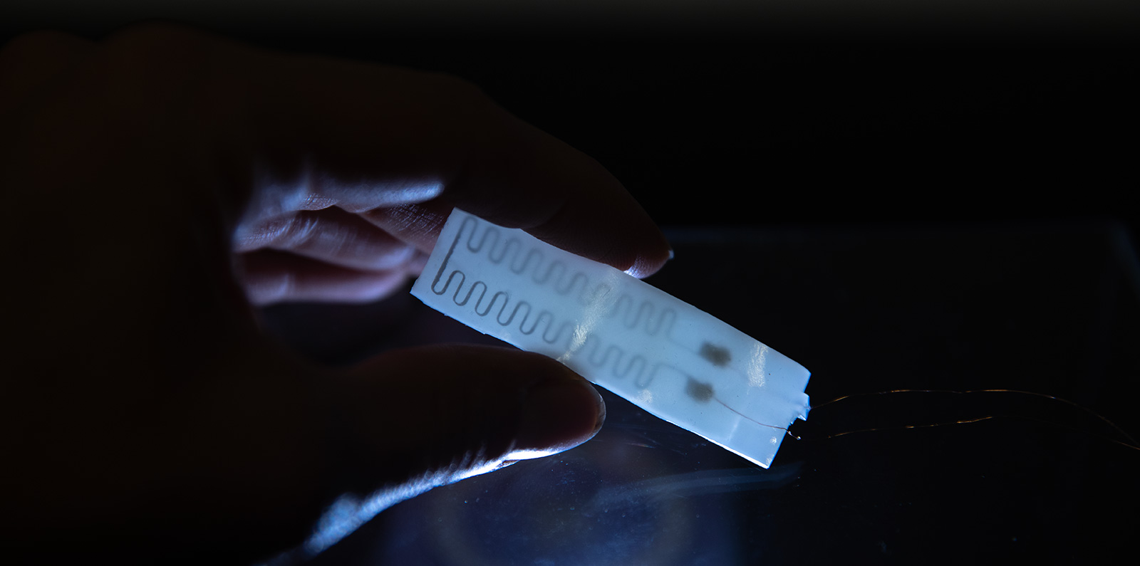
INITIAL RESULTS LCE-LM FILM ACTUATOR
LEFT FOR FUTURE: INTRODUCING LIGHT-RESPONSIVE MESOGEN
After successfully fabricating self-reversing thermal actuators, next step is to start synthesizing (1) photothermal and (2) photoisomeric actuators that either respond to ambient light or UV light at different wavelengths that can be programmable. Recently I found a paper, where researchers introduce light nanorods to LCE, and achieve repeatable and reprogrammable shape morphing by photo reaction. This process seems more familar to me than the azobenzene-LCE fabrication for photoisomeric response, hence I may revert my initial idea of making photoisomeric actuators to photothermal actuators.
Most of these capabilities depend on the photothermal effect of CNTs. Even though CNTs work very well in the previously described CNT-xLCE materials used for the construction of various dynamic 3D structures,26,28 CNTs, as well as all other kinds of inorganic nanoparticles such as gold nano-rods29 and graphene,30 are easy to aggregate in polymeric materials.31
FINAL PROJECT IDEA REFLECTIONS
After my presentation last week, Neil suggested that I may in fact make a test instrument instead of an application with these actuators. I love the idea but I'm not sure if I will be capable of doing it so I will do some more research on this.
On the other hand, early on when I was working with the polymer, I had a fun accident where at the final UV cross-linking stage I had irridated only one side of an LCE fiber I had spun, hence I ended up with a coiled LCE structure as below!
So this got me thinking that one could use this "accident" for their benefit and crosslink parts of the polymer and leave others loosely cross-linked. In order to see larger and more complex effects of such a selective cross-linking process, I decided to work with sheet LCEs instead of fibers. As the last stage UV crosslinking is a necessary part of the process, by building this machine, I will be able to fully cross-link or selectively cross-link different form factors of samples in the long run. So it makes a great research tool for me (and hopefully for others working in the same area)!
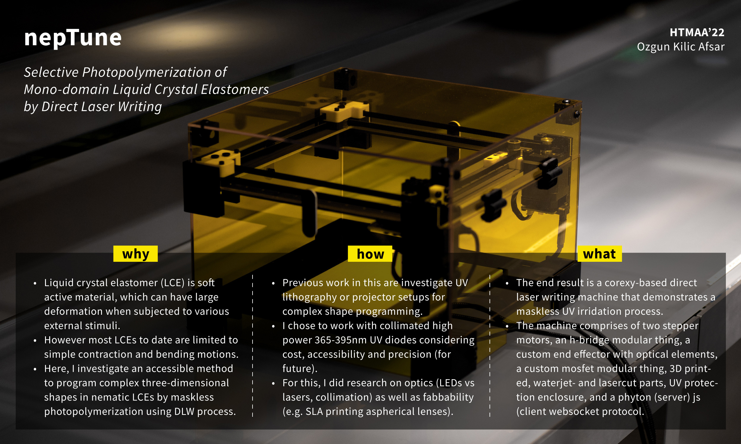
UPDATED FINAL PROJECT IDEA: SELECTIVE PHOTOPOLYMERIZATION OF LCE FILM ACTUATORS WITH CORE XY UV LASER SETUP
My main goal is to build a versatile and fairly accesible fabbed setup with a modular end effector for different photoresponsive processes with polymer resins. With these aims in mind, I used mostly fabbable materials and processes in the machine.
Below are the subsystems required to achieve the goal. Further, for testing of the machine, an LCE film sample need to be molded and casted at a suitable thickness (ideally below 500 microns for seconds of response time)
- System 1: core xy laser plotter
- System 2 (OPTIONAL): biaxial tensioning mechanism (https://www.instructables.com/Universal-Tensile-Testing-Machine-VERSION-TWO)
- System 3: collimated light beam using UV lightsource (led or laser?)
Background (Related Works)
Of course I'm not the only one who thought about this before. Researchers had different approaches to realize complex morphing structures with LCEs (e.g. https://onlinelibrary.wiley.com/doi/full/10.1002/aisy.202100065). Some of these works include digital light processing (DLP) using a UV projector setup (e.g. https://www.nature.com/articles/s41598-022-22556-8). Others have explored using different photoinitiators in different sections of the elastomer so that they would crosslink only when exposed to the suitable UV wavelength.
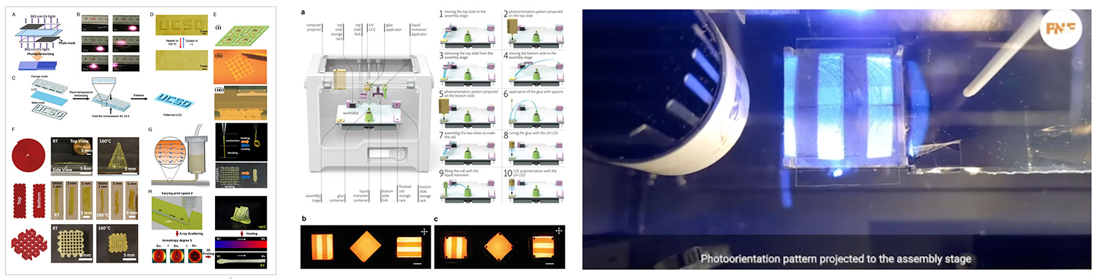
The second approach is quite involved however the projector setup has a lot of benefits in exposing the material to the designed crosslinking pattern simultaneously. However homogenous intensity of exposure and resolution when compared to laser writing processes is still questionable. Further, for my case, I wanted to make a more versatile machine which will grow further on this first prototype. For example, with a projector setup, it is currently not possible or easily achivable to irridate a 3D polymer object. However with a laser setup, one can use micromirrors or a rotating and effector to achieve similar process in 3D form factors.
Research on UV Lasers: Cost and Safety Concerns
As I haven't worked with UV lasers before and neither with optics, I consulted with Jan to get his opinion after my initial search on UV lasers. The research and consultation part took quite a bit of time to settle on the final choice of components that will make the UV light source and optical setup. Here are my takeaways:
- Deep UV (395nm and below) lasers are freaking expensive to the point of 4 or 5 digit USD so that's not an option
- UV lasers are scary and need to be handled carefully after careful consultation with the EHS
- Although small diameter collimated beams are much easily achievable with lasers, there have been instances of using high power LEDs as an alternative
- Jan gave me the most awesome idea of 3D printing my own lenses using Formlabs clear resin (and quite and arduous but worth it post-processing!)
Hence, I ended up deciding to build my own optical setup using a high power 365nm UV led which became a core part of the project which will be detailed further below.
DESIGN PROCESS
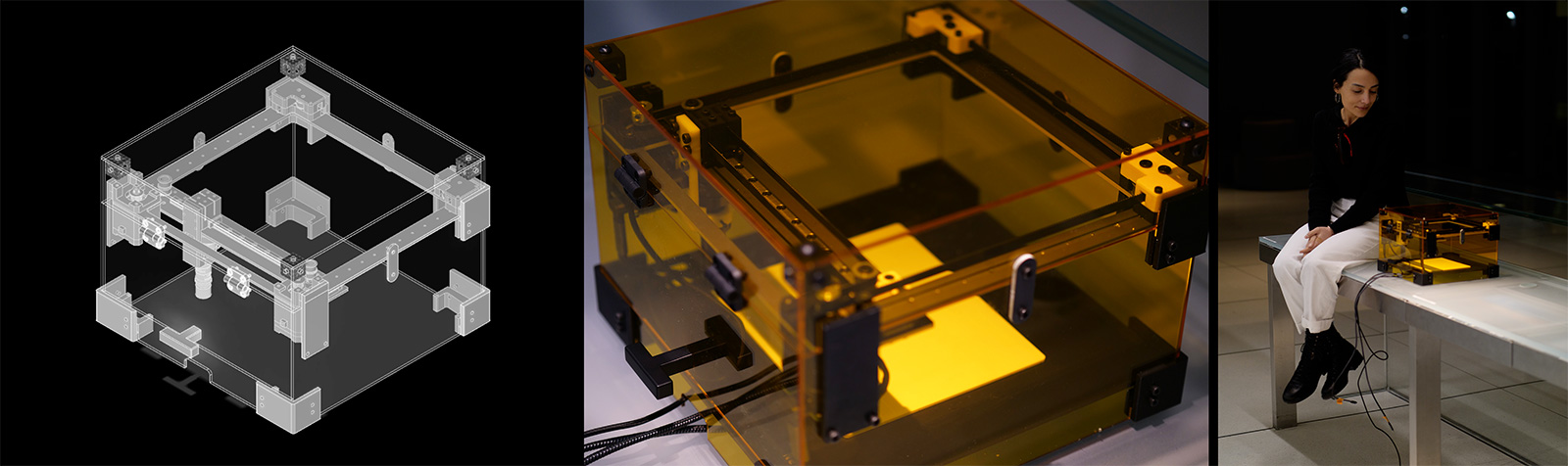
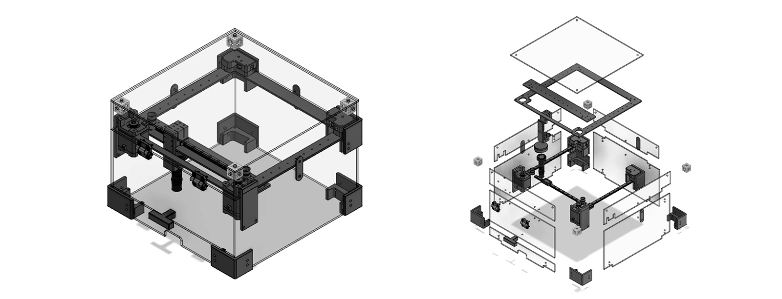
I started of by re-designing the stage based on David's parametric corexy design. Since I would need some distance for the light source and the aspherical lens, I left a generous amount of space underneath the xy stage. This was also a choice due to being able to add a biaxial tensioning mechanism at the bottom of the machine since LCE needs to be tensioned up to 200% (or less) during the crosslinking stage.
Materials and Components
Above are screenshots of the machine design and exploded view from Fusion 360. Parts were designed to be either laser cut, 3D printed or waterjet cut. Except for the door handle, door hinges, stepper motors, high power diode, and hollow lens tubes the rest of the machine is completely built by subtractive or additive processes.
Purchased Parts and Costs
Here's BoM of purchased parts and their costs:
- Anodized steel door handle - Amazon, 8 USD
- Polypropylene hinges - McMaster Carr, 6 USD (each)
- Stackable lens tubes - Thorlabs, 12 USD (each)
- Threaded adapters - Thorlabs, 22.37 USD (each)
- Nema 17 Stepper motors - Stepperonline, 14.65 USD each
- Anodized aluminum sheet metal - McMaster Carr, 19.65 USD
- 3mm UV protective acrylic - MakerStock, 23.95 USD
- High power UV LED - Digikey, 11.48 USD
- Linear rails - THK, 44 USD (each)
Fabbed Parts
The remaining parts are fabbed using either additive or subractive processes. For housing, I used 99% UV protective 3mm acrylic sheets,
Fabrication Processes
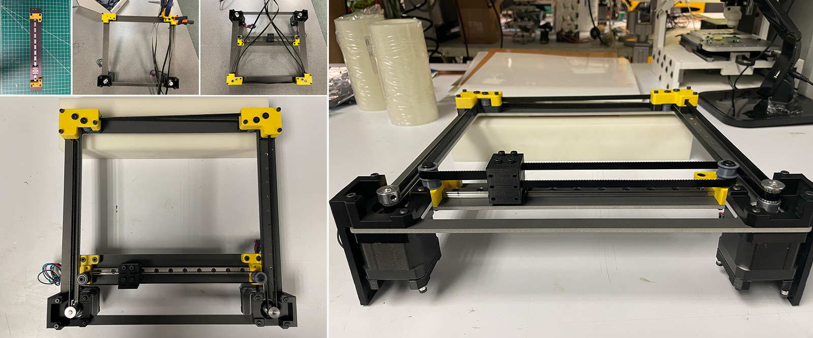
CoreXY Stage
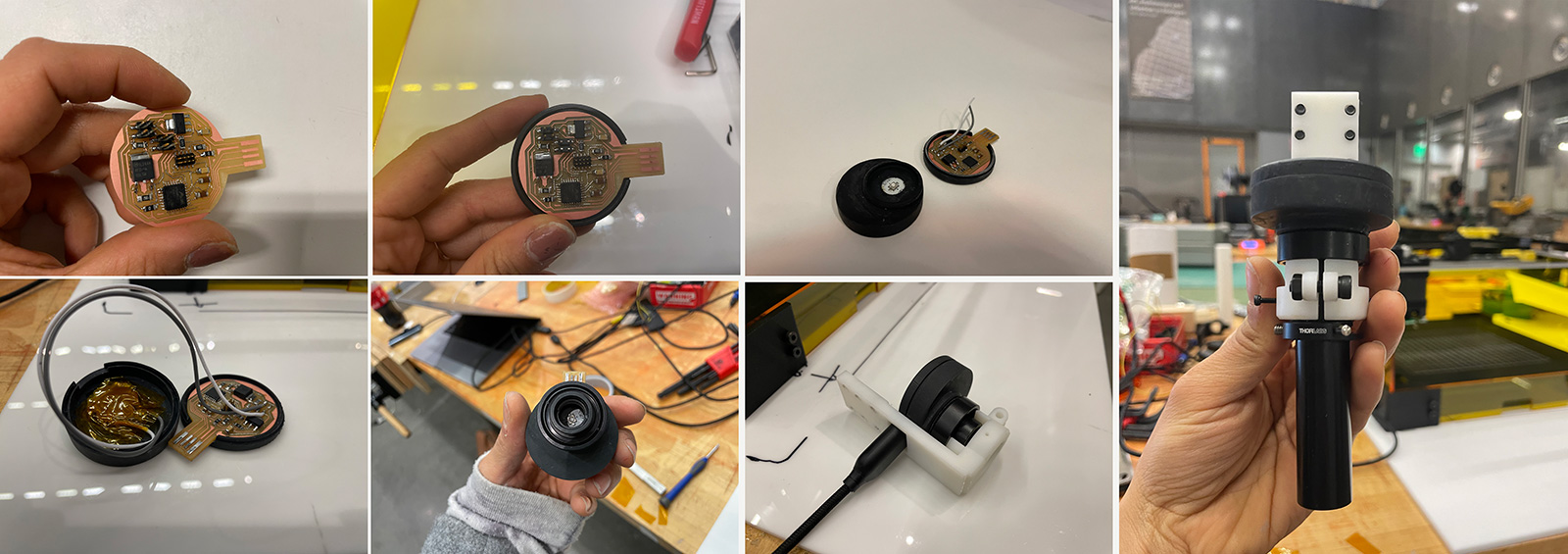
My_mosfet (modular thing) + power led
SLA Printed Aspherical Lenses
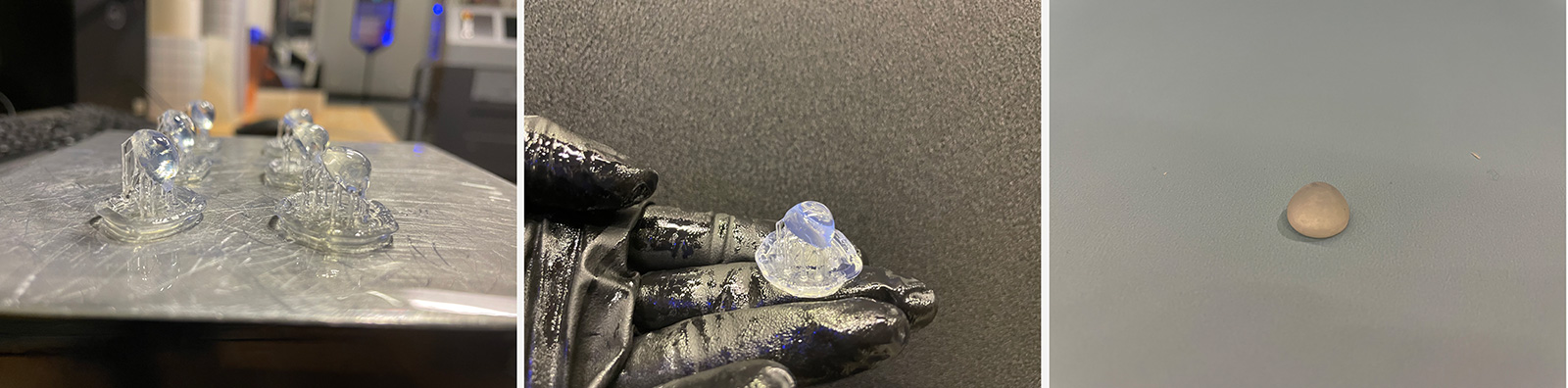
Following the Formlabs tutorial, I designed and printed aspherical lenses, and after proper post processing from 400-12000 grit sanding, polishing, and re-dipping into clear resin, I got a quite cool result as seen below! I'm very interested in further improving this process with less manual polishing in the next steps, as it looks quite promising.
3D Printed Lens Fabrication Steps
This process is a slight twist from the Formlabs tutorial:
- 1. Use this free software for your lens design: https://arachnoid.com/OpticalRayTracer/
- 2. Place the 3D model at a 30° angle relative to the build platform, with supports placed only along the edge of the lens (to prevent support marks on important lens surfaces)
- 3. Finishing: Manual wet-sanding + dipping
- 3.1 Manual sanding: use a range of sandpaper with grits from 400 to 12000, in increments of 200. I did wet-sanding, which is sanding the lens under warm, running water (or in a warm water bath). This avoids heavy surface scratches. Do this process slowly and with cleaning/polishing the lens in-between every 200-grit step, using Novus 2 fine scratch remover - you can buy from amazon)
- 3.2 Final polish: After 3000 grit, the lens should start to become clearer. At 12.000 it becomes clear, shiny and reflective. After 12.000 sanding is done, polish the lens with cotton cloth + Novus 1 Plastic Clean & Shine (also purchased from amazon)
- 3.3 Dipping: Hold the lens carefully from the edges using tweezers. Dip the top part of the lens in diluted clear resin, contained in a small petri dish or similar. Dilution is an important step in order to avoid (1) too thick of a coating layer, and also avoiding (2) bubbles from forming on the surface of the lens. Then post-cure under UV lamp as usual. Repeat the same process for the bottom side of the lens.
- At this moment you should be done and have a happy clear lens that behaves as in the video below!
OUTCOMES AND REFLECTIONS
Below are two videos demonstrating the machine writing the "positive" part of the mask in black onto the substrate. One is a stripe and the other is a donut shape. Here you will see that the beam size is large, around 2mm.
However due to having a mechanical pinhole, one can make the collimated beam much smaller as in the video below, in this case around 300 microns. The next step is to push this smaller for higher precision.
Questions Answered
I identified that high power leds provide a decent intensity as well as collimated beam as an alternative to laser diodes.
3D printing of aspherical lenses have huge potential and I should push this further.
A direct laser machine is a great tool to crosslink LCEs, and further selectively crosslink them for maskless lithography, hence removing the requirement of fabricating expensive masks.
Somethings worked, others were too ambitious...
I wasn't able to fully polish the lenses on time so I was a bit sad about that. Nevertheless, the class begins after it ends as Neil always says!
I wasn't able to also build the tensioning stage and that's why I couldn't demonstrate the actuating LCE with selective crosslinking. That's my immediate next step!
Evaluation
As for where the project reached, I'm pretty pleased with the result. My packaging was good and my machine worked seamlessly. Despite the missing parts that will allow me to go further with this idea, I believe the project was successful for its state.
Implications
During the open house, there were a lot of interest hence this shows me an accessible tool like thus would have positive impact on other researchers' works. This further strengthens my point of making a laser-based but still cheaper version of this with Jan for his FabuBox. I'm super excited for the future!
REFERENCES
- [1] Inhomogeneous stretch induced patterning of molecular orientation in liquid crystal elastomers: https://doi.org/10.1016/j.eml.2015.09.007
- [2] Varied Alignment Methods and Versatile Actuations for Liquid Crystal Elastomers (Review): https://doi.org/10.1002/aisy.202100065