INTRODUCTION

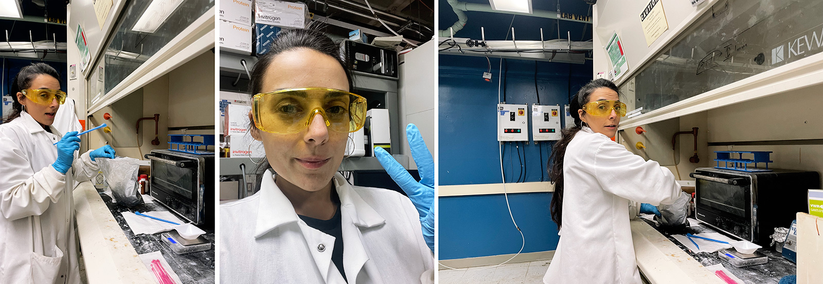
This week I worked on an output device that relates to my final project's fabrication process; a thermally responsive liquid crystal elastomer sheet/film. Finally, for the first time since I came to MIT, I made my way into the BL1 at CBA to continue polymer synthesis which I was looking so much forward to! Thanks to my amazing friend and collaborator and course TA, Jack Forman, who walked me through the steps of how to work in the CBA wetlab responsibly, I started familiarizing myself with the tools and processes of working with chemicals at CBA's BL1.
Most importantly, I completed my online training for Potentially Hazardous Chemicals by MIT's EHS, and as Neil suggested I will continue to check in with them prior to working with chemicals required for the photoresponsive polymers.
LIQUID CRYSTAL ELASTOMERS (LCEs) - Text from Fiberobo paper co-authored w Jack Forman
Liquid crystals are most known for their use in liquid crystal displays. While the reconfigurability of liquid crystals is well developed, an emerging frontier in programmable matter concerns liquid crystal elastomers. These solid elastic materials incorporate liquid crystal molecules to create morphing elastomers with high degrees of actuation ~40% and low hysteresis. Thus, LCEs are an attractive alternative to shape memory alloys, which require extensive training for two-way actuation, exhibit high hysteresis and must be coiled to enable actuation above 5%. LCEs are mechanically compliant and exhibit shape memory properties. These properties invite applications within human-computer interaction, including artificial muscles and developable surfaces. Unfortunately, unfavorable characteristics such as actuation speeds on the order of minutes, high transition temperature (60-150°C), and bulky structure have limited LCE integration into objects with which people will safely and comfortably interact WITH.
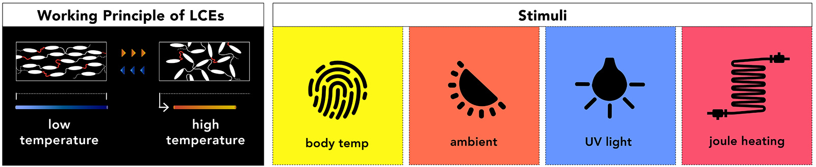
LCEs are rigid liquid crystal molecules (mesogens) within a rubbery plastic (elastomer) network. The alignment of the mesogens within the elastomer during material synthesis enables reversible switching between two domains; 1) a highly ordered (i.e., anisotropic) phase where the mesogens are aligned and 2) a disordered (i.e., isotropic) phase. As the material moves from the anisotropic to the isotropic state, it becomes optically clear and contracts. Transitioning between the phases can be induced by many stimuli including heat, UV light, visible spectrum light, or electric fields .
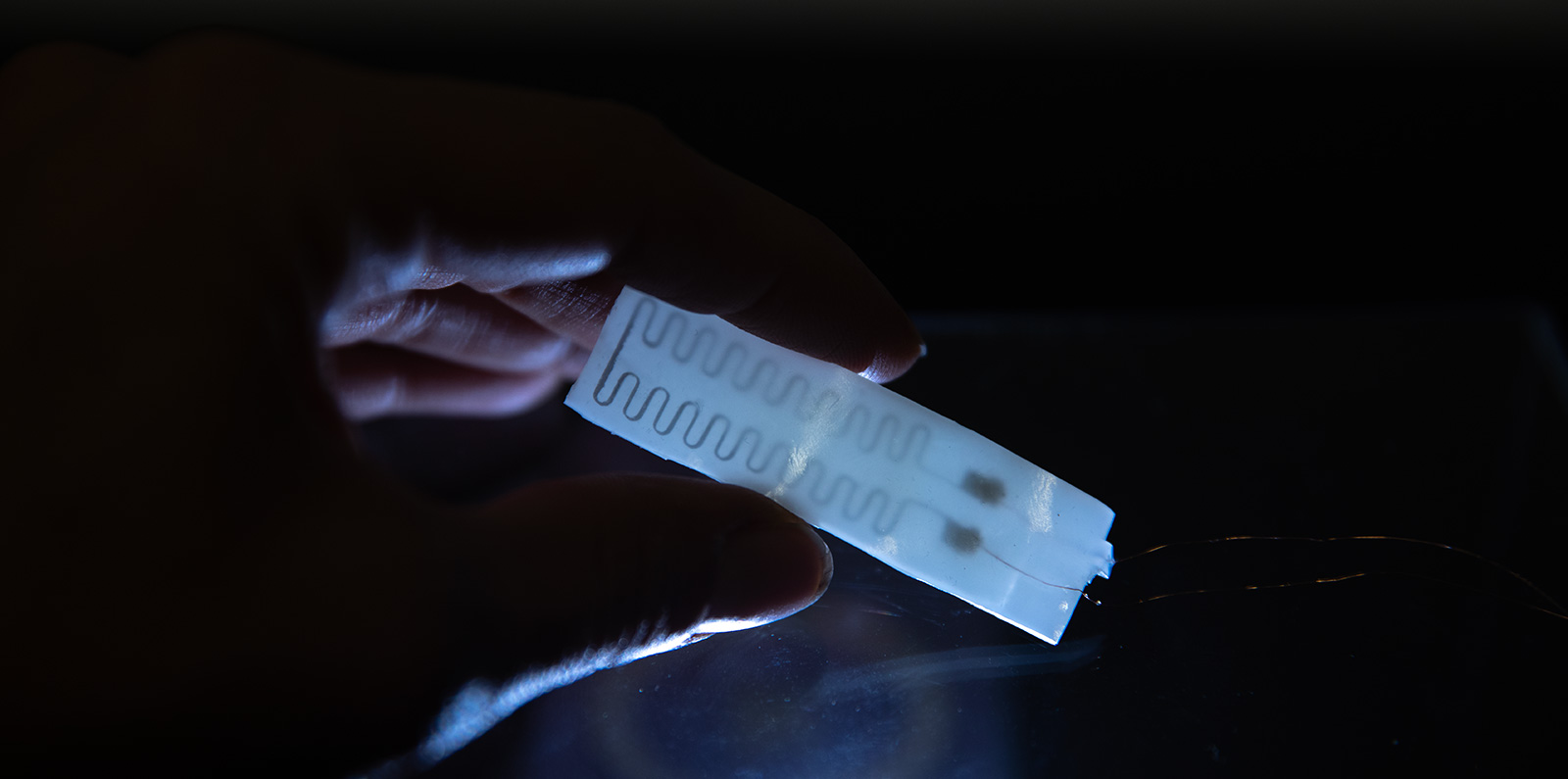
THERMALLY RESPONSIVE LCEs WITH EMBEDDED HEATING ELEMENT
Liquid crystal elastomer have attracted much attention recently due to theirlarge (~40%) and reversible actuation, high processability, and programmability. For thermally responsive LCEs, as the temperature increases, liquid crystal mesogens transition from the nematic phase to the isotropic phase (see above diagram), leading to a notable and macroscopic deformation in the material.
A variety of LCE-based actuating structures have been designed and successfully fabricated, which are often actuated by direct environmental heating or by light through photothermal and photochemical effects. However, for most practical applications, electronically powered actuators provide notable convenience for system control and integration. A few recent studies have successfully integrated stretchable resistive heaters into LCE, whose actuation can then be easily controlled by electrical potential. Here, I wanted to pursue a fairly accessible route of fabrication (not yet for LCE prep) for embedding stretchable liquid metal heaters in thin film LCE for electrical heating to achieve (1) a contracting LCE-LM film actuator, a bilayer bending actuator with an LCE-LM-PDMS multilayered structure.
LIQUID METALS
Soft and stretchable sensors have the potential to be incorporated into soft robotics and conformal electronics. Liquid metals represent a promising class of materials for creating these sensors because they can undergo large deformations while retaining electrical continuity. Incorporating liquid metal into hollow elastomeric capillaries results in fibers that can integrate with textiles, comply with complex surfaces, and be mass produced at high speeds. Liquid metal can be either directly printed or injected into hollow and extremely stretchable elastomeric hollow channels and the resulting sensors can be used for resistive or capacitive sensors of torsion, strain, and touch.
Gallium-based LMs, such as eutectic gallium indium (EGaIn, 75% Ga and 25% In), offer a promising way to create such sensors.[10]EGaIn has low toxicity,[11] negligible vapor pressure at room temperature, and low viscosity. The latter property allows LM to flow in response to deformation, whereas solid metals are stiff and prone to fail at small strains. Embed-ding LM in elastomer decouples the elec-trical and mechanical properties; that is, these composites have the electrical prop-erties of the metal and the mechanical properties of the elastomer.
MATERIALS - Text from Fiberobo paper co-authored w Jack Forman
- 1,4-Bis-[4-(6-acryloyloxyhexyloxy)benzoyloxy]-2-methylbenzene (RM82): A reactive liquid crystal compound known as mesogens
- Bis-[4-(3-acryloyloxypropyloxy)benzoyloxy]-2-methylbenzene (RM257): A reactive mesogen that can be combined with RM82 to lower the actuation temperature
- 2,2-(ethylenedioxy)diethanethiol (EDDET): A joining molecule that links mesogens together into elongated chains
- 1,3,5-triallyl-1,3,5-triazine-2,4,6(1H,3H,5H)-trione (TATATO): A common vinyl crosslinker that connects the chains to form an elastic network
- Dipropylamine (DPA): A chemical initiator that catalyzes the first reaction where mesogens are linked into long chains resulting in a viscous resin that can be extruded and drawn
- 2,2-dimethoxy-2-phenylacetophenone (I-651): A photoinitiator that, when exposed to UV (365nm) light, starts the second reaction where TATATO binds the chains together, solidifying the fiber. Note: the photoinitiator must be stored in a dark area to avoid premature initiation
- Butylated hydroxytoluene (BHT): A reaction inhibitor that extends the shelf life of the resin
EDDET, TATATO, BHT, I-651, and DPA were purchased from Sigma Aldrich. GDMP was purchased from Fisher Scientific. RM82 and RM257 were purchased in small quantities from Sigma Aldrich and in bulk from Daken Chemical.
RESIN PREPARATION - Text from Fiberobo paper co-authored w Jack Forman
Fifteen grams of RM82 and .105 g of BHT are added to a glass vial and placed in a 110°C toaster oven for 30 minutes (until completely melted). 4.536 mµL of EDDET are added to the vial and briefly vortexed before adding 800 µL of TATATO and mixing again. The vial is returned to the oven for 30 minutes until completely clear and liquid. After adding EDDET or TATATO the solution may cool, become opaque, and resolidify but can be remelted in the oven. Next, 0.42 g of I-651 is gently ground with a mortar and pestle, added to the vial, then vigorously mixed and poured into a polycarbonate syringe. Finally, 100 µL of DPA is added to the syringe and vigorously mixed before centrifugation at 3,000 RPM for 5 minutes to remove air bubbles.
THIN FILM MASKS FOR LIQUID METAL PATTERNING WITH CRICUT CUT SMART 2
MASK DESIGN
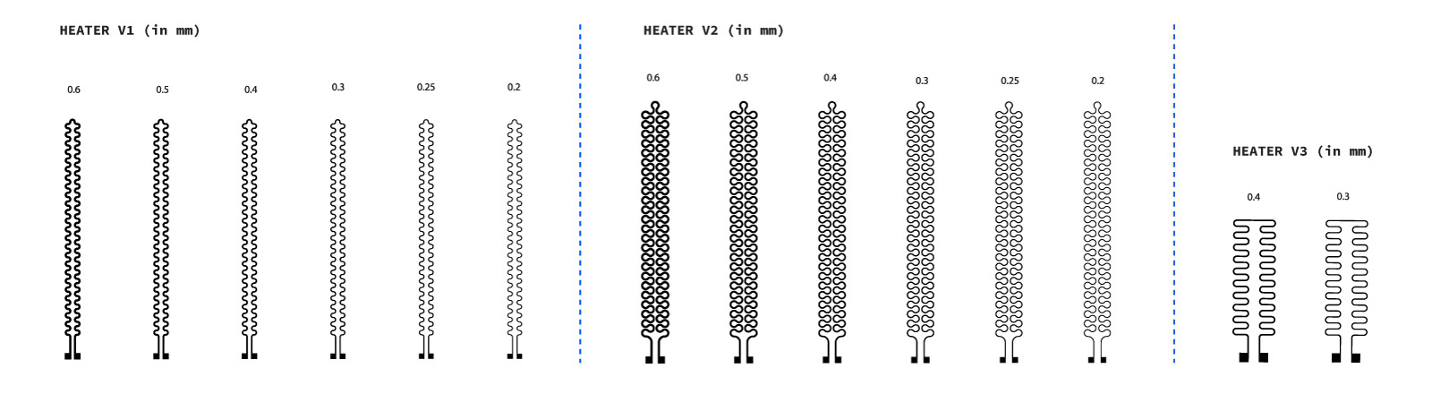
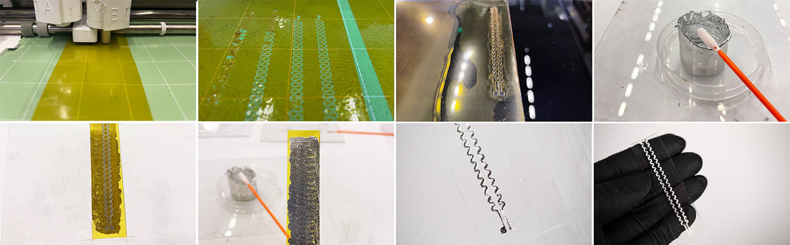
Considering that I was able to cut 200 μm thick linear channels with Cricut several weeks ago, I wanted to go ahead and try the same mask thickness for a heater. However due to having read bad stickiness on the cutting mats, all of my tests failed. I tried to initiate the adhesion by cleaning the mats with soapy water but it did not improve to the point that I had enough adhesion between the material and the mat so that my material does not get picked up by Cricut's knife, which is especially crucial during fine cuts. This was a bit frustrating but as soon as I realized I wouldn't be getting any results, I ordered different mats from Cricut; namely the regular and strong grip ones. This completely improved the process however 200 μm wavy channels were not coming out as homogeneous as linear channels. Hence I increased my channel size to iterations from 250 - 600 μm all of which resulted fine. The sharpest looking channel geometries were with 300 to 500μm details hence I proceeded with the two channel thicknesses.
For the fabrication process, I first laid out my film on the cricut mat carefully to avoid any air bubbles trapped between the film and the mat - this is crucial for an even cut. Then I uploaded my file, set my material setting to Iron+ and edited the material settings to 2x cut, which ensures a total cut out of the mask (figure 1 below). This was after tens of knife pressure / cut speed / cut times iterations that I achieved a successful result. I removed the positive sections of the cut to have the mask left on the mat (figure 1 below)
DUMMY TESTING ON SILICONE: ECOFLEX 30A, SYLGARD 184
The next step was to pour PDMS (Sylgard 184) over the film with the mask cut out. Once PDMS was cured on Prusa bed at 60 degrees, I removed the film from Cricut mat and transferred onto another surface (figure 3 below).
MAKING LIQUID METAL PASTE FROM PURE LIQUID METAL
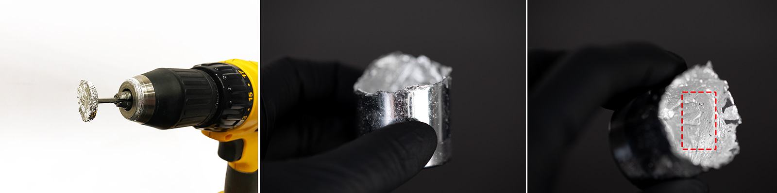
One of the challenging details of patterning with liquid metals (gallium-based alloys) is due to their high surface tension, they tend to form droplets. This makes it challenging to apply thin lines on the surfaces, even through a mask. One method is to make sprayable liquid metal by mixing solvents to reduce viscosity and make it sprayable, however I wanted to avoid using any solvents. Hence, I recalled a process from my previous lab, which was introducing more native oxide to liquid metal by stirring it at 5000 RPM for 15 minutes (better if longer). Since I used a drill for this, my arm could only take stirring fo 15 mins however I achieved a liquid metal paste from pure liquid metal! I tried applying it on a piece of PDMS I had and it worked brilliantly! The paste can be seen in the image below.
APPLYING THE PASTE WITH A Q-TIP
After ensuring that the mask sits on cured PDMS safely, I applied a little bit of paste over the channels using a foam end q-tip. Then I carefully removed the mask from the surface of the PDMS and got nice looking but somewhat thick LM channels. I measured the resistance across the pads to be 3 Ohms due to the thickness of the LM channels. Since this is too low of a resistance for a heater that draws reasonable power, I decided to go with thinner channels for the LCE test, which is 300μm.
MULTILAYERED ELECTRICALLY CONTROLLED LCE ACTUATOR (LCE-LM-LCE)
For the fabrication of a multilayered electrically heater LCE actuator, I defined a fabrication process that would allow me to work in the shortest time possible. The main hindering element in the loose cross linking process is the time it takes for polymerization due to the BHT content in the material. However, there's also a fall back of reducing BHT, which is that the polymer gets cured faster upon addin the crosslinker (DPA) and the shelf life of the material is shorter than 2 weeks. Hence I did not reduce the BHT but found a workaround that is exposing the loosely cross-linked LCE to UV light for less than a minute so that the polymerization is sped up. However it shouldn't be too long that the material is not completely cross-linked at a 0% strain state.
So the process goes as follows; (1) cast LCE sheet in a petri dish, (2) 30 sec. crosslinking under 365nm UV, (3) adding on the mask, (4) applying the LM paste and remove the mask, (5) add connector wires with silver epoxy, (6) pour the top layer LCE, (7) repeat step 2, and finally (8) pre-strain the multilayered structure to 80% its length and crosslink both sides under UV light for 30 mins each.
ADDING MASK ON LOOSELY CROSS-LINKED LCE FILM
After the epoxy is fully cured and ends are sealed, first I measured the readout resistance to be only 6 Ohms and the change in R at 100% strain was around 2.5 Ohms. To increase R(0) and sensitivity, twisting is used as a method to introduce a geometric "necking" behaviour in the tubing, as once the fiber is twisted, this will reduce the ID as well as create regions of stress on the LM channels. This is the main principle and reason behind introducing twisting to these fibers. In my case, I folded the fiber into two equal lengths, and first twisted the insulated connection wires to stabilize the connection part. After that, I inserted a thin stick to the other end of the LM filled tubing, and started twisting manually. This was done in a vertical setup, applying 20% stretch to the tubing while doing so.
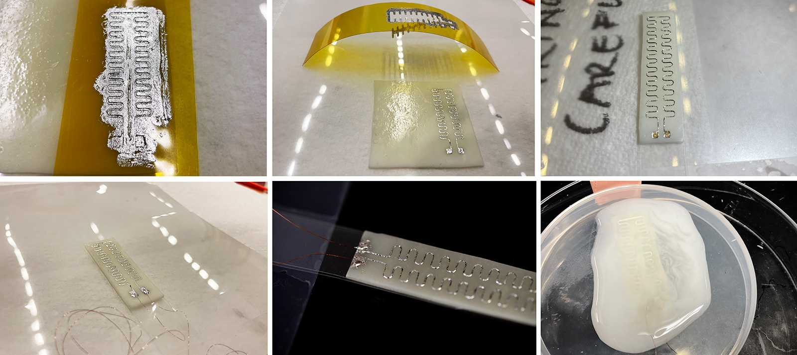
BRUSHING LM PASTE OVER THE MASK & ADDING CONNECTION WIRES
Through this process, it was also clearly observable that as the twisting turns were increased, the resistance increased. Hence, the fabricated sensor proves to be also a good torsional sensor for applications. However, strain and torsion cannot be decoupled and either one or the other will need to be used when applied to use cases. I observed the increase in resistance while applying 1, 5, 10, 20 and 30 turns. At 30 turns, the R(0) went up to 900 Ohms (close to 1K) which is a good resistance to work with in most circuits as the R gets higher, the interference of noises from the circuit would have minimal effect on the readout.
POURING SECOND LCE LAYER
Through this process, it was also clearly observable that as the twisting turns were increased, the resistance increased. Hence, the fabricated sensor proves to be also a good torsional sensor for applications. However, strain and torsion cannot be decoupled and either one or the other will need to be used when applied to use cases. I observed the increase in resistance while applying 1, 5, 10, 20 and 30 turns. At 30 turns, the R(0) went up to 900 Ohms (close to 1K) which is a good resistance to work with in most circuits as the R gets higher, the interference of noises from the circuit would have minimal effect on the readout.
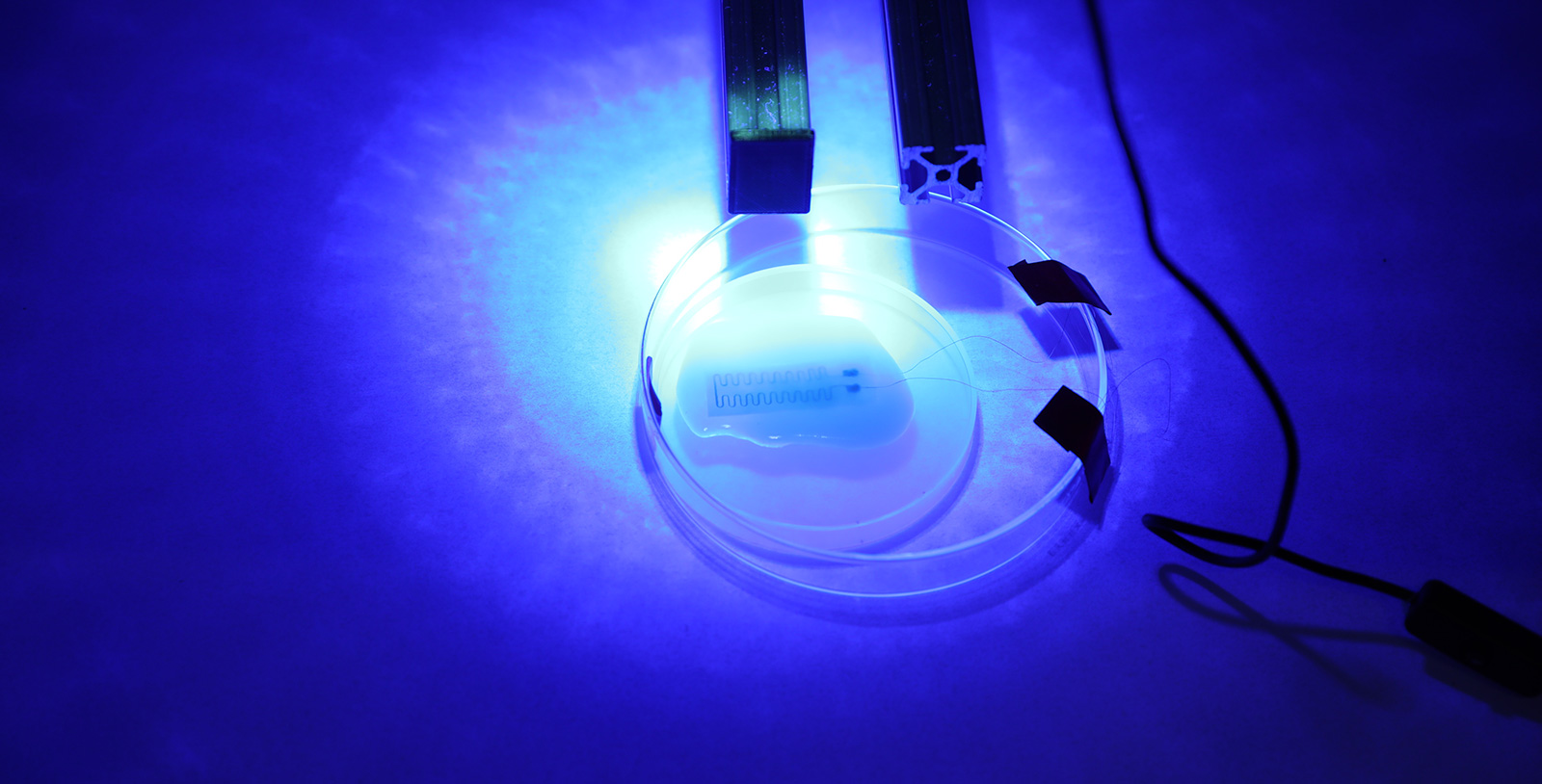
UV CURING / FINAL CROSS-LINKING
As a final step, to ensure that the fiber would not untwist, I coated it with a thin layer of PDMS, which took a day to cure as I could not put my twist setup in the small oven we have at the lab hence I had to cure it at room temperature. For this reason and to avoid introducing too much restriction to strain due to PDMS's higher young modulus, I coated the outermost layer using Ecoflex 30. After 2 layers of coating, I found that the pre-stored torsional energy was too strong that the fiber wanted to untwist, hence I added a bulky 3rd layer of Ecoflex 30 which made the sensor look ugly but in terms of functionality, it did the job. Finally I had a totally cured and secured, twisted microtubules filled with LM for both torsional and strain sensing.
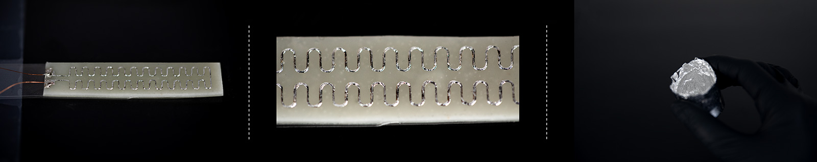
LCE-LM FILM ACTUATOR
And here's how two different width LCE films respond to 100°C as my heating gun unfortunately doesn't go below 100°C.
Learning Outcomes:
- I experienced many issues and failures during the fabrication process of the sensors as well while connecting sensors to the boards.
- While I was connecting my sensors to the board, I mistakenly pulled the header connector, which removed the pads entirely from the board. I needed to perform some micro surgery on the board with some jumper wires. However, i think i lost GND connection at some point and now the board has stopped being recognized by the computer. I will debug it and see where the issue is after the class.
Next Steps:
- Torsional sensors are cool and the LM-based one is very linear! Never thought about a use case for them but I will consider for further research in fiber based sensors.
- Inverse behaviour of the R in the knitted textile sensor using off the shelf resistive yarn deserves further investigation to confirm the hypothesis.
- LM-filled tubing was really easy to fabricate however when I replicated the capacitive sensor, I failed. Hence I need to better understand the parameters that matter for the capacitive sensor the authors from Dickey group produced.