INTRODUCTION

This week's assignment was twofold: (1) individual assignment: design, build, and connect wired or wireless node(s) with network or bus addresses, and (2) group assignment: send a message between two projects. This week I worked with a ESP32 with Wifi communication as I plan to use this MCU in my final project.
According to it’s Wikipedia page, ESP32 is a series of low-cost, low-power system on a chip microcontrollers with integrated Wi-Fi and dual-mode Bluetooth (Bluetooth and Bluetooth Low Energy). ESP32 is created and developed by Espressif Systems, a Shanghai-based Chinese company. It is a successor to the ESP8266 microcontroller. I refered to this tutorial page of FabLab Kamakura.
Barduino 2.0
Barduino 2.0 is a ESP32 based board which was designed by Eduardo Chamorro Martin with the help of Josep Marti and Oscar Gonzalez in FabLab Barcelona. I was given the parts and the board already cut for assembling it from my instructor. I soldered it firstly and then tried some sample code for checking its operation.
MILLING AND STUFFING
Parts
- ESP-WROOM-21 MCU
- 10K ohm resistor
- 100 ohm resistor (2x)
- Tact switch
- 3,3V 1A regualator
- red LED
- blue LED
- 10uF capacitor (2x)
- 1uF capacitor (2x)
- 6-pin header for FTDI
- ideally a slide switch (but since we were out of stock, I used a 3-pin header and a F-F jumper cable to simulate the slider
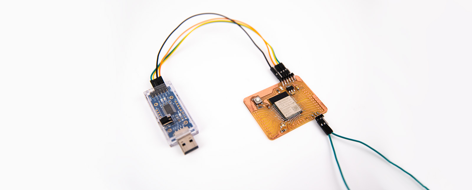
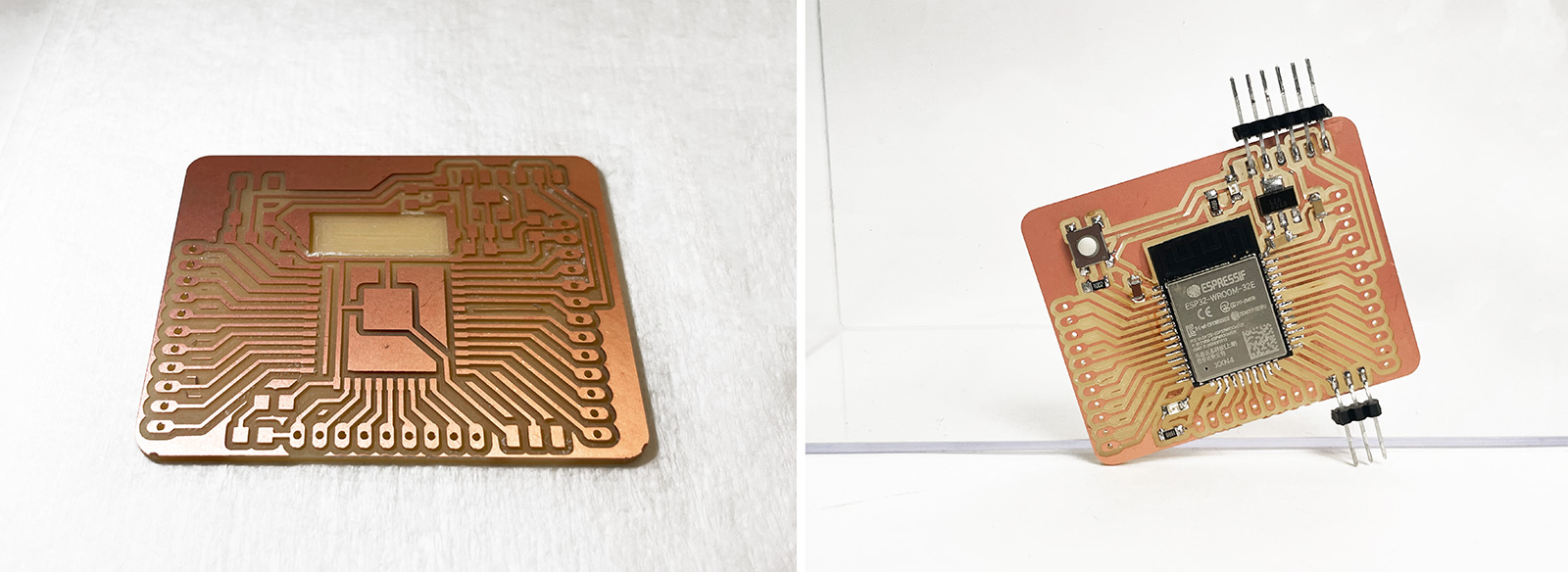
The soldering parts are very small on ESP32-WROOM. I applied flux onto ESP32-WROOM-32 not only the surface, but the side and all the bottom to cover the electrodes. For the first pin, I applied solder to the board first, and then soldered ESP32 onto it. For the headers, I used male pins instead of female pins. I soldered them on so I wire from the bottom of the board. FTDI cable is connected to the FTDI pins. The tact switch is for RESET, the slide switch is to change modes between Program and Run.
hello.ESP32-WROOM.echo
First, I tried to run hello.ESP32-WROOM.echo on Arduino IDE.
								// hello.ESP32-WROOM.echo.ino
								//
								// ESP32-WROOM echo hello-world
								//
								// Neil Gershenfeld 1/6/20
								//
								// This work may be reproduced, modified, distributed,
								// performed, and displayed for any purpose, but must
								// acknowledge this project. Copyright is retained and
								// must be preserved. The work is provided as is; no
								// warranty is provided, and users accept all liability.
								//

								void setup() {
								   Serial.begin(115200);
								   }

								#define max_buffer 25

								void loop() {
								   static char chr;
								   static char buffer[max_buffer] = {0};
								   static int index;
								   if (Serial.available()) {
								      chr = Serial.read();
								      Serial.print("hello.ESP32-WROOM.echo: you typed \"");
								      buffer[index++] = chr;
								      if (index == (max_buffer-1))
								         index = 0;
								      Serial.print(buffer);
								      Serial.println("\"");
								      }
								   }
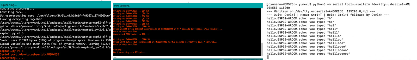
The procedure of writing program should always be: Switch to Program > upload the program using Arduino IDE > hit Reset button (timing doesn’t matter too much as long as it didn’t take too long after Arduino IDE says “connecting…”) The procedure for running a program is: Switch to Run > hit Reset button.
Blink
I opened example code for blink on Arduino IDE. Since my red LED is connected to pin 13 on this board, I added #define LED_BUILTIN 13 before void setup().
            							# define LED_BUILTIN 13

								void setup() {
								  // initialize digital pin LED_BUILTIN as an output.
								  pinMode(LED_BUILTIN, OUTPUT);
								}

								// the loop function runs over and over again forever
								void loop() {
								  digitalWrite(LED_BUILTIN, HIGH);   // turn the LED on (HIGH is the voltage level)
								  delay(1000);                       // wait for a second
								  digitalWrite(LED_BUILTIN, LOW);    // turn the LED off by making the voltage LOW
								  delay(1000);                       // wait for a second
								}
My LED didn't lit up at all although the board seemed to program without any issue. So the problem could only be around the LED or the LED itself as the hello world code worked without any issue. To debug, I first checked the connections in my circuit to make sure that the LED was getting any power at all. Once I confirmed that the traces were not the issue, it was either the resistor or the LED itself. I double checked my LED orientation as it's not the most obvious thing to get it right. My LED's orientation seemed correct, nevertheless I still replaced it. Then ran the code again but still no luck. Then I realized the faint blinking in the LED which was probably there all along but was barely visible. So I concluded that there wasn't enough power transmission to the LED hence I replaced my 100 ohm resistor. And voila, it started blinking!

ESP BLINK VIA BLYNK WIFI COMMUNICATION<
I tried using Blynk on my iPhone to control the board through Wifi communication. The most reliable resource for working this through was https://www.youtube.com/watch?v=IKbbvEzZ7wg
>
ESP32_WIFI
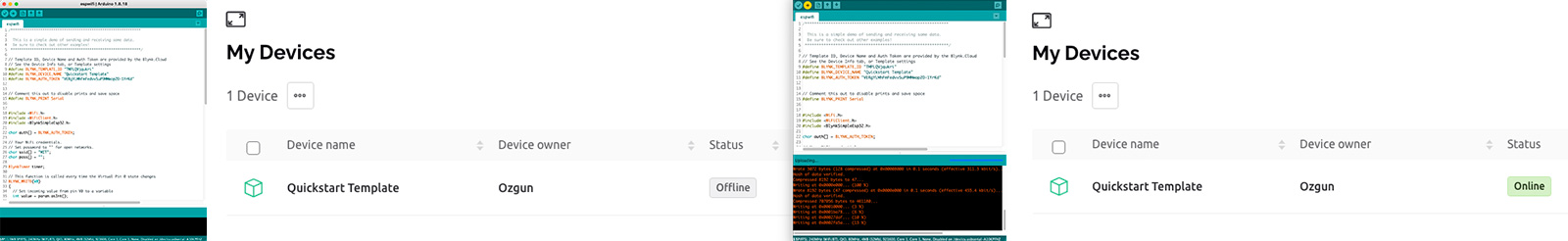
I followed the instructions on this page to install Blynk library on Arduino IDE. I opened Arduino IDE > Library manager through Sketch > Include Library > Manage Libraries. I searched for Blynk and installed the one coming to the top. And I opened the sketch through Arduino IDE > Files > Examples > Examples from Custom Libraries > Blynk > Boards_WiFi > ESP32_Wifi, and replaced “YourAuthToken” with my actual Token(the one sent to my email address from Blynk) , “YourNetworkName” with my Wifi SSID, “YourPassword” with my Wifi password.
EDGENT_ESP32
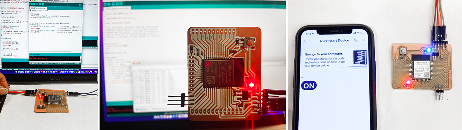
After writing the program, switing to Run mode, I was able to control the LED on my Barduino 2.0 through my phone!