INTRODUCTION: ZenBot

It was a train reck of a week. All of us in the CBA section had to build something together and succeeded. Now let's roll back to talk about the craziness of this week.
The ideas that came out of the brainstorming were:
- Sand castle building robot
- Knock Knock and other jokes robot
- Sand garden
- Latte art maker
…We all voted and it came to the sand garden. After some brainstorming. I volunteered to join the hardware team and our goal was to allow the user to draw on a canvas in the browser, take the drawing and convert to gcode, and send the gcode to the XY plotter.
WHAT I WORKED ON
I was on the machine hardware team so I did the following:
- built the full corexy stage from scratch based on Quentin's Urumbu Corexy
and this includes the following: - redesigned part of the machine elements such as adding a flexure to the bearing plates and changing the design of the capstan to fit more safely on the stepper shaft
- cut down the extrusions to size
- 3D printed all printable parts
- laser cut all laser cuttable parts
- did the machine threading and assembly
- re-built the z-axis attached to the end effector using a tiny linear rail and using a mini servo motor (for on/off magnetic field)
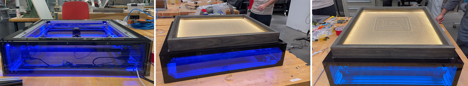
- finally built the RGB LED box lighting for the machine base to change the color of the machine
Laser cutting
I laser cut the files using 1/4" delrin and had to run the file 4 consecutive times (not 4 repeats cause in the repeat mode the laser goes over the same section 3 times which risks melting the material, however running the same print 4 times ensures that the parts get some rest before being exposed to the laser again). This was a critical finding to reduce the kerf. As for the settings, I used 0.8 speed, 100% power and 400ppi. The laser cut can be seen in the image below.
3D printing
Only a few parts were 3D printed and these were the capstan files. I realized that it was a perfect circular hole for the shaft while it should have either spots for microscrews to keep the shaft and capstan fully engaged, or the shape of the hollow part should have a flat face to interface the shaft properly and for them to move together while the stepper is working. So I edited this model to have a flat face and 3D printed it as seen in the image below.
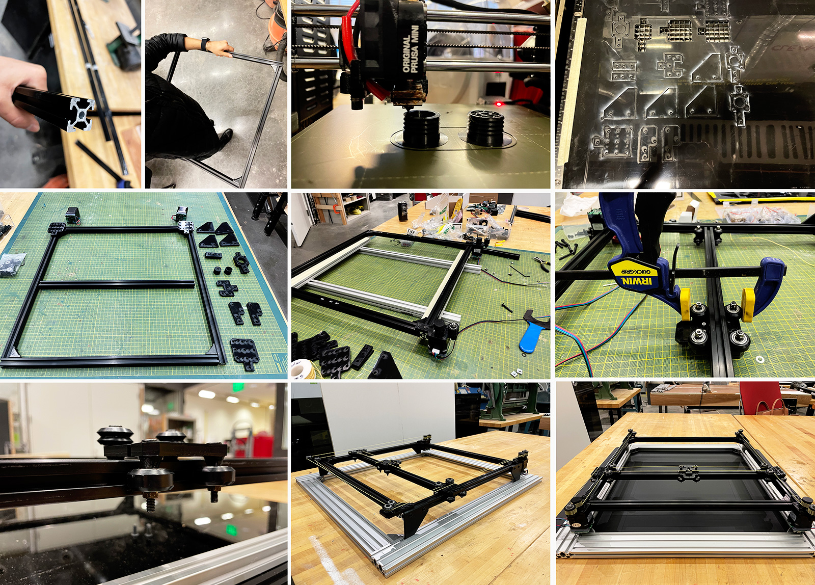
Assembly and Threading
Preparing the parts and assembly was quite straightforward however I faced a lot of issues in the alignment of the bearing plates. It was partially due to making the machine 150% larger than the original Urumbu corexy, but that wasn't all. The bearings somehow were not touching the slots of the extrusions and for this I had to replace the holes on the bearing plates 1 mm closer, as well as adding a flexure, as suggested by Quentin, to the plate. These two adjustments were gold and saved everything! See below the before and after movement of the stage!
Building the End effector Z axis
Leandra built the first version of the z-axis end effector however there were a few issues with smooth movement. I ended up cutting all the parts needed instead of printing as it was supposed to be rather thin pieces. Hence I ended up using delrin again, keeping the linear rail part same as before. Then did the assembly and it worked nice and smooth! Attaching a large permanent magnet in a stable way and avoiding drift during magnetic effect was a bit of a challenge but we resolved it nicely by making a more robust end effector assembly.
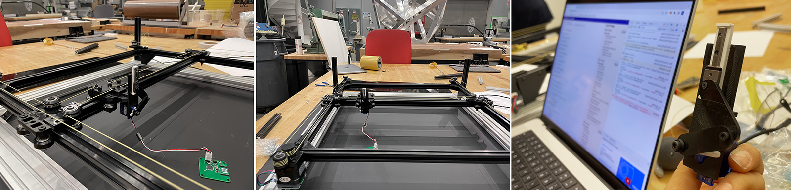
And here's a video of it being controlled!
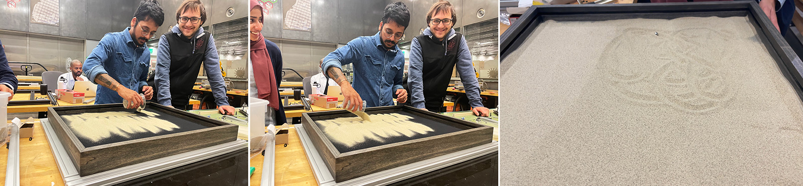
Pouring down the sand and calculating magnetic field distance
Finally Ishraki poured down the sand and we made some drawing tests by hand, holding the permanent magnet. The ball was rolling at a distance of 8mm to the base of the machine, and when we went further away to 1.5cm the contact was lost. Hence we set the end effector at a hight where it's displacement of 2cm was used most effectively to have regions of non contact and contact.
Testing integration
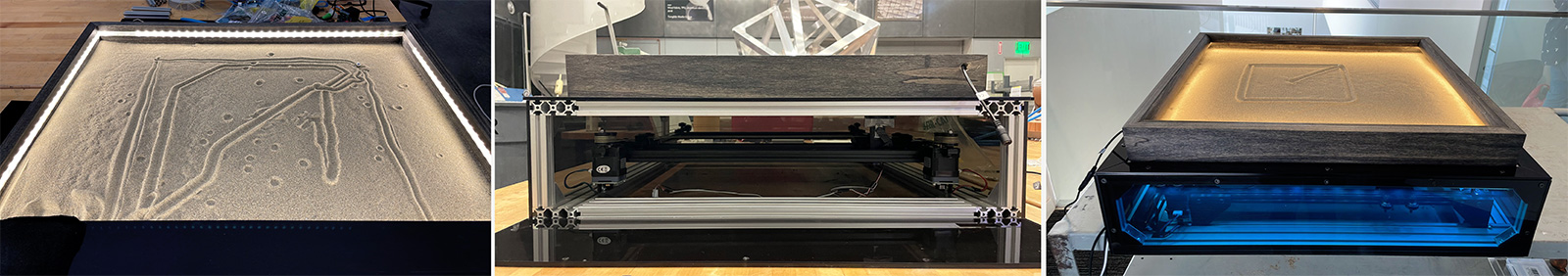
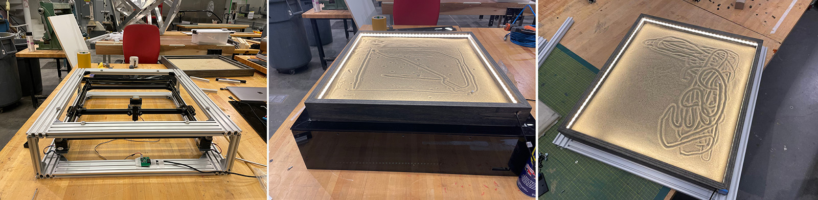
Together with Wenhao and Zihan, we worked on writing pre-defined matrices to finally test the fully assembled machine. At this point, the outer frames were built by Ishraki and I added stoppers on the legs of the machine to keep it stable on the base extrusions. Ishraki also built a top extrusion where we would safely place the sand stage. The machine was made modular so that we could explore the xy stage for other projects later as well!
Also I'm sobbing while documenting this and I'm probably doing a very incomplete documentation in relation to how much work and love has gone into making this machine, since I just learnt that our machine was accidentally trashed in the Media Lab loading dock. So as I'm writing this, the machine and 10+ people's week worth of labor and the parts provided to us by the staff has disappeared to thin air. So a worthy note, always store your projects in a safe place even if they are huge. The aftermath is otherwise very painful.
Demo - Drawing simple geometries with the sand
Finally I added the lighting to the base cause I love seeing and showing what goes inside the black box! Unfortunately, we could not successfully integrate the software team's work as there were incompatibilities between the data type prepared and what modular things received. Hence we had to copy paste the patterns each time it was generated and the motion was very scattered. So we needed to smoothen this motion further before demo day, however we couldn't complete it on time. But below is an instance of the machine drawing simple geometries and we are hoping to explore this further as it's a beautiful machine!