INTRODUCTION

This week was all about parametric design, computer aided design and computer controlled cutting. For laser cutting, I used Autodesk Fusion 360 for modeling, Adobe Illustrator for tweaking bits and bobs, and Corel draw for the final print of the cut file. For vinyl cutting, I did not use the vinyl cutter at the CBA shop since we had a lovely Cricut Cut Smart 2 in our lab (Tangible Media) that I wanted to further explore. I made sensor masks with it before and figured it could cut lines as thin as 100 micron, which I found super impressive for a hobby device! The below image is a summary of some outcomes from this week's how-to-make sessions: an actuated blooming flower and sensing kirigami.
1. LASER CUTTING
This week's laser cutting process consisted of two parts; (1) a group project for characterizing the machine and material of choice, and (2) and individual project where we build a parametric construction kit.
1.1 GROUP PROJECT
Characterizing the Machine: GCC
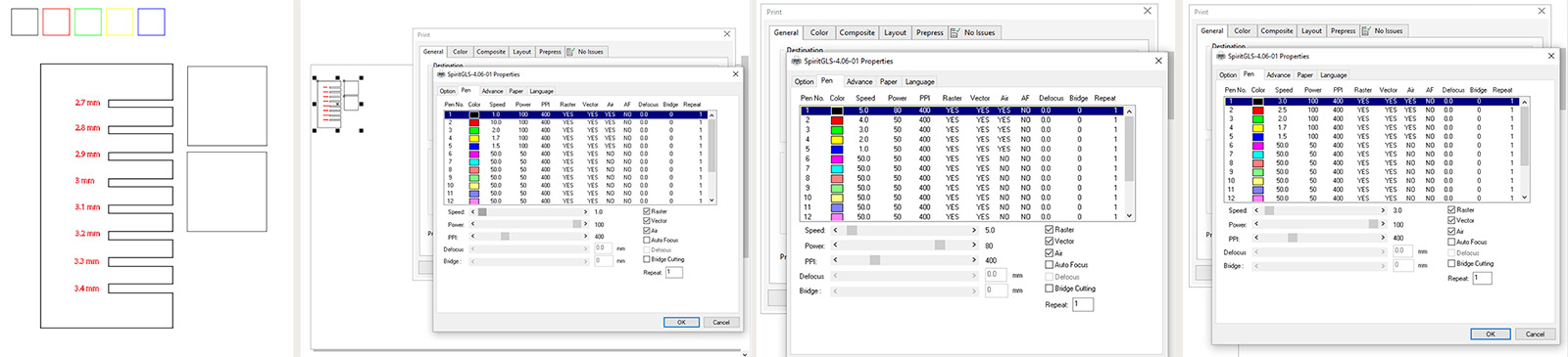
This week’s group assignment was to characterize our lasercutter's focus, power, speed, rate, kerf, joint clearance and joint types. This was necessary in order to calculate the kerf and proper dimensions for the joints we were planning to design.
Together with Wedyan, we printed 10x10 mm squares with the GCC laser cutter at the CBA shop, keeping power and PPI fixed to 100 and 400 respectively, and incremeting speed between 1 and 10. Our goal was to determine the optimal setting for cutting and rasterizing our acrylic sheet material of 3.05mm thickness. Through a total of 18 different variations of speed setting, we determined the most effective setting for cutting were 1mm/s at 100% power and 400 PPI for cutting, and at 100% power and 400 PPI at 10mm/s for engraving.
Understanding Material Behaviour: Acrylic
We chose to work with varying thicknesses (and colors) of acrylic sheet materials, that is 2.35mm, 2.6mm and 3.05mm. One major learning was that acrylic is definitely not forgiving, at least not as much as cardboard.
Advantages:
- It looks cool.
- You can utilize the transparency / translucency of the material as a design element.
- Cut pieces come out very clean.
- Can be cleaned very easily.
- Can fuse easily and robustly to another piece of acrylic.
Disdvantages:
- It cracks easily.
- There are thickness inconsistencies depending on manufacturing method.
- In thicker acrylics, living hinge is trickier to achieve (but also size and design dependent).
- Thinner acrylics tend to bend on laser bed and need to be stabilized before cutting.
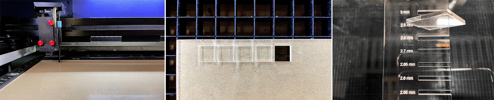
Calculating the Kerf
We designed a comb structure for varying kerf values starting from the material thickness and decreasing by increments of 0.1mm. The first results were that for an acrylic thickness of 3.05mm, 2.9mm cut size was somewhat loose and 2.8 was too tight. So we ran another test for smaller increments between 2.8 and 2.9mm. We found that 2.85mm gave us the best results for being able to robustly press fit the small squares in the cut section, but also able to remove it afterwards without using additional tools. Thus, we calculated the machine's kerf to be 0.20mm.
However, we found that the kerf is very dependent on the focusing. That is, when we cut the same file on the same material with the exact same print settings at different times throughout the week, we found that the kerf came closer to 0.3mm which, was quite a big difference. This resulted in having to rescale and remake some crucial parts in our designs.
Learning Outcomes
Given the change in calculated kerf across different cutting sessions, we came to the conclusion that it is best to cut your designs at once, if possible. We are still unclear on how the focus affects the kerf and this is yet to be investigated.
1.2 INDIVIDUAL PROJECT
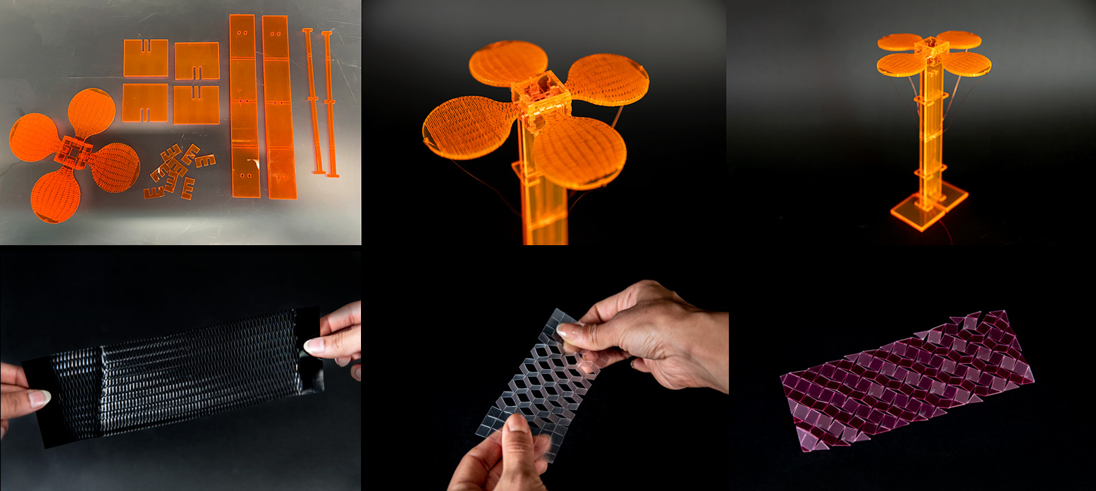
OmniFlower
This week’s individual assignment was to design, lasercut, and document a parametric construction kit, which can be assembled in multiple ways, and for extra credit include elements that aren't flat. While doing so, we needed to account for the lasercutter kerf.
Some old habits came back and I wanted to do a simple kinetic piece using my OmniFiber technology. OmniFibers are fluid-actuated fibers that can either be operated with compressed air or liquids. The idea I wanted to implement was one that my PI, Hiroshi Ishii, was asking me to do for a year! That is, making a blooming mechanical flower using the fibers as tendons that pull and release the petals. I started with a simple design and prototyped it, however there is a huge space for improvement as I couldn't do multiple iterations due to time and machine usage constraints. Hence, in this section I document the one and only iteration of the OmniFlower prototype, inspired by the aesthetics of the design below.

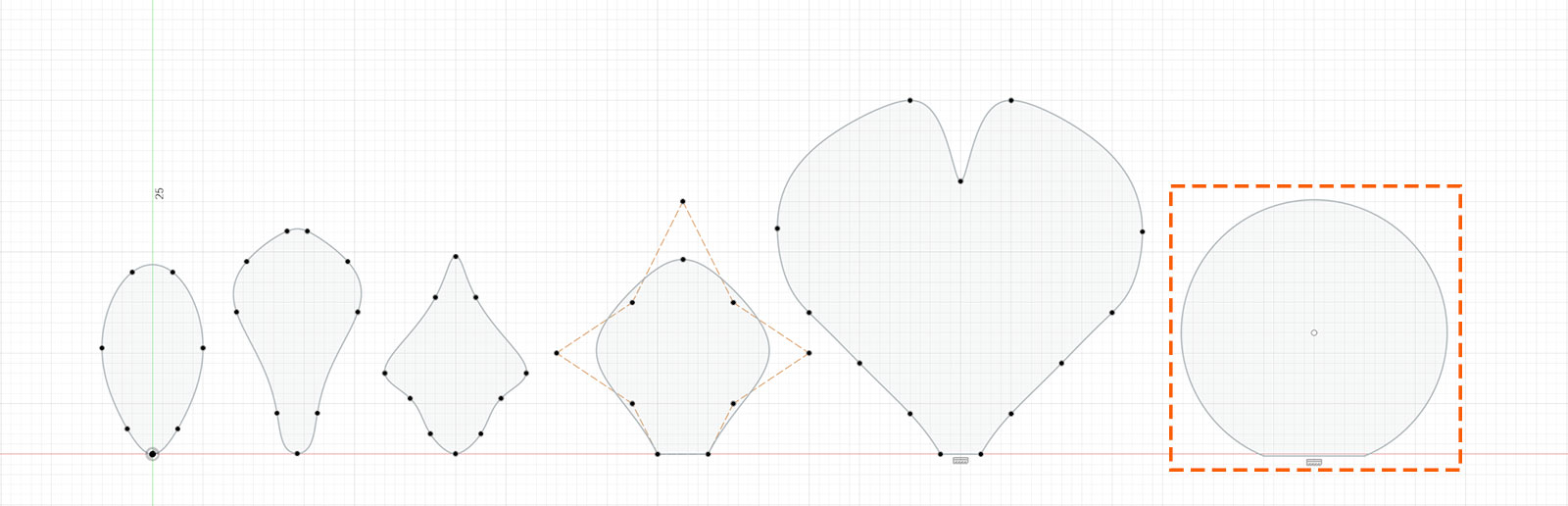
The Petal Design
First, I started by exploring some basic petal forms I could work with. I wanted them to be not too organic and neither too inorganic. After sketching several forms, I landed on a circular petal design for simplicity.
I also wanted to challenge myself to make a living hinge, a structure that I've admired for many years and never made so this was the opportunity! I chose the living hinge for it would allow the petals to move more organically. As Neil mentioned in the class, I could not find a design tool that would ease this process so I parameterized the cut lengths, the horizontal and vertical spacing between the cuts. This was particularly challenging to fit the living hinge design since I did not work with a polygon but rather a circular shape, but also where parametrization became very handy. I must admit, however, that some of the cut lines are ascribed a fixed length instead of a parameter, since I couldn't wrap my head around it.
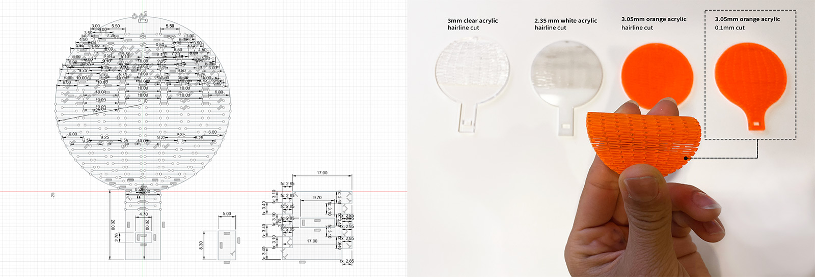
Multiple Joint Designs
Next step was finding a suitable joint for connecting the petals together, considering that they would be under some stress applied by the tendon. Recalling that wedge joint is both a forgiving and robust one, I decided to go with that. I made an initially simple design for connecting one petal to a flat structure with wedge joint. Afterwards, as I needed to connect all petals to one another, I used a second joint between each flat piece. Since I had a total of four petals in my design, I connected the flat pieces using double-side finger joints to one another. Together, they formed the rectangular middle piece connecting all four petals into a flower head.
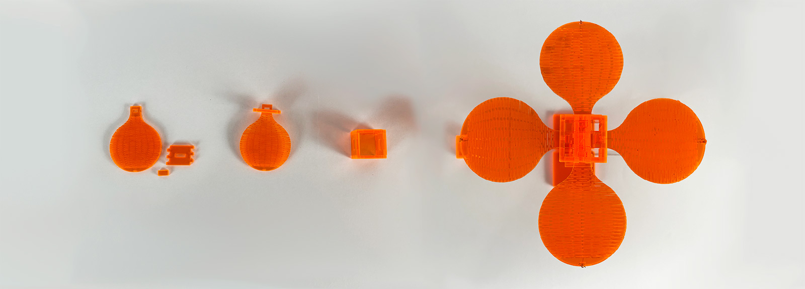
The final bit done on the laser cutter was the stem and the stand. It was done in an ad-hoc manner and I kept it rather simple using a set of press fitting parts for the following: (1) heightening the petal from the ground to be able to add tendons, (2) keeping the long 'stem' pieces stable, (3) keeping the global structure stable once actuated. Although I think I did fairly OK in the first two requirements, the overall stability needs to be further improved.
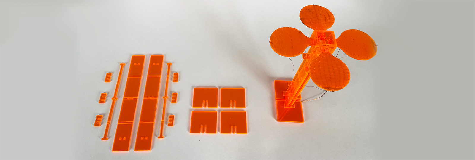
Final Prototype: OmniFlower
Finally, I added some wires to the petals and slid them through the core of the stem part. My initial aim was to control the petals separately for more expressive actuation, however 1) I did not have the time, 2) it didn't really make sense :) So, I winded the wires to make a single tendon structure, and connected them to an air-actuated fiber that contracts upon pressurization. The actuator is controlled by FlowIO device, a pneumatic development platform founded at the Media Lab (which I'm a co-founder of!)
It is controlled at 4 bars of air pressure, and since the flow rate is too high, I went with using a 2-meter-long fiber to be able to achieve slower actuation and also to refrain from using a flow regulator. Below, you can see a short video of the OmniFlower at work!
2. VINYL CUTTING
This summer when I was in Japan, I really grew fond of kirigami and its structural potential. In fact, the only thing I purchased and came back home with were a set of kirigami flower pots for decorative purposes. I have several of them on my office shelf as inspiration.
Immediately as we got the vinyl cutter training and CBA shop, I settled on using the vinly cutter for origami or kirigami structures; the first one for making creases and not cutting through the material, and the latter for making iterative cuts on the paper without losing off a considerable amount of material. First, I explored different kirigami structures and got lost in that world for a good three hours. Then, I came across several influential papers that characterize kirigami structures, one of which is Harvard SEAS Bertoldi Group's buckling-induced kirigami paper. Based on knowledge shared in this work, I started replicating some of the kirigami structures proposed in the paper. I further extended the work to test different thicknesses of sheet materials, different material properties, cut sizes, hinge dimensions and angles; all of which generated about 10 unique samples. I further explored using kirigami to make a simple a resistive sensor. This was my favorite part of this week as it allowed me to do a deep dive into a world which I was fascinated by, the world of kirigami.
1.1 KIRIGAMI GEOMETRIES
(ˌkɪrɪˈɡɑːmɪ ) noun. the art, originally Japanese, of folding and cutting paper into decorative shapes.
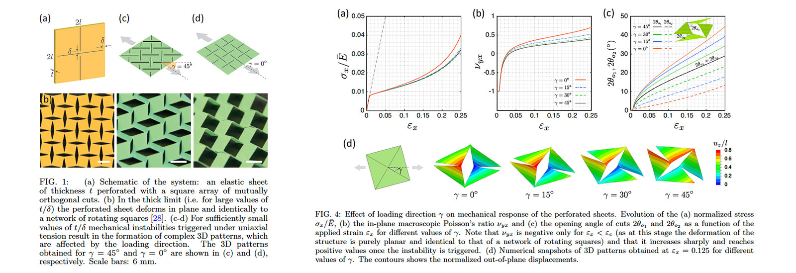
Recently, kirigami—the Japanese art of paper cutting—has been identified as a powerful tool to realize programmable mechanical metamaterials. A key feature of kirigami metamaterials is that they are conveniently cut when flat and then exploit local elastic instabilities to transform into complex 3D configurations upon stretching. According to An et al.'s Programmable Kirigami paper, most of the previous studies on hierarchical kirigami metamaterials have considered thick sheets and focused on their in-plane deformation. That is, the out-of-plane buckling behavior of thin hierarchical kirigami sheets remains largely unexplored. Hence, they investigate in detail both the effect of geometry as well as plasticity of the sheets.
Following this work, and based on the figure below from the paper, I investigated the tensile response of elastic sheets of thickness t perforated with: (1 ) a linear array, and (2) a square array of mutually orthogonal cuts. I further introduced variations in cut geometry (e.g. wavy lines), the cut-hinge angle, while the thickness is progressively increased/decreased.
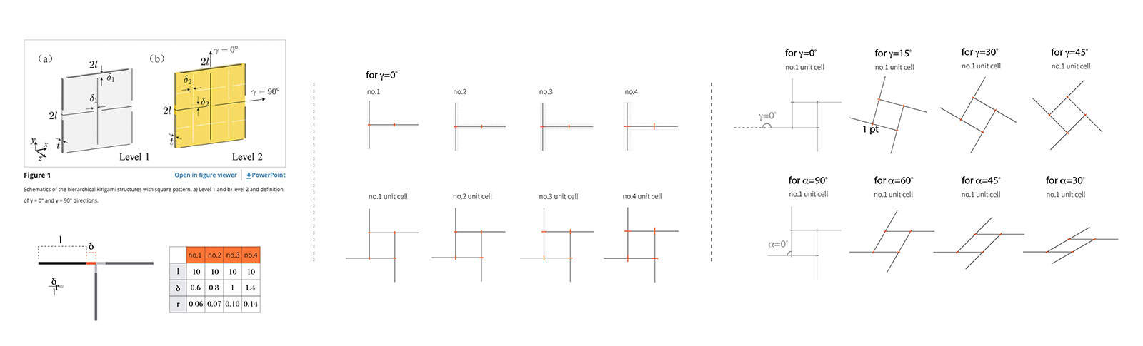
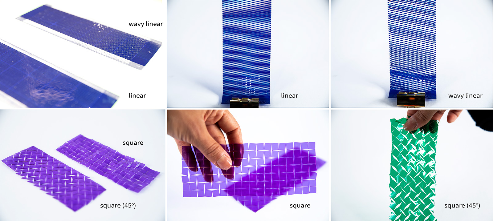
The patterns I explored are as follows: (1) linear, (2) wavy linear, (3) square, (4) 45 degree square, (5) 60 degree shear. Among these, the linear and wavy linear did not demonstrate a trivial mechanical (and later resistive) variation. Whereas the square and 45 degree rotated square pattern resulted in different buckling behaviour. A further observation was that the linear cut patterns were much less prone to buckling given that the material used is sufficiently thin.
1.2 KIRIGAMI SHEET MATERIALS
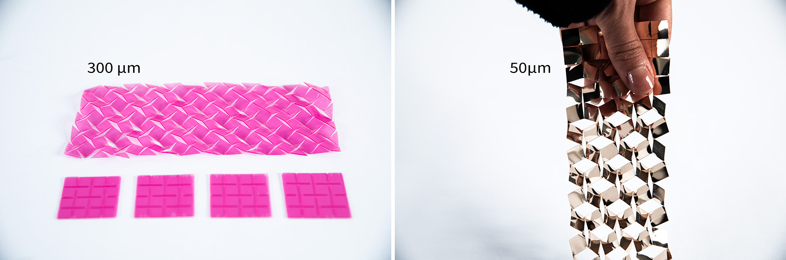
From tests with large variance in thicknesses of materials, it was obvious how the thickness affected buckling behaviour. In the below image, we use a thin plastic film of 50 micron, and a 300 micron sheet, where the elastic return of the 50 micron film is near 100% while the 300 micron sheet has near 0 return to the initial shape without external stress.
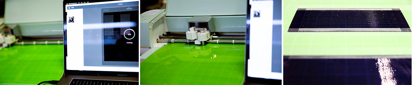
1.3 KIRIGAMI ON CRICUT
The process of cutting with Cricut Smart 2 was fairly straightforward. You need to export your files in .svg format as all other formats (png, dxf, dwg, pdf) resulted in various conversion issues. Once the .svg file is uploaded, the rest of the process is as follows: (1) upload to canvas, (2) choose material thickness, (3) make it! While designing the kirigami pattern, we took into consideration that the smallest detail that would hold its shape integrity is around 100 microns with the cricut machines. That being said, this is also material-dependent e.g. it would be much harder with cutting knitted or woven fabrics than other non-woven sheet materials like paper or plastic films.
1.4 SENSING KIRIGAMI
Finally, inspired by Sensing Kirigami paper I cut a set of electrically conductive carbon doped papers purchased from McMaster Carr and Pasco. The carbon-filled UHMW polyethelene film from McMaster was 0.005", and the Pasco carbon-filled paper is ~350 microns thick. Further, the polyethelene film had a much slippery surface than the Pasco paper sheet. The paper sheet had more surface texture and was prone to easily getting damaged or scraped off which resulted in immediate change in resistivity. We cut both linear and square patterns, and their variations, with both papers. The resulting behaviour in respect to material thickness was as expected; the thinner kirigami had higher elastic return (~85%) and the thicker one demonstrated buckling once stretched.
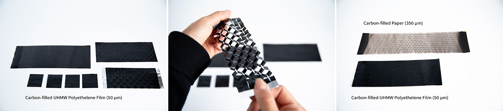
Since the thicker carbon-filled paper had no elastic return and was more prone to damage but the Cricut knife, I only cut and characterized the resistance range of the UHMW polyethelene film for the final sensor samples. Due to the pattern, the thin cut linear pattern had higher initial resistance after being cut, that is ~90 Kohms, while the square cut pattern had larger cells and thus lower initial resistance of ~16,5 Kohms. Upon 80% strain, the linear cut pattern resulted in a resistance change of 0.4 Kohms, while the square cut pattern increased resistance by 0.8Kohm and was more sensitive to minute strains than the linear cut pattern, as can be seen in the video below.
To share some final sentiments: I've absolutely fallen in love with the potential of using kirigami for sensing architectures, but further, I am tempted to and most likely will keep on investigating their use as sensors and actuators made from stimuli responsive polymeric materials such as shape memory polymers and elastomers, dielectric elastomers and as reinforcement for hydraulic actuators such as OmniFiber!