INTRODUCTION

This week's assignment was to make something big using the ShopBot CNC router machine. Given my background, I am pretty comfortable working with machines that make small things (nano/micro) range but not machines that make big objects. Since it was my first time working with a large CNC machine, and the heads-up we had Neils gave us about how critical time will be this week, I decided to build something absolutely mesmerizing (as concept) I've been meaning to build for a while - that is A BOX KITE!
We got training by Tom and John on how to use the ShopBot CNC router as well as on how to use the V-Crave software to generate the toolpath the machine will follow to make the cuts! Also it goes without saying that TA David was a super-star this whole week helping us with both toolpath generation and machine operation until late hours - thanks again David! You are a lifesaver.
MAKE SOMETHING BIG!
1.1 Box Kite Design
A simple method of constructing a box kite is given in detail as follows: The sticks should be made of straight-grained wood, which may be either spruce, basswood, or white pine. The longitudinal corner spines, A A, should be 3/8 in. square by 42 in. long, and the four diagonal struts, B, should be 1/4 in. by 1/2 in., and about 26 in. long. Two cloth bands should be made to the exact dimensions given in the sketch and fastened to the four longitudinal sticks with 1 oz. tacks. It is well to mark the positions of the sticks on the cloth bands, either with a soft lead-pencil or crayon, in order to have the four sides of each band exactly equal. The ends of the bands should be lapped over at least 1/2 in. and sewed double to give extra strength, and the edges should be carefully hemmed, making the width, when finished, exactly 12 in.
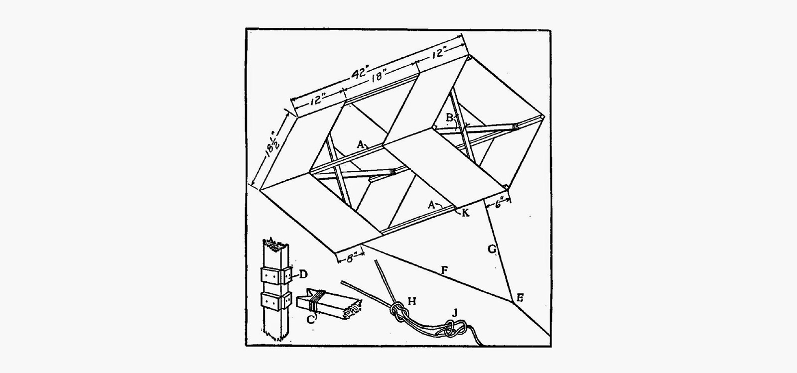
Probably the best cloth for this purpose is nainsook, although lonsdale cambric or lightweight percaline will answer nearly as well. The diagonal struts, B, should be cut a little too long, so that they will be slightly bowed when put in position, thus holding the cloth out taut and flat. They should be tied together at the points of intersection and the ends should be wound with coarse harness maker's thread, as shown at C, to prevent splitting. The small guards, D, are nailed or glued to the longitudinal sticks to prevent the struts slipping out of position. Of course the ends of the struts could be fastened to the longitudinal strips if desired, but if made as described the kite may be readily taken apart and rolled up for convenience in carrying.
The bridle knots, E, are shown in detail at H and J. H is a square knot, which may be easily loosened and shifted to a different position on the bridle, thus adjusting the lengths of F and G. A bowline knot should be tied at J, as shown, to prevent slipping. If the kite is used in a light wind, loosen the square knot and shift nearer to G, thus shortening G and lengthening F, and if a strong wind is blowing, shift toward F, thereby lengthening G and making F shorter. In a very strong wind do not use the bridle, but fasten a string securely to the stick at K.
3D Printed Box Kite
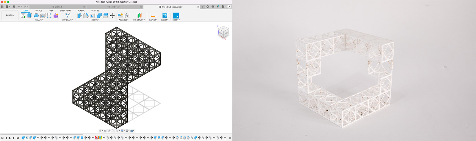
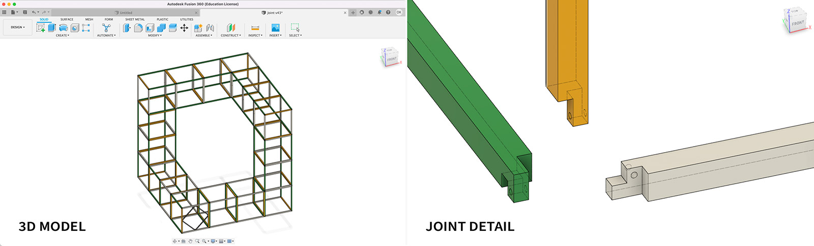
First, I designed a 3D printable version of the box kite structure to get an idea of the 3D shape and also to have SOMETHING SMALL alongside the large scale kite. This version does not include any of the joints but just a simplified version of the kite skeleton. Once the prints came out and I decided on the beam thickness / beam length ratio, I started designing my final kite skeleton in Autodesk Fusion 360.
Corner Joinery
Since the structure is supposed to fly, it needs to be lightweight hence I did not wish to add any additional joint structures but use the beams themselves to create the joint. For this reason, I did some research on 3-way corner joints for wood joinery. Of course, I also had to consider the CNC's affordances that we used this week, which allows for less 3D structures and more 2D cuts (+pockets). Hence, this reduced the number of options and I chose the joinery technique where the 3 parts press fit as in the image below.
1.2 OSB on ShopBot
Due to using 1/4" tool, I had to scale my initial design to almost 2.5x and ended up having massive single modules made of 90cm beams. Although I knew that this would make the final structure super heavy as we almost used the whole of a 48"x96" OSB sheet to only make 4 of the 18 modules, I still wanted to do the requirements of the week and fabricated the beams using OSB on the ShopBot. Also John insisted that I should make it HUGE since the fun of the week is making things massive. But, this was way too big for me hence I did not pursue finalizing the structure but just learnt how to generate toolpaths, operate the machine and observe the cutting process.

1.3 Delrin and Acrylic on CO2 Laser Cutter & Plywood on ShopBot
Step 1: Laser Cutting
Since my parts required being thin for a lightweight structure and not being able to manufacture this on shopbot machine, I ended up having parts of my kite made on the GCC laser cutter.
The first step was to characterize the laser cutter to make pockets on the faces so I could easily assembly parts without any issue. I referred to the kerf we determined in week 2, however I had to additionally characterize the depth of the pocket I needed by playing around with the speed for engraving the surface of the beams to be able to sacrifice half thickness of the material. Hence, I started with a fairly large speed values, since we achieved a not too deep engraving with speed 10 in week 2's group work, so I thought this would be a good start. I attributed different color codes to the following speed values; 7, 6, 5, 4, 3 and 2. The results showed that to be able to make a pocket at 1/2 depth of the beam, my speed value had to lie somewhere between 2 and 3, and closer to 2. I did a second test with color coding the following values; 2.7, 2.6, 2.5, 2.4, 2.3 and 2,2. The results came out as 2.4 and 2.3 may both work but to be on the safe side so that my joints work well without causing too much weakness in the pocket part, I went ahead with a speed value of 2.3. I did a test for the joinery for 3 beams as this would give me a clear idea if the joints would work all the way through the structure. I succeeded to make a nice joinery without using any glue! Hence I designed the final file with a total of 216 beams which would take roughly 6 hours machine time to cut and engrave, with the engraving part being the most time consuming part. So I started the job and moved onto finalizing my design for the connector diamond parts to introduce stability to the thin beam structures.
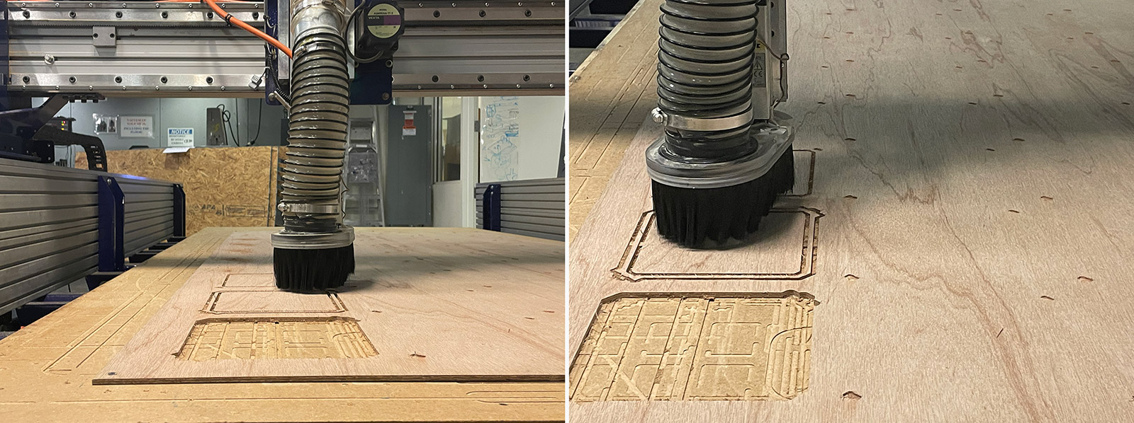
Step 2: Shopbot
With David's heroic help, I successfully generated the toolpathing for my diamond parts to be cut from very lightweight balsa wood. I was aware that cutting out the diamonds in single piece would introduce a lot of leftover material and not a good use of the sheet wood, but otherwise there was almost no way I could introduce the stability I wanted, as well as taking way too much time for the cut, if I had divided the diamond geometry into multiple pieces for space saving and responsible use of the material. But it was a bit of a cringe while cutting nevertheless and seeing a lot of wasted material :) I will definitely improve this design in the next round.
Once creating the toolpath, David also helped me kickstarting the cutting process on Shopbot as I wasn't entirely comfortable operating the machine on my own. Thankfully, the job didn't take too long and I had good looking diamond structures cut out from my sheet wood. However, due to the large endmill we used combined with the structural alignment of the wood, I had a lot of chips hanging from the side of the wooden pieces that would need to be sanded off to achieve clean edges. The sanding process took about an hour and a half to finish all 24 pieces.
Step 3: Assembly
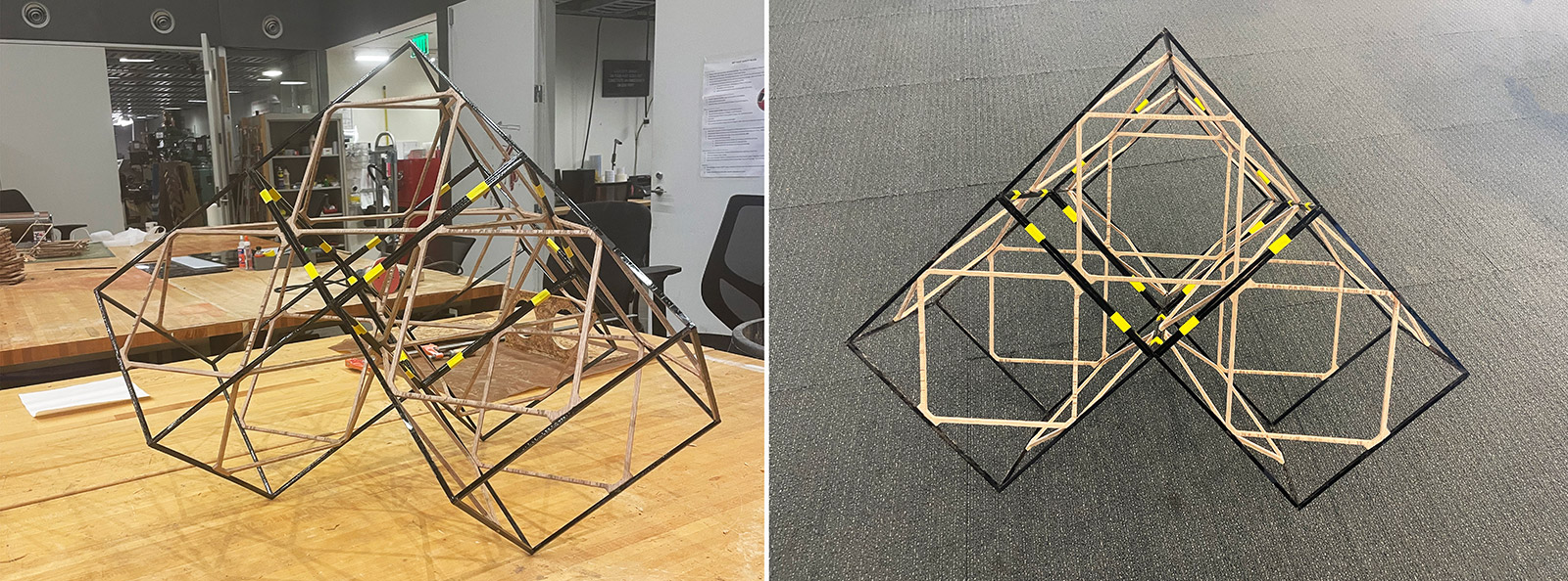
Once the parts on the laser cutter were finished cutting, I started putting things together. First I created an open cube structure as I had to place the diamond elements before finalizing the cubic modules due to the press fit joinery. So I made the open cube without the toop, fitted the diamonds in place on each face, and then finalized with adding the top beams. I had a neat looking cubic module! Now I had to do this for 17 more times for a total of 18 modules that would make the complete box kite! I was proud that i did not have to use any glue, however due to time limitations and a bit of poor design, I combined each cubic module using a strong yellow tape on each intersecting beam across two modules.
HOW TO MAKE SOMETHING SMALL AND BIG
Thankfully, before diving into making the full scale structure, I tested the box kite in small scale by 3D printing on Prusa MK3S.
2.1 Scaled Down 3D Prints
This was a model study as preparation for the final structure's look which came out pretty successfuly without using any support except for one part that had an overhang of 10cm. Otherwise, the rest of the structure was unsupported and came out perfectly fine. As I was quite sure that I wouldn't be able to complete the full kite structure, it was a good to have to bring to the class to demonstrate what the final structure would look like.
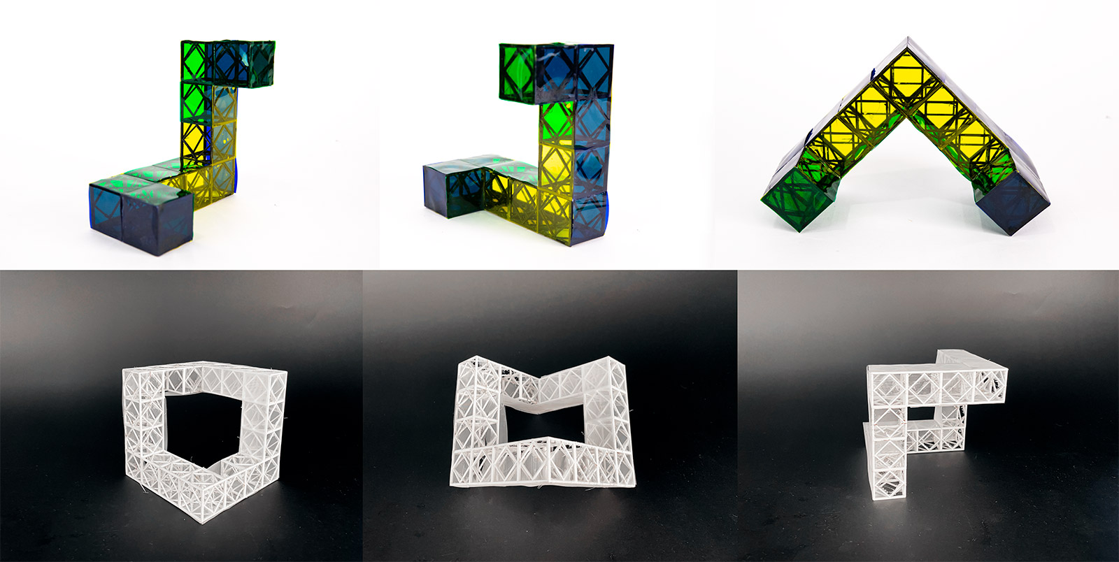
2.2 Laser + CNC-cut Final Design (partially implemented)
Below is the final status of the box kite with only 4 modules I was able to complete. I was pretty happy with how things turned out despite the material and cutting parameters drama I had throughout the week, since my materials arrived way too late and some of the materials (HDPE) I ordered, I was not allowed to cut on the GCC due to potentially harmful fumes, and learning way too late in the process that we could only use the quarter inch tool for the shopbot this week. I belive this was still a success given these facts, and I am determined to redesign and make the kite from carbon fiber for an actually lightweight structure. I hope to be able to fly the kite at the final presentation week! Imagine how cool it would be to see something big I made high in the sky!