INTRODUCTION

This week was all about designing a mold around the stock and tooling that we'll be using, mill it (rough cut + three-axis finish cut, and use it to cast parts. I wanted to take advantage of the potential for the assignment to allow me to work towards my obvious interest in soft, stretchable sensor and actuators. We decided to join forces this week together with Wedyan and did a truly collaborative soft robotics project.
We based our design on this recently published paper on a novel type of pleated pneumatic artificial muscle. A team of researchers at Istituto Italiano di Tecnologia's Bioinspired Soft Robotics Laboratory has developed a new pleat-based soft robotic actuator that can be used in a variety of sizes, down to just 1 centimeter. In their paper published in the journal Science Robotics, the group describes the technology behind their new actuator and how well it worked when they tested it under varied circumstances.
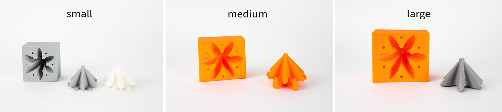
The researchers 3D printed their actuators, which allowed a wide variety of sizes. They have named the results GeometRy-based Actuators that Contract and Elongate (GRACE). The GRACEs consist of a single-material pleated membrane and do not need any strain-limiting elements. They can contract and extend by design, as described by a mathematical model, and can be realized at different dimensional scales and with different materials and mechanical performances, enabling a wide range of lifelike movements.
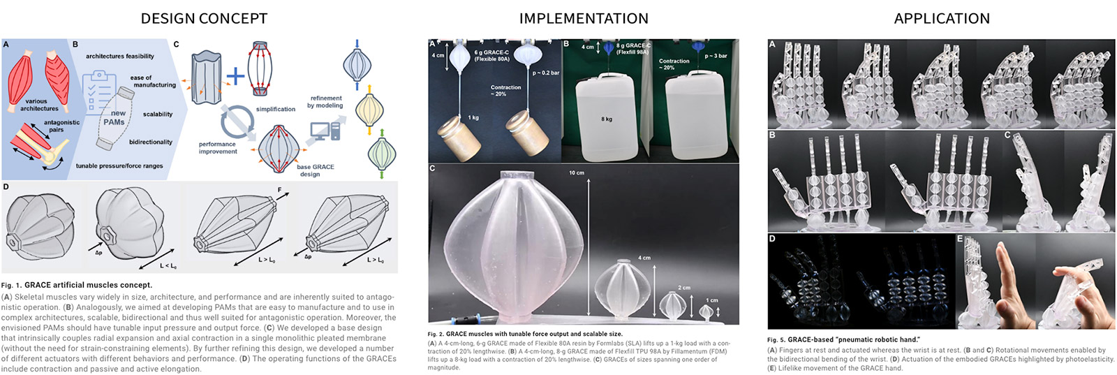
Additive manufacturing methods for elastomers today still remain either challenging or expensive, and therefore we decided to take another fabrication approach to make GRACEs using molding and casting. This method is especially useful for making modular constructs as the mold allows casting the same structure over and over. This week's assignment made a great excuse to replicate this work, and augment it with resistive sensing elements for making proprioceptive actuators.
1. 3D Modeling and 3D Printing the Mold
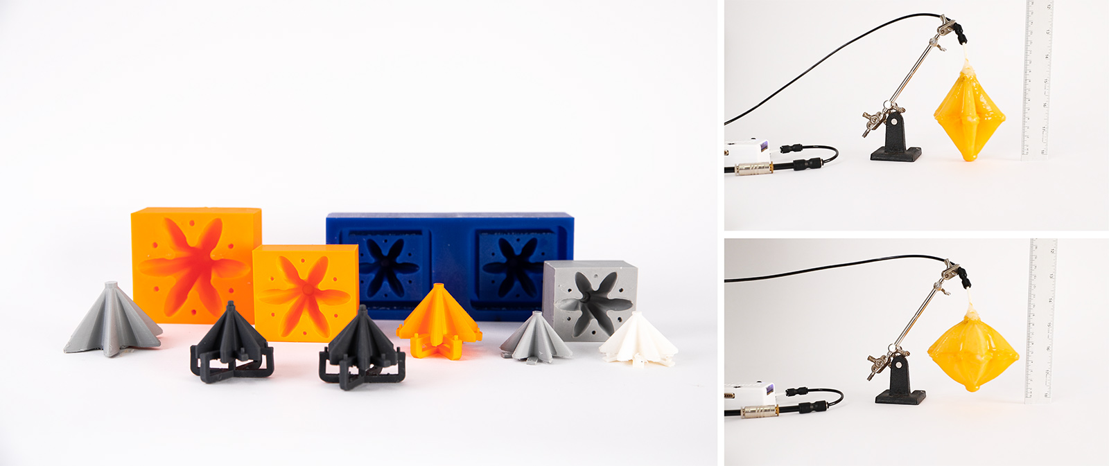
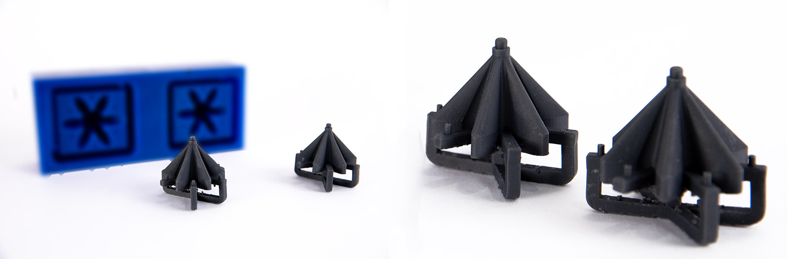
For testing that the actuator would in fact work as desired, before milling our wax block we decided to 3D print the mold. This was especially crucial since we had limited wax block size and availability, so we had to initially make sure that the design would in fact work. Working with fiber reinforced PAMs in my past work, it was not immediately intuitive to think about this class of PAMs working behaviour where the core concept builds on the varying wall thickness and pleat geometry rather than reinforcement with an additional mnaterial. THis was both a great challenge and a risk to take as it could have resulted in a massive failure. (Spoiler: But it did not!
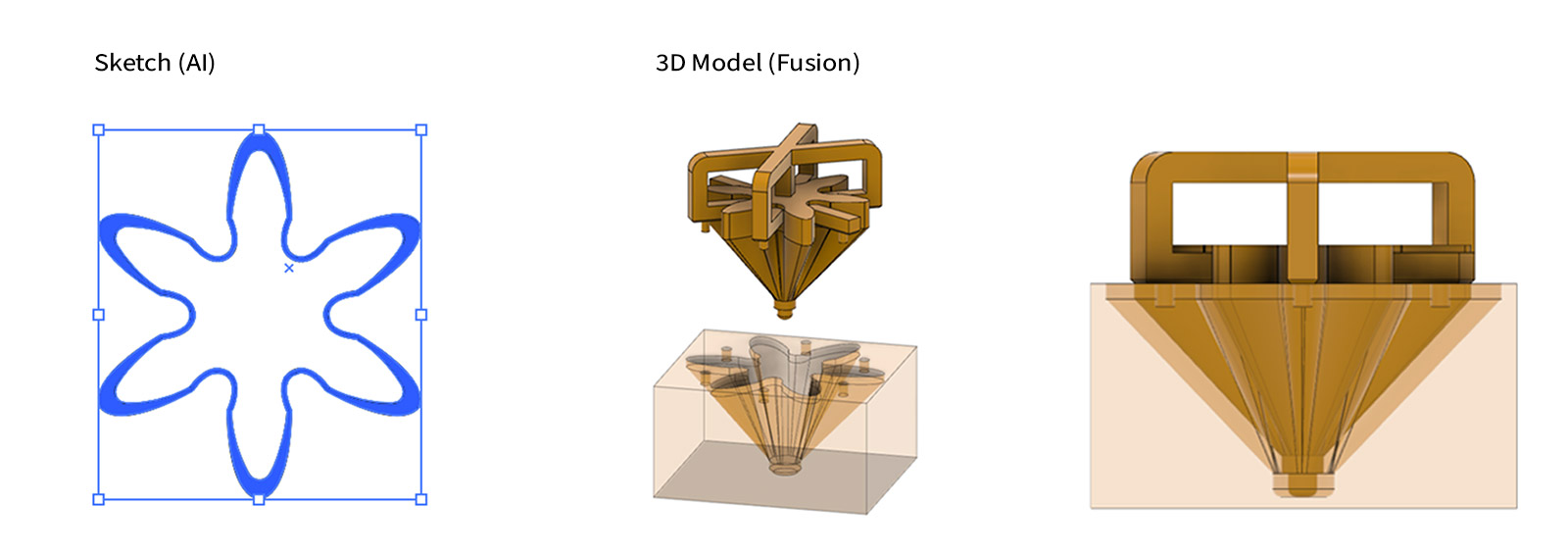
For generating the CAD design, we used Adobe illustrator for the initial 2D sketch (left image) and fusion 360 to render the 3D model. Following the 2D sketch, Fusion 360 was used to generate the extruded 3D model. Since we are directly milling our negative mold, as seen below, our model consists of two parts. One is the bottom part which will form the outer structure of GRACE. The second is the top part which will form the inner structure of GRACE, ensuring that it will be a hollow shell.
As shown in the left photo below, we started with the 2D sketches provided on the referenced paper as a starting point. It is worth mentioning that the paper explored multiple geometries and dimentions; we decided to go with the one that they mentioned performed better in contraction. This structure has narrow ellipses and deep pleats, which can largely expand when the GRACE is inflated. On the right, the isometric and side view of the 2-part mold is shown.
1.1 FDM PRINTING ON PRUSA MK3S+
TWO-PART MOLD: EXTERNAL AND INTERNAL LAYERS
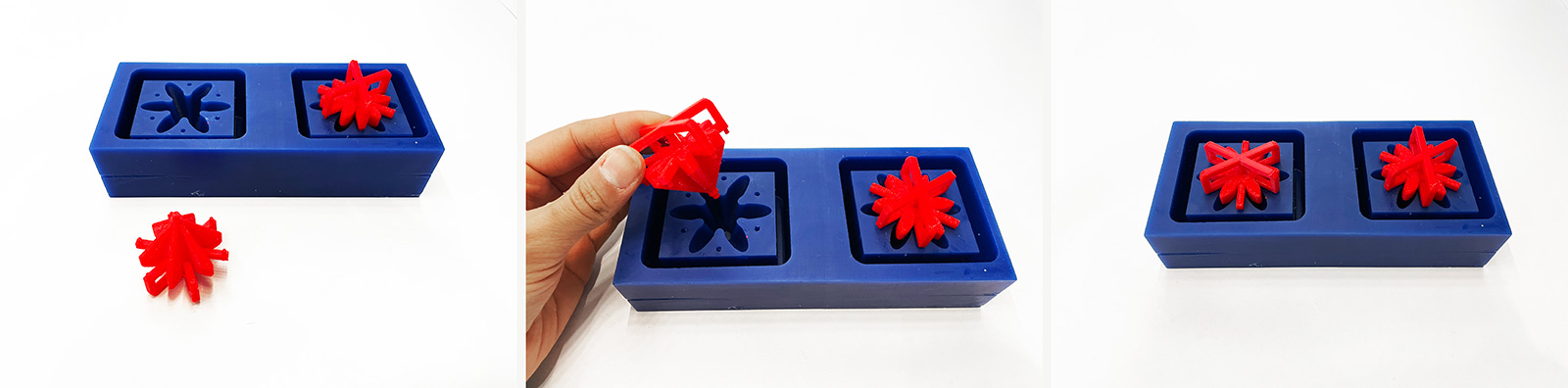
To test that our actuator would work, we printed the two part mold on Prusa MK3S and iterated on the design 4 times to be able to get the top part easily out of the bottom mold. A few times, the holders of the top mold cracked so we changed the print parameters to print with 100% infill for the top part while the botton part of the mold had thick enough walls to be strudy enough without any structural deformation (e.g. bending, warping).
RIGID EXTERNAL + FLEXIBLE INTERNAL LAYER
We designed a comb structure for varying kerf values starting from the material thickness and decreasing by increments of 0.1mm. The first results were that for an acrylic thickness of 3.05mm, 2.9mm cut size was somewhat loose and 2.8 was too tight. So we ran another test for smaller increments between 2.8 and 2.9mm. We found that 2.85mm gave us the best results for being able to robustly press fit the small squares in the cut section, but also able to remove it afterwards without using additional tools. Thus, we calculated the machine's kerf to be 0.20mm.
1.2 SLA PRINTING ON FORMLABS 3
TWO-PART MOLD: OUTER AND INNER LAYERS
This week’s group assignment was to characterize our lasercutter's focus, power, speed, rate, kerf, joint clearance and joint types. This was necessary in order to calculate the kerf and proper dimensions for the joints we were planning to design.
FLEXIBLE INTERNAL LAYER
Together with Wedyan, we printed 10x10 mm squares with the Beam Dynamics LMC10000 laser cutter, keeping power and PPI fixed to 100 and 400 respectively, and incremeting speed between 1 and 10. Our goal was to determine the optimal setting for cutting and rasterizing our acrylic sheet material of 3.05mm thickness. Through a total of 18 different variations of speed setting, we determined the most effective setting for cutting were 1mm/s at 100% power and 400 PPI for cutting, and at 100% power and 400 PPI at 10mm/s for engraving.
Advantages:
- Pieces come out very clean.
- Surface finish is much smoother than FDM printed parts.
- Easier to remove supports.
Disdvantages:
- Small details are fragile, especially during removal of the mold.
- Resin inhibits the curing of innermost silicone layers;
2. Materials and Pouring into the Mold
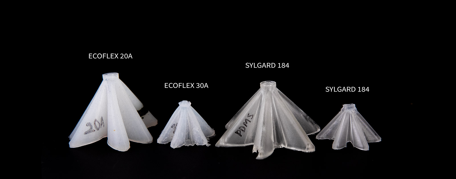
We tried to cast a variety of materials, including PDMS, Smooth-On EcoFlex 20A), 30A and 50A. We used Smooth-On SIL-poxy rubber silicone adhesive to bond the two casted parts together.
2.1 ECOFLEX SERIES
ECOFLEX-20A
We used a rapid cure ecoflex 20A (2 hours at room temp, 20 minutes at 60 degrees celcius in the oven) as we had a brand new silicone we purcased. It seemed to work fine but in larger pieces with thin walls, the silicone shape was not able to hold its structural integrity, hence we elimitaed this material easily.
ECOFLEX-30A
I had some ecoflex 30A (4 hours of curing time at room temp, 30-35 mins at 60 degree celcius in the oven) which we tested after we weren't happy with 20A results. The integrity improved however the material was still too soft for our purposes to keep the nice pleated form.
ECOFLEX-50A
Due to 20A and 30A not providing satisfactory results in structural integrity of the pleated form, we increased the durometer to 50A. Since the only 50A we had at the lab was from 2018, we tested the shape with this very much outdated material. It worked to an extent, but the pieces got easily ruptured. Due to this limitation, we went back to using 30A for the final fabrication.
2.2 PDMS: SYLGARD 184
We had a brand new Sylgard 184 at our lab, so we also wanted to give PDMS a chance however keeping in mind that it might be too rigid and might require higher working pressures. However I had high expectations from structural integrity, also the clarity of the material which would be beneficial to see embedded sensor channels. Although the curing time took much longer, we found a temperature that we could set in the oven for faster curing, witout sacrificing the wax base mold. In our first test, we tried to cure at 80 degree celcius in the oven which started melting the wax (we could see fumes) and upon double checking the wax material's properties, we figured that 60 degrees should be safe enough. Hence we reset the oven temperature to 60 degrees and everything worked without any issue with a neat looking actuator.
Learning Outcomes
NEVER EVER USE MATERIALS THAT HAVE EXPIRED SHELF LIFE (EVEN IF THEY'VE NEVER BEEN OPENED!)
3. 3-AXIS MILLING ON SHOPBOT
3.1 PREPARING THE TOOLPATH
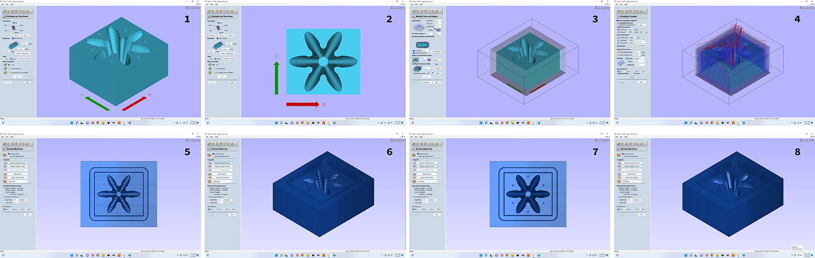
In order to generate the tool path for 3-axis milling, we used Vectric 3D cut software.
Following the guide provided by John and Tom from CBA , we were able to generate the tool path file that the 3-axis milling machine will read. Given the time and material limitation we had, we decided to mill the bottom part of the mold, and 3d print the top part of the mold to be inserted. We loaded an STL into the software. We used a .125” ball end mill since it would be more suitable for carving the curved valleys in our model. Our stepovers were 40% of the tool diameter for the roughing toolpath and 10% for the finishing toolpath.
3.2 FIXING AND MILLING THE WAX BLOCK
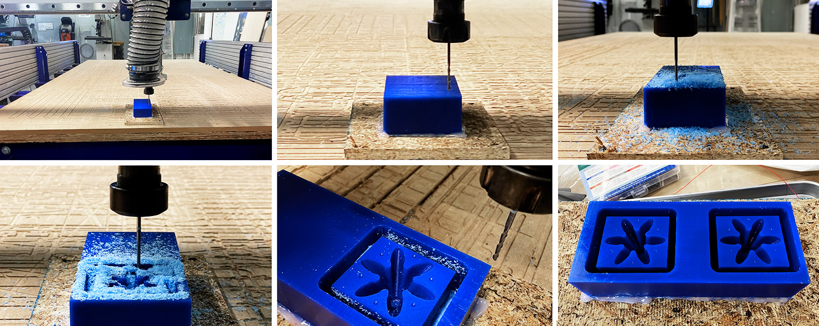
The photos below show the process of milling our wax block using the 3-axis milling tool on the large Shopbot, since the desktop one was being used by another student simultaneously. The photo on the bottom right shows the final milled mold. Since we had the space and time, we replicated the structure twice to be able to cast both parts of GRACE in one go. We also applied silicone release agent spray on the mold before casting to ease the demolding process.
Tapping the Holes
Using a 2mm drill, we tapped the holles a little deeper to ensure a clean interfacing between the two mold parts.
Cleaning the Chips
Using high pressure airgun at the molding/casting workshop at CBA shop, we cleaned the wax chips from the mold to have a clean mold that would hinder any artifacts in the final design. This was not easy as the chips that resulted from the cnc process were stuck on the surface of the mold. When air gun did not suffice, we used IPA to clean the surface and the applied pressurized air.
Applying Release Agent
For silicone to be easily removed from the mold, we applied release agent on both mold parts that would interface with silicone. This improved the removal process slightly but not significantly, and even without it we were able to easily removed the mold apart in our final design iteration with the holder pieces in the FDM printed red top insert (see image below).
4. FINAL PROTOTYPE: PROPRIOCEPTIVE GRACE ACTUATOR
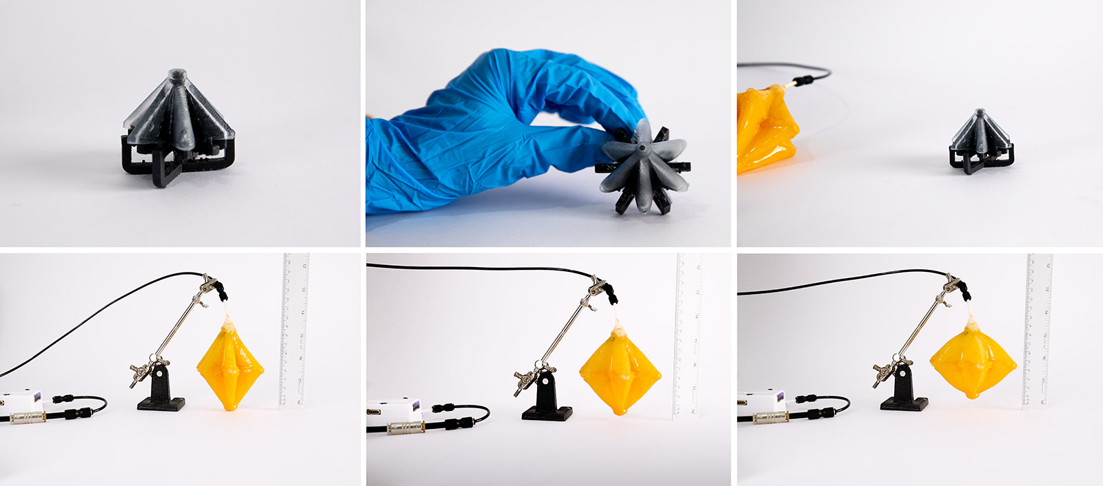
The photo below shows an assembled GRACE where we used Smooth-On EcoFlex 30A for casting and Smooth-On SIL-poxy rubber silicone adhesive for bonding the two parts together. We also applied a thin layer of yellow colored smooth-On EcoFlex 30A layer on the outside both for aesthetics and extra sealing.
It is controlled at 3 bars of air pressure for faster response (flow rate), however due to the softness of the silicone (30A) the stored energy in the actuator was too little to have a fast release/return. Hence, in the coming weeks we aim to use more rigid materials or alternatively print it on Formlabs while also integrating the embedded sensor channels in the print for resistive and/or capacitive sensing.
GRACE Actuator + FlowIO
In order to test this first primitive structure, we used FlowIO soft robotics platform developed by Ali Shtarbanov of the MIT Media Lab, which I have been collaborating on the device together with him for a while now. The sequential inflation is shown in the below.
Stretchable Sensor
The future of soft robots is adding both proprioception and perception to the robot so it can smartly react to changing environments. We wanted to add some level of proprioception to our grace structure by embedding a flexible strain sensor. We used carbon conductive grease from MG Chemicals as the main sensing material for resistive -type of sensing. We created a tape senticl mask to make it easier to pattern the great on top. Then we used thin wires to tether the sensor and finally encapsulated it with a thin layer of silicone.
Proprioceptive Grace
For the sensor readout circuit, We employed a voltage-divider circuit using a commercial reference resistor and our sensor as the unknown resistor. We used Arduino Leonardo as the microcontroller and the Arduino IDE for the serial plotting. Below is a video of the sensor output as a result of inflating and deflating the soft robot.