INTRODUCTION

This week we're introduced to a variety of input devices. I experimented with differnt types of custom-made liquid metal-based (EGaIn) resistive and capacitor sensors that I fabricated, as I will likely use either one of these for my final project. I first designed a board for each input mode; namely a wheat stone bridge for resistive sensing and step response for capacitive proximity sensing. Among them, I only managed to get the resistive sensors to read out properly while sadly I haven't completed the capacitive sensing as late in the process I learnt that the proximity sensing library was not compatible with the IC of choice, SAMD11C. Therefore I plan to replace the SAMD11C with 21C after the class is past as I am more inclined towards using the capacitive sensing for the final. More details about the fabrication process of the sensors and the boards as well as the dozen issues I came across can be found in the following sections.
For the sensor fabrication, I used direct ink writing, filling and twisting, and finally knitting for making various strain gauges. For capacitive sensing, I continued working on my molding and casting project to try out a different sensing method which is capacitive sensing, for achieving proprioception and closed loop feedback. For circuit design and fabrication, I worked together with Wedyan where we distributed roles of designing and overlooking the two circuits; for resistive and capacitive sensing. We based our designs on Neil's boards for RTD (for resistive) and step response (for capacitive).
Additive manufacturing methods for elastomers today still remain either challenging or expensive, and therefore we decided to take another fabrication approach to make GRACEs using molding and casting. This method is especially useful for making modular constructs as the mold allows casting the same structure over and over. This week's assignment made a great excuse to replicate this work, and augment it with resistive sensing elements for making proprioceptive actuators.
1. LIQUID METAL-BASED HIGHLY STRETCHABLE RESISTIVE STRAIN SENSORS
Soft and stretchable sensors have the potential to be incorporated into soft robotics and conformal electronics. Liquid metals represent a promising class of materials for creating these sensors because they can undergo large deformations while retaining electrical continuity. Incorporating liquid metal into hollow elastomeric capillaries results in fibers that can integrate with textiles, comply with complex surfaces, and be mass produced at high speeds. Liquid metal can be either directly printed or injected into hollow and extremely stretchable elastomeric hollow channels and the resulting sensors can be used for resistive or capacitive sensors of torsion, strain, and touch.
Gallium-based LMs, such as eutectic gallium indium (EGaIn, 75% Ga and 25% In), offer a promising way to create such sensors.[10]EGaIn has low toxicity,[11] negligible vapor pressure at room temperature, and low viscosity. The latter property allows LM to flow in response to deformation, whereas solid metals are stiff and prone to fail at small strains. Embed-ding LM in elastomer decouples the elec-trical and mechanical properties; that is, these composites have the electrical prop-erties of the metal and the mechanical properties of the elastomer.
1.1 DIRECT INK WRITING WITH MYCRONIC DESKTOP DISPENSER
FABRICATION OF LIQUID METAL PATTERNED SENSORS
Flexible strain sensors have been widely used in wearable electronic devices for body physical parameter capturing. However, regardless of the stretchability of the sensing material, the resolution of small strain changes or the hysteresis between loading/unloading states has always limited the various applications of these sensors. In this paper, a microfluidic flexible strain sensor was achieved by introducing liquid metal eutectic gallium indium (EGaIn) embedded into a wave-shaped microchannel elastomeric matrix (180 μm width × 70 μm height). The microfluidic sensor can withstand a strain of up to 320% with negligible hysteresis.
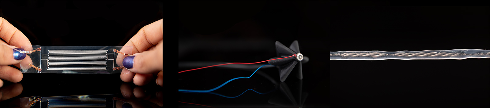
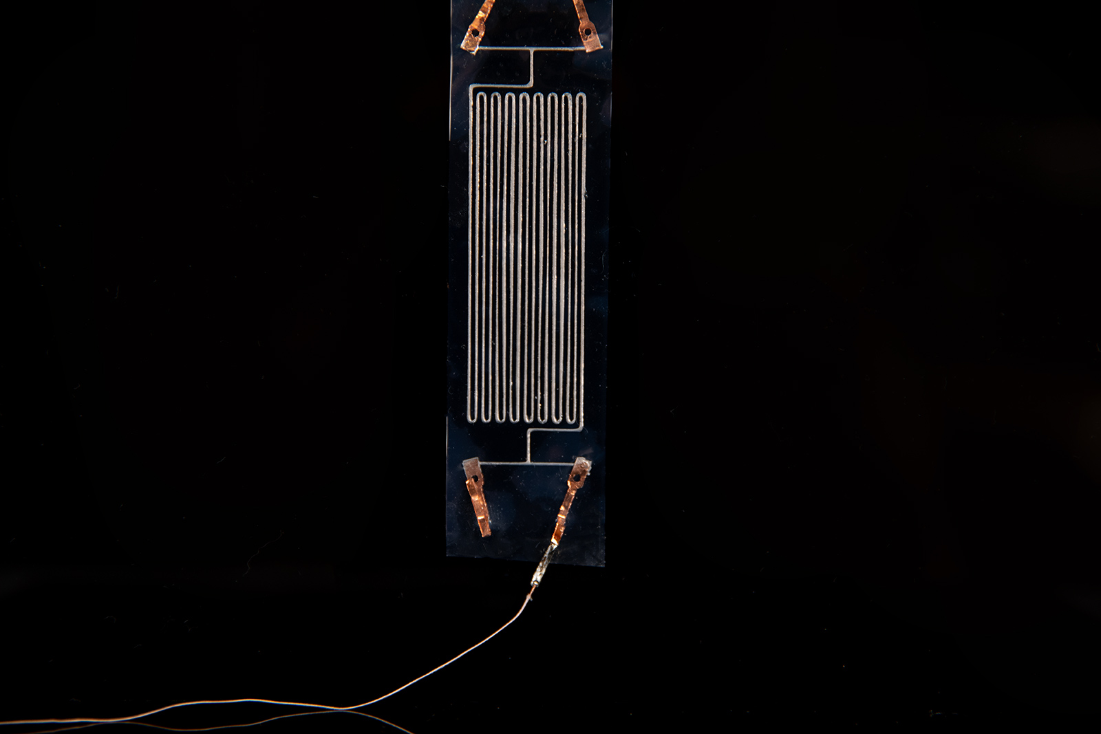
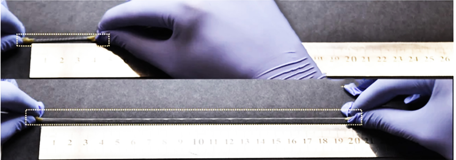
For the fabrication process, I first casted a sheet of PDMS (Sylgard 184) with 100 micron thickness using a doctor's blade. After degassing to remove all bubbles, I cured the sheet PDMS in the oven at 60 degree C for 2 hours. Once ensuring that the PDMS is fully cured, I placed it under the Mycronic desktop dispenser , which is an amazing piece of equipment for contact or non-contact direct ink writing of low-high viscosity fluids (e.g. solder paste, elastomers etc). I used a 100 micron ID nozzle and uploaded a serpentine pattern to increase the resistance in the LM channels as gallium-based LMs have high conductivity and often used for interconnects in stretchable electronic circuits. In this case, I utilized the thin channels for wearable sensors which is an active area of research.
RESISTANCE RANGE
The final R(0) of my sensor was 16.8 Ohms which is fairly small however still possible to read in a circuit which I will go into detail further below. However the resistance change was pretty good, with 60% of strain the resistance went up to 30 Ohms and further up to 45 Ohms at 100% strain. Due to the high stretchanbility of these sensors, I managed to stretch it up to 200% to observe potential hysteresis that might occur however I returned back to R(0) = 16.8 Ohms each time which is promising for low-no hysteresis in these sensors. More cyclic tests need to be done before claiming no hysteresis but often LM-based sensors are known to demonstrate high yields with little or no hysteresis so I was really happy with these results! The resistance change read on the multimeter can be seen in the below video at 0-60% strain test.
1.2 TWISTED LM-FILLED MICROTUBULES for SUPERELASTIC FIBER SENSORS
FABRICATION OF MULTIMODAL LM-BASED FIBER SENSORS
Stretchable sensors with high sensitivity, no hysteresis, high conductivity and a fiber conformation have considerable potential application in stretchable electronics, soft robotics and smart clothes—especially, for example, in implantable biomedical fiber-shaped sensors. The LM fiber sensor presents huge potential for emerging applications in fields such as stretchable electronics, human motion monitors, and smart clothes, and especially in the development of implantable biomedical fiber-shaped sensors. In order to increase R(0) and sensitivity of the LM-based sensors from the previous stretchable sheet sensor test, I referred to a very simple injection and twisting method that is well-covered in this paper from Dickey group. The paper describes the use of stretchable hollow elastomeric fibers filled with liquid metal (LM) as soft and stretchable capacitive sensors of torsion, strain, and touch. I used the same approach for making resistive sensors following my previous samples to enable different embodiments of LM-based strain gauge.
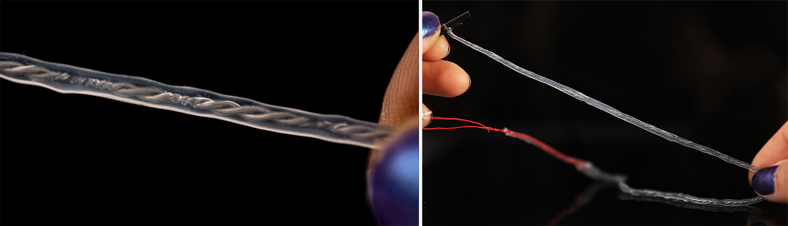
The fabrication process is rather simple: First the EGaIn is filled in a syringe with a tip of OD= 300µm. It should be ensured that there are no bubbles left in the syringe as this will present issues while injecting the liquid metal. For the encapsulating tubing, I used a 40A TPU tubing with ID = 300µm, OD = 300µm as I readily had this tubing available from an extrusion company at NH, TekniPlex. Then, I cut a tubing of 1 meter length and keeping both ends of the tubing open I injected the liquid metal into the tubing at a speed of 10mm/s. One can go slower to ensure not introducing any air into the tubing during filling as well as the LM having continuous contact with all surfaces in the tubing as well as filling the hollow channel. After the tubing is filled and a little bit LM is dripping from both ends, I inserted the connection copper wires to both ends and sucked back the excess LM with the syringe as it will hinder adhesion. Once the wires are stabilized in place, I injected little amounts of fast cure epoxy to seal the ends. This process is much harder and less stable when the tubing material is silicone as an sealing that will be achieved can easily come out as a block once enough pull force is applied to the connectors which is a long-standing major issue with stretchable sensors and electronics.
TWISTING SETUP
After the epoxy is fully cured and ends are sealed, first I measured the readout resistance to be only 6 Ohms and the change in R at 100% strain was around 2.5 Ohms. To increase R(0) and sensitivity, twisting is used as a method to introduce a geometric "necking" behaviour in the tubing, as once the fiber is twisted, this will reduce the ID as well as create regions of stress on the LM channels. This is the main principle and reason behind introducing twisting to these fibers. In my case, I folded the fiber into two equal lengths, and first twisted the insulated connection wires to stabilize the connection part. After that, I inserted a thin stick to the other end of the LM filled tubing, and started twisting manually. This was done in a vertical setup, applying 20% stretch to the tubing while doing so.
Through this process, it was also clearly observable that as the twisting turns were increased, the resistance increased. Hence, the fabricated sensor proves to be also a good torsional sensor for applications. However, strain and torsion cannot be decoupled and either one or the other will need to be used when applied to use cases. I observed the increase in resistance while applying 1, 5, 10, 20 and 30 turns. At 30 turns, the R(0) went up to 900 Ohms (close to 1K) which is a good resistance to work with in most circuits as the R gets higher, the interference of noises from the circuit would have minimal effect on the readout.
As a final step, to ensure that the fiber would not untwist, I coated it with a thin layer of PDMS, which took a day to cure as I could not put my twist setup in the small oven we have at the lab hence I had to cure it at room temperature. For this reason and to avoid introducing too much restriction to strain due to PDMS's higher young modulus, I coated the outermost layer using Ecoflex 30. After 2 layers of coating, I found that the pre-stored torsional energy was too strong that the fiber wanted to untwist, hence I added a bulky 3rd layer of Ecoflex 30 which made the sensor look ugly but in terms of functionality, it did the job. Finally I had a totally cured and secured, twisted microtubules filled with LM for both torsional and strain sensing.
RESISTANCE RANGE: Torsional and Strain Sensors
Finally, I characterized my sensors and found that at 100% strain, R went up to 2.5K and was super sensitive to even 1% of strain. This makes a good case for wearable sensors where minor or major motions can be deteced with high yield. I was happy with the results but the sensor fabrication method can be made much less DIY as well as achieving more pretty looking fiber sensors! Further, being able to extrude my own tubing with smaller inner diameters would reduce the starting resistance as well, so with much less number of turns, one can still achieve higher resistance as high as 1K.
Advantages:
- Super easy to make
- Can be made in meters long lengths
- Can be made very thin hence knitted and woven into textiles for truly wearable sensors
Disdvantages:
- Basic sensors are possible, for more complex e.g. multilumen structures, custom extrusion would be required
- Secure end-sealing (soft-rigid interfacing) is always an issue
- Gallium should be used in precaution, despite the fact that there are no known health hazards
1.3 KNITTED LM-FILLED MICROTUBULES
FABRICATION OF KNITTED SENSORS
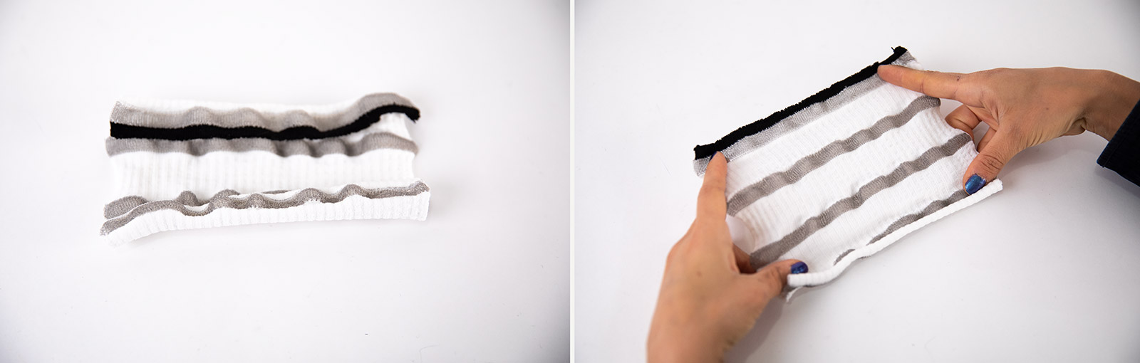
The process is similar to the previous torsional/strain guage LM fibers however this time I used a higher young modulus tubing as the tubing would go through a machine and is vulnerable to being punched by the needles on the knitting bed. Hence, PVC tubing was used with an ID = 0.25mm and OD = 0.6mm. I made a basic jersey knit on the Brother KH940 knitting machine, starting with a regular black cotton yarn and changing into the LM-filled yarn in the middle rows. The knitting was fairly simple and smooth as I had tested this before - often plasticy materials are pretty ok to knit with as long as they have a suitable bending radius. In this case, since the tubing was fairly small, it almost behaved like a regular plastic yarn.
RESISTANCE RANGE
In the first test, I had issues with reading out any resistance (likely way too high for the multimeter to read) due to disconnect in the LM channel while casting off the knit from the machine. In the second iteration (image below) I read R(0)= 45 Ohms and upon stretching it, this value increased up to 105 Ohms. I need to properly characterize this textile sensor however the behaviour seemed pretty linear however with some hysteresis. In this embodiment, the tubing is PVC than TPU as I needed less elasticity in the tubing to be able to knit without any blockage of the LM channels. Hence, the PVC does not fully return to its initial length above 30% strain so this sensor is much more prone to hysteresis and low yields.
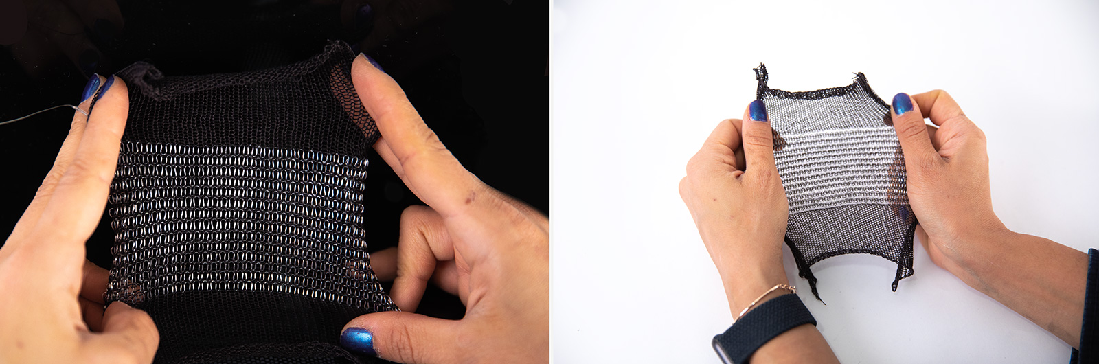
I also wanted to try knitting with this yarn on the Shima Seiki machine using the inlaying method however I was scared to introduce this to the machine as it would be very arduous of a job to clean it afterwards. Hence, I used an off the shelf resistive yarn to knit a piece on the Shima WG MACH2XS and had a successful result of periodic strain gauges embedded in the knitted structure. It is quite stretchable and soft, however one interesting behaviour was that the resistance actually went down as I stretched the fabric. I had come across a paper that talks about the reverse behaviour in detail, but my hypothesis is that there is actually more contact between the loop stitches than that of the relaxed state, in the vertical axis of the knit. Hence, there is less resistance in the global structure.
Next Steps:
- Torsional sensors are cool and the LM-based one is very linear! Never thought about a use case for them but I will consider for further research in fiber based sensors.
- Inverse behaviour of the R in the knitted textile sensor using off the shelf resistive yarn deserves further investigation to confirm the hypothesis.
- LM-filled tubing was really easy to fabricate however when I replicated the capacitive sensor, I failed. Hence I need to better understand the parameters that matter for the capacitive sensor the authors from Dickey group produced.
2. LM-BASED CAPACITIVE SENSOR
FABRICATION: 3D PRINTED "GRACE" ACTUATOR
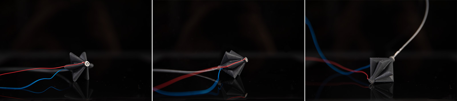
Following up on last week's prototype, the pleated PAM actuator, I 3D printed on the Formlabs printer using flexible resin. I had to redesign some parts to make space for wiring for the sensors as I decided to go with capacitive plates on the two ends of the actuator for closed loop control. I hoped that this would be a very straightforward process, but I was totally wrong!
PATTERNING LM RINGS & SEALING WITH EPOXY
The print(s) came out perfectly and I printed the actuator in various diameters from 2cm up to 6cm. 2cm actuator was the cutest as I love everything miniaturized, however 6cm one was the easiest to work with. Once the print was fully cured under UV light, I placed the wires inside the hollow parts at the top and bottom sections of the structure. Then I stabilized them with adding a drop of epoxy just on the wall of the actuator where I drive the wires along. Once the wire was stable, I patterned the top plate with EGaIn, then enclosed with epoxy. After the top plate was fully cured, the same process was applied for the bottom plate.
Learning Outcomes
NEVER EVER USE MATERIALS THAT HAVE EXPIRED SHELF LIFE (EVEN IF THEY'VE NEVER BEEN OPENED!)
3. PCB DESIGN, FABRICATION AND EMBEDDED PROGRAMMING
3.1 RESISTIVE CIRCUIT USING WHEATSTONE BRIDGE
I designed a wheatstone bridge circuit based on Neil's RTD circuit and just replacing few components. Instead of the ATTINY45, I used SAMD11C chip similar to my previous PCB design/embedded programming week(s), a 2x5 Connector, and the USB Connector. Additionally, I changed the sensors in the circuit to lower R values to read out a larger range given that my LM patterned sensors have an R(0) of 17 Ohms. Based on the mid-range value (25 Ohms), I used David's R calculator that he kindly shared with us, and defined the remaining three resistor values to be 25 Ohms to provide me the largest range.
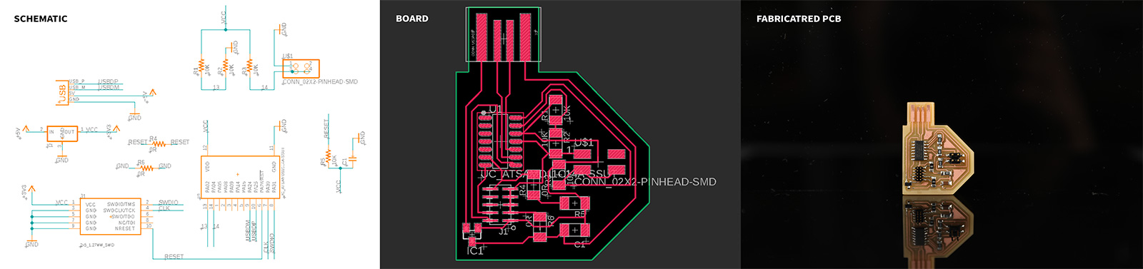
Hence, I stacked 2 x 50 Ohm resistors (parallel connection) to achieve this value in all three resistors. However, this loaded the voltage regulator to its upper limit, therefore I had overheating and a little bit of smoke (!) coming out of my voltage regulator. As Neil suggested later on, I could have just replaced this regulator with the higher current one, but instead I replaced the resistors to avoid overheating. However this was a tradeoff between having less sensitive of a circuit and less observable changes in the readout compared to using 25 Ohm resistors. Hence, the readout was not great but still working as it should.
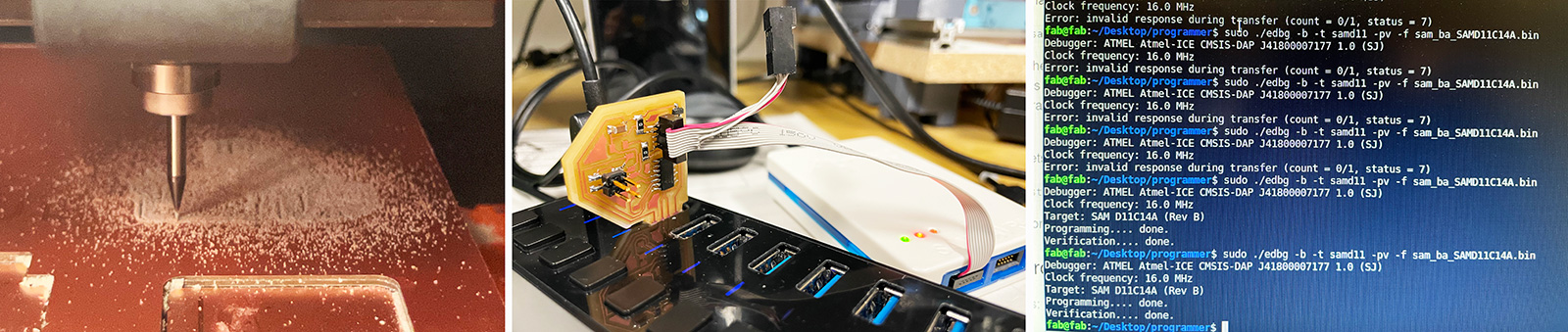
Then I replaced the resistors with 1K ones for my twisted LM fiber sensor for torsional and strain sensing, which has an R(0) of 0.95 KOhms. This worked perfectly as can be seen in the video below, however I need to do signal processing to reduce the noise from the circuit and the environment (and avoid spikes introduced from my hands each time I accidentally touch the connector wires!)
3.2 CAPACITIVE SENSING WITH STEP RESPONSE
For my capacitive sensor circuit, I used the step-response approach where I configured a pin as the transmit/send pin and another as the receive pin with my sensor attached with a large value resistor to the receive pin. The sensor is composed of two LM-based capacitive plates, disturbing the electric field and increasing the capacitance.
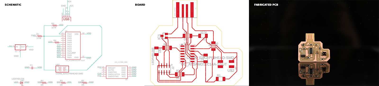
I also tested the output of my fabricated sensor using an Arduino board and a 1M resistor on a breadboard. After confirming that I could get detectable reads from the ADC, we started with the PCB design. We used the SAMD11C as our microcontroller and referenced Neil's example for step-response circuit with the copper pads as the sensing plate. It worked perfectly fine with the copper plate, replicating Neil's example however I got no readout from my smaller area LM plates for proximity sensing. However, after presenting in class, Neil had some great suggestions so I may not need to change to SAMD21 chip afterall (which I was ready to do and I might still do it to explore that chip)!
Learning Outcomes:
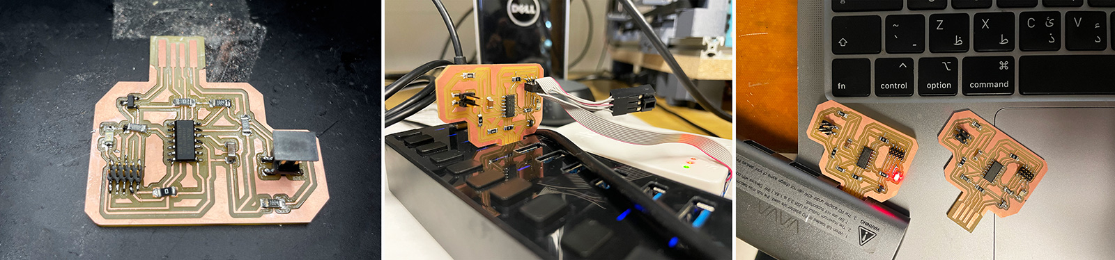
- I experienced many issues and failures during the fabrication process of the sensors as well while connecting sensors to the boards.
- While I was connecting my sensors to the board, I mistakenly pulled the header connector, which removed the pads entirely from the board. I needed to perform some micro surgery on the board with some jumper wires. However, i think i lost GND connection at some point and now the board has stopped being recognized by the computer. I will debug it and see where the issue is after the class.
4. REVISITING PROPRIOCEPTIVE GRACE ACTUATOR
Despite I couldn't get a readout from the step response circuit, my actuators worked perfectly fine at similar pressures from last week, 4 bars, and much faster as I have fundamentally scaled them dowm. I will add a video later this week hopefully getting my cap sensors working and having the readout with the modified circuit design and code upon Neil's suggestions in the class.