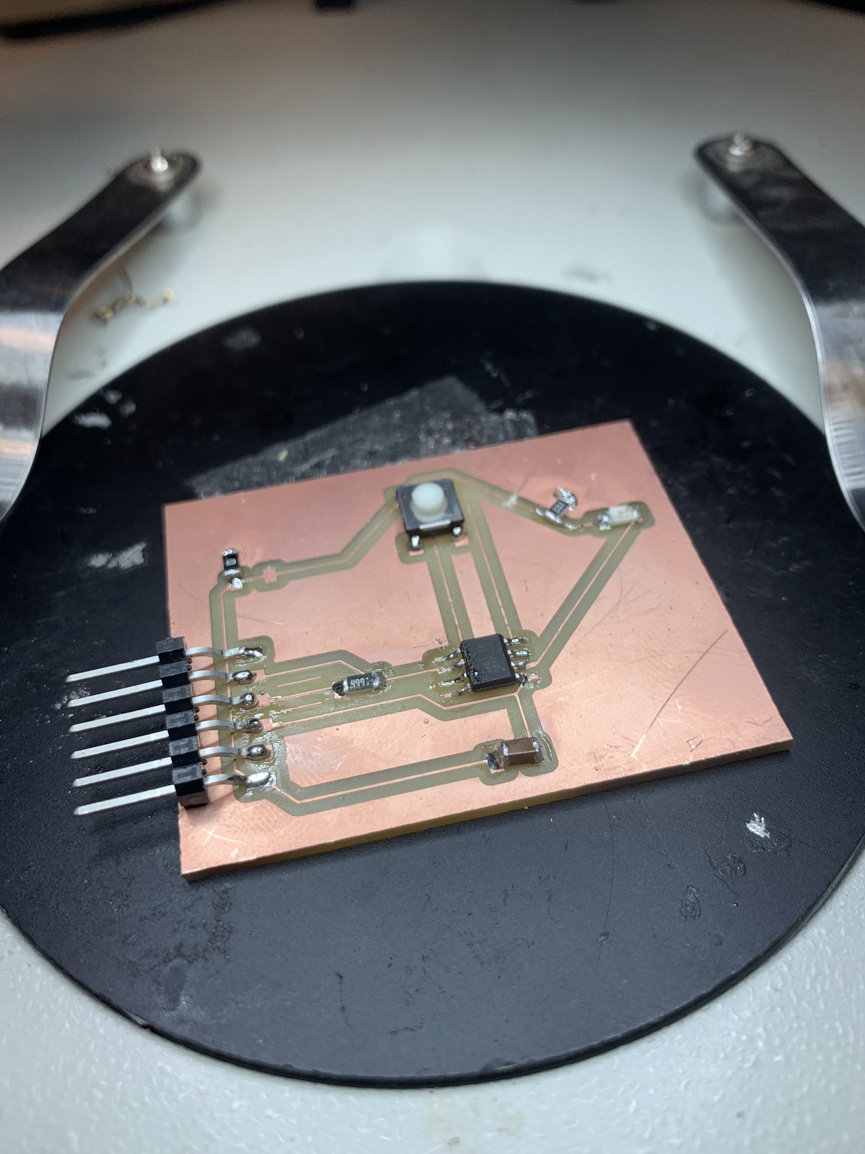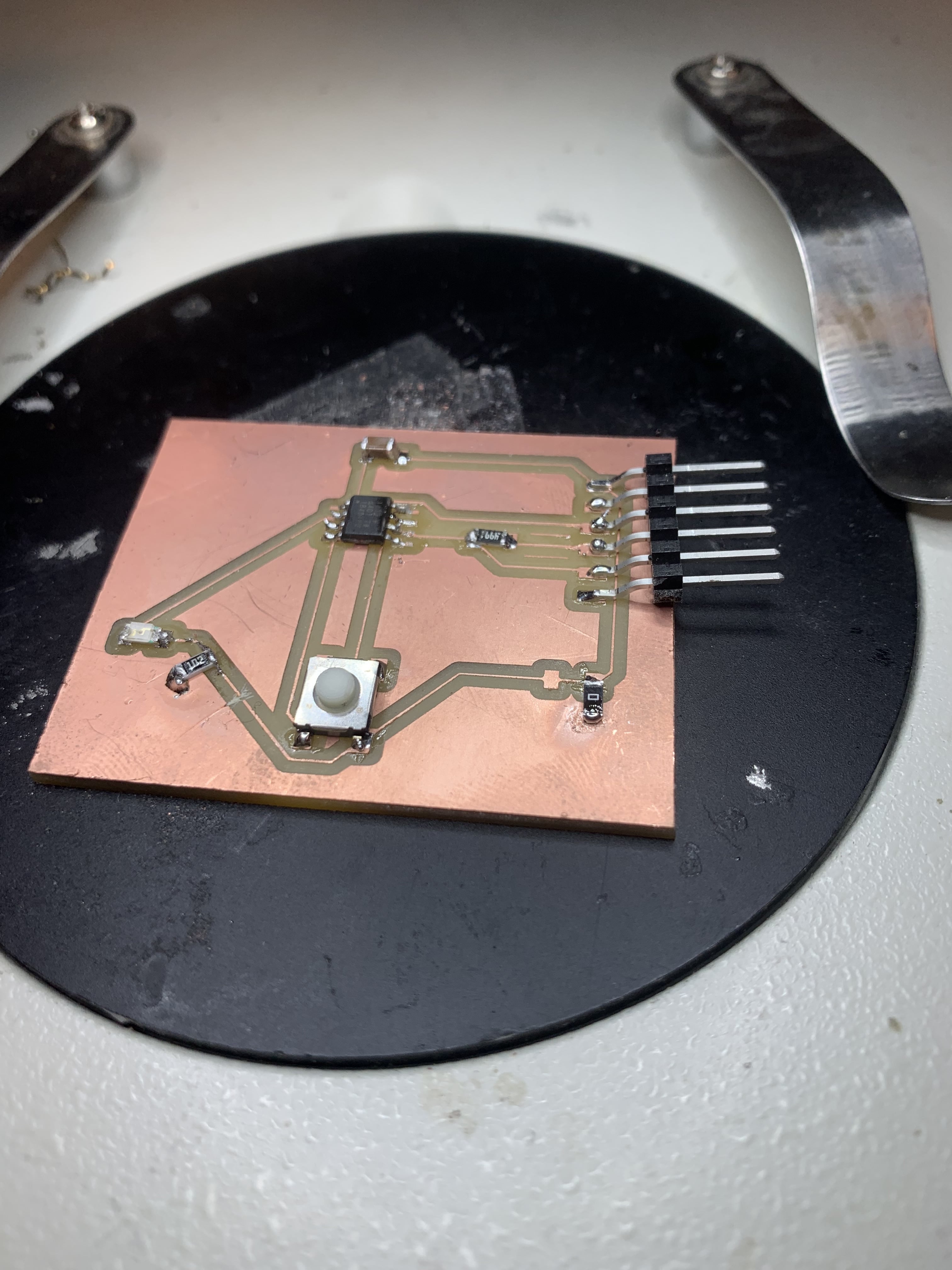

The purpose of this week was to get more experience with electronics. Specifically, to design a PCB board, produce the trace and outline files, mill it, solder it, and then program it. Given my very limited experience with electronics, I thought it best to keep things simple for now and build up. So I decided to make a board with a button and a light as my hello world.


For the PCB design I used used Autodesk EAGLE with Fusion 360. Even though I had never done anything like this before, it is possible to get the hang of it fairly fast. A few good things to keep in mind:


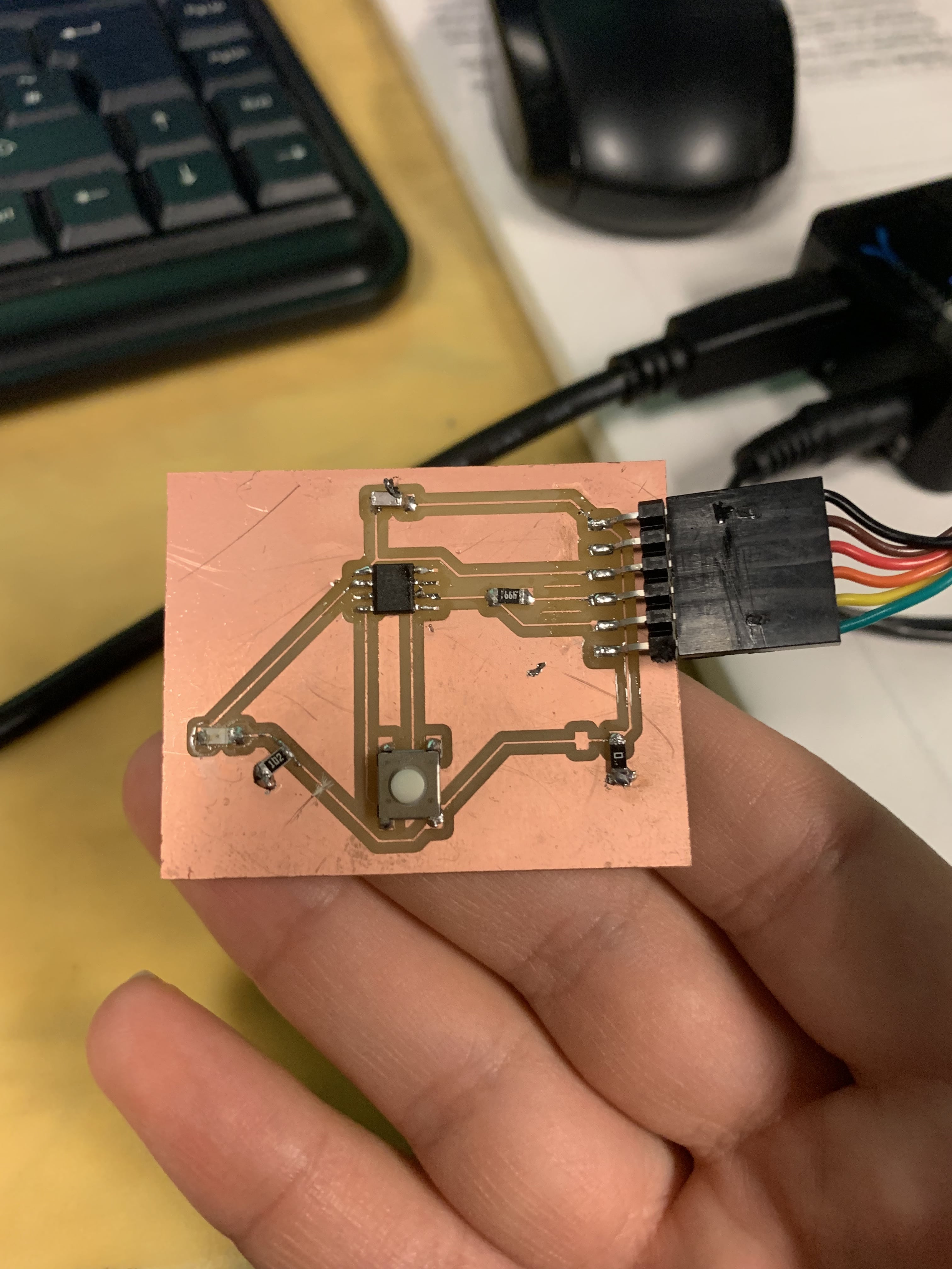
As this was only my second time soldering, it was quite exciting to see everything working in the end. Some brief pointers from what I've learned about soldering is to first put a bit of solder on the pad, and then place the component onto that pad (while touching it with the solder gun). As soon as the solder melts, one can place the end of the component onto the pad and try to align it correctly. After that it is very important to put solder on the OTHER side, so as to stabilize the component, before fixing the original solder pad. Some more images included below.


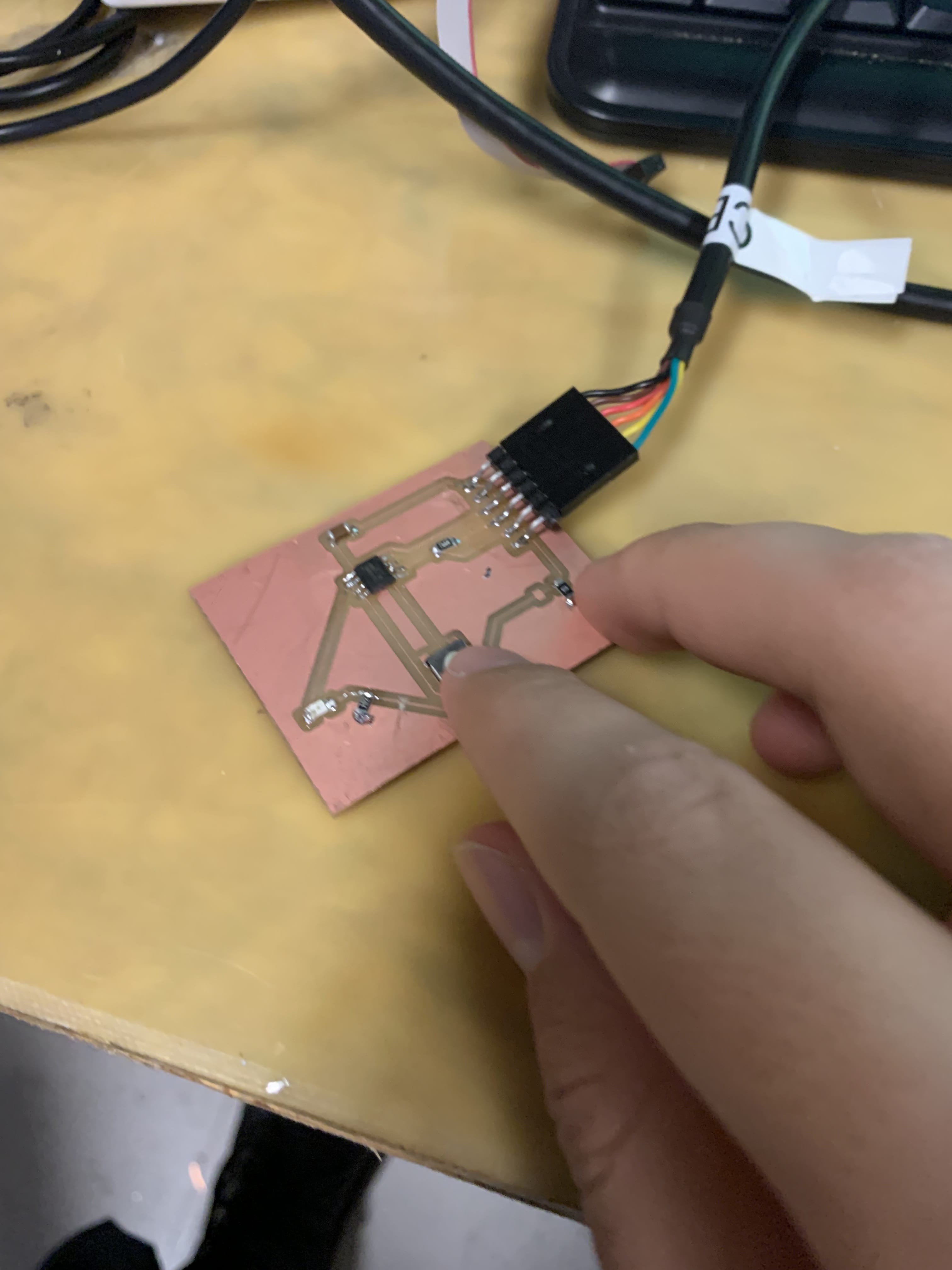
Finally, it is time to program the board. Thankfully, the UPDI protocol makes this quite easy as we don't have to bootload anything, but rather can directly upload the code using the Arduino IDE. When connecting the FTDI cable it is important to remember that black is GND. The other pins should follow. To control LEDs, one needs to use the digitalWrite() command to set the value of the LED pin to either LOW or HIGH. Coupling that with input from the button, we get a nice board with an LED that light up when the button is pressed, and is off otherwise: