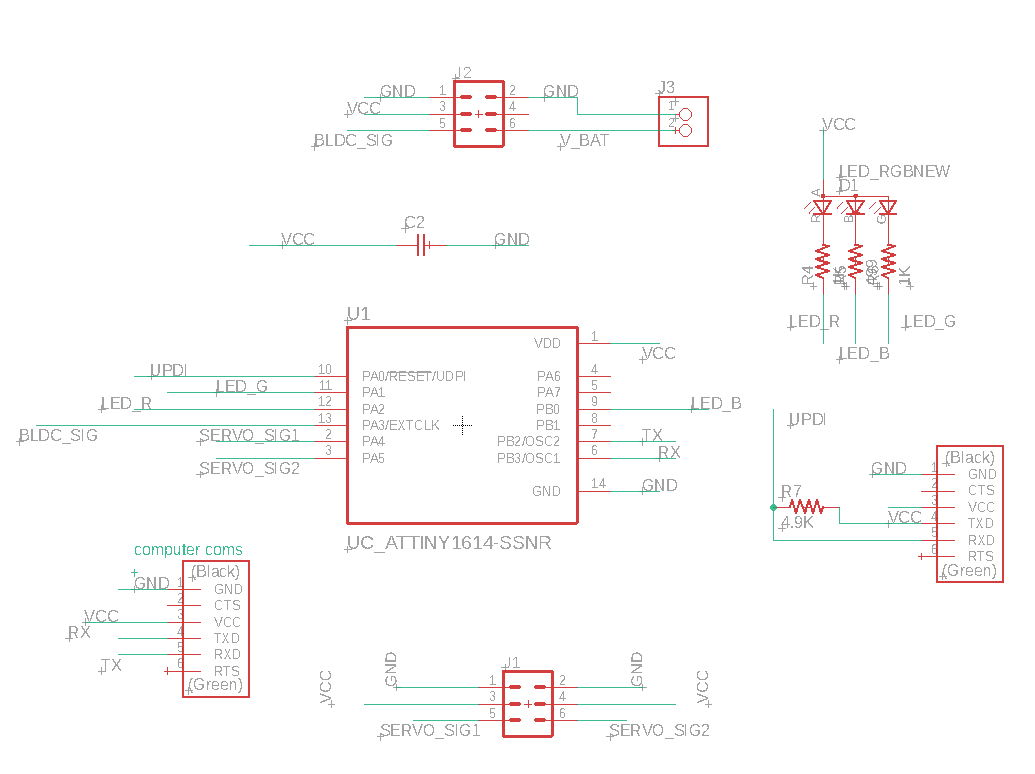
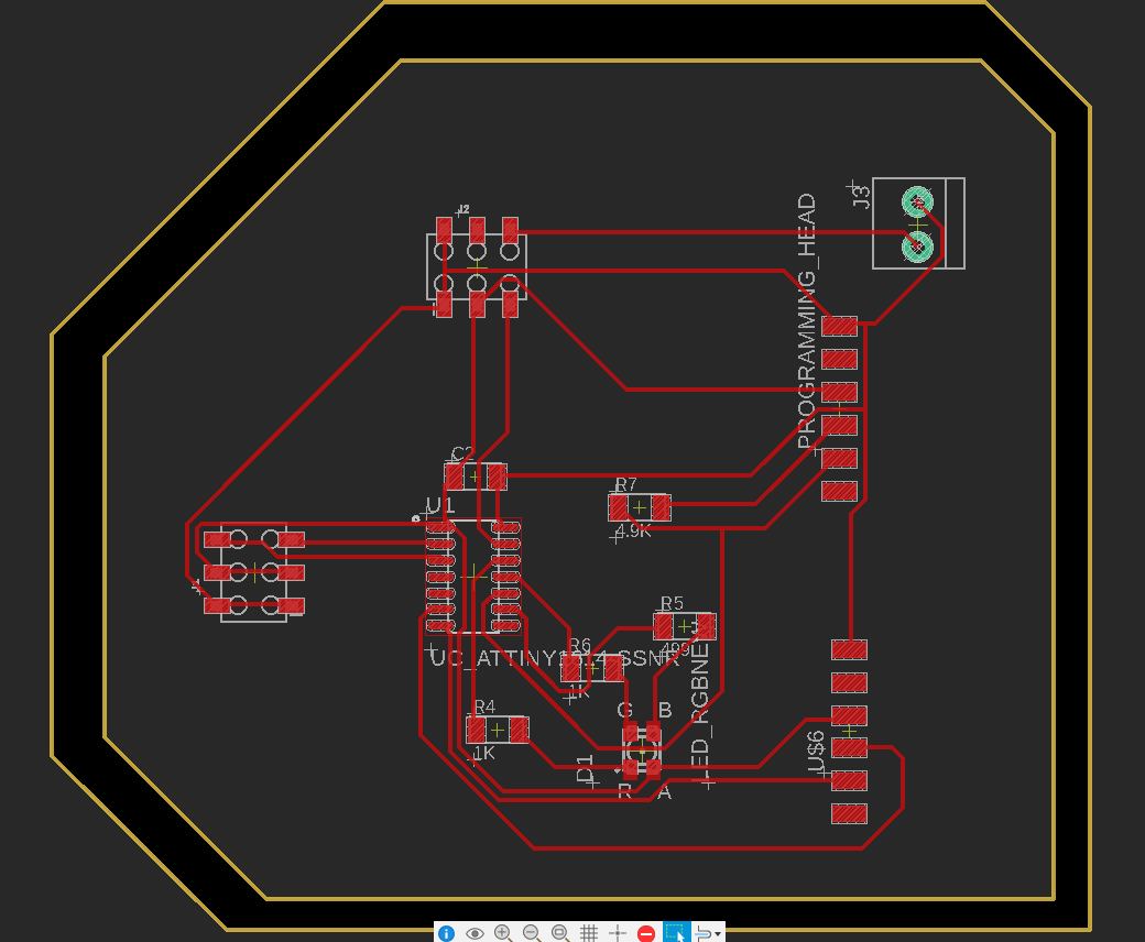
This week was output devices. As the name suggests, the goal is to make a board with an output device. Given that my final project is to make a plane, I decided to experiment with different motors. For remote-control planes such as the kind I will be making, we generally need two different types of motors: a brushless DC motor (BLDC) for the propeller, and several servo motors to control things like ailerons, elevator, etc. I also wanted to add a light to help with debugging down the road, and this time around decided to experiment with an RGB LED. These LEDs are a bit trickier though as they require three resistors instead of just one. This board is a good reference. Here are the schematic and pcb designs:
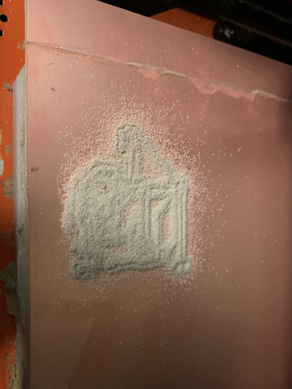
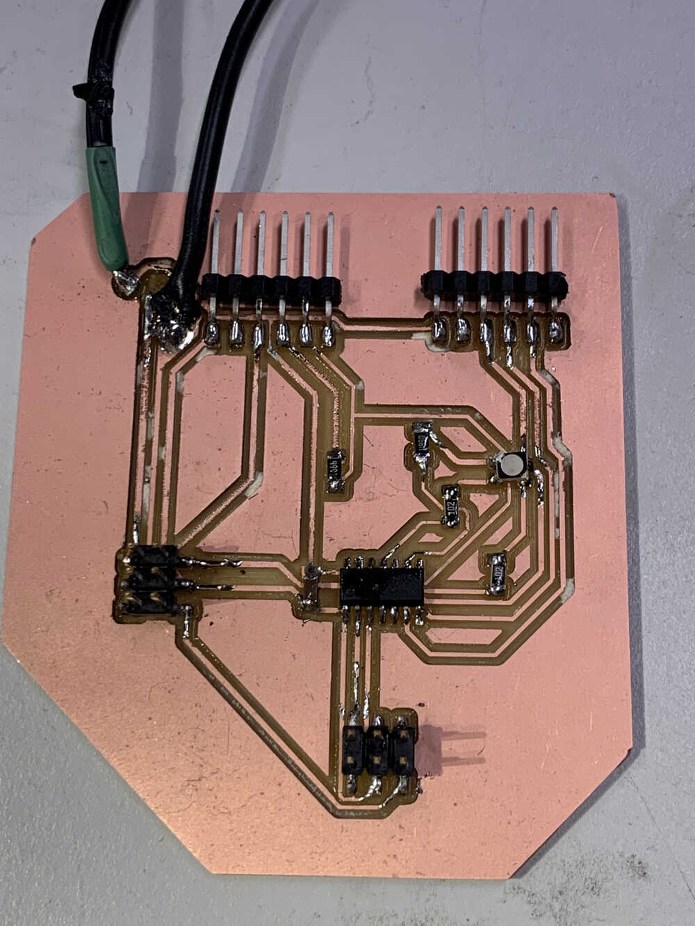
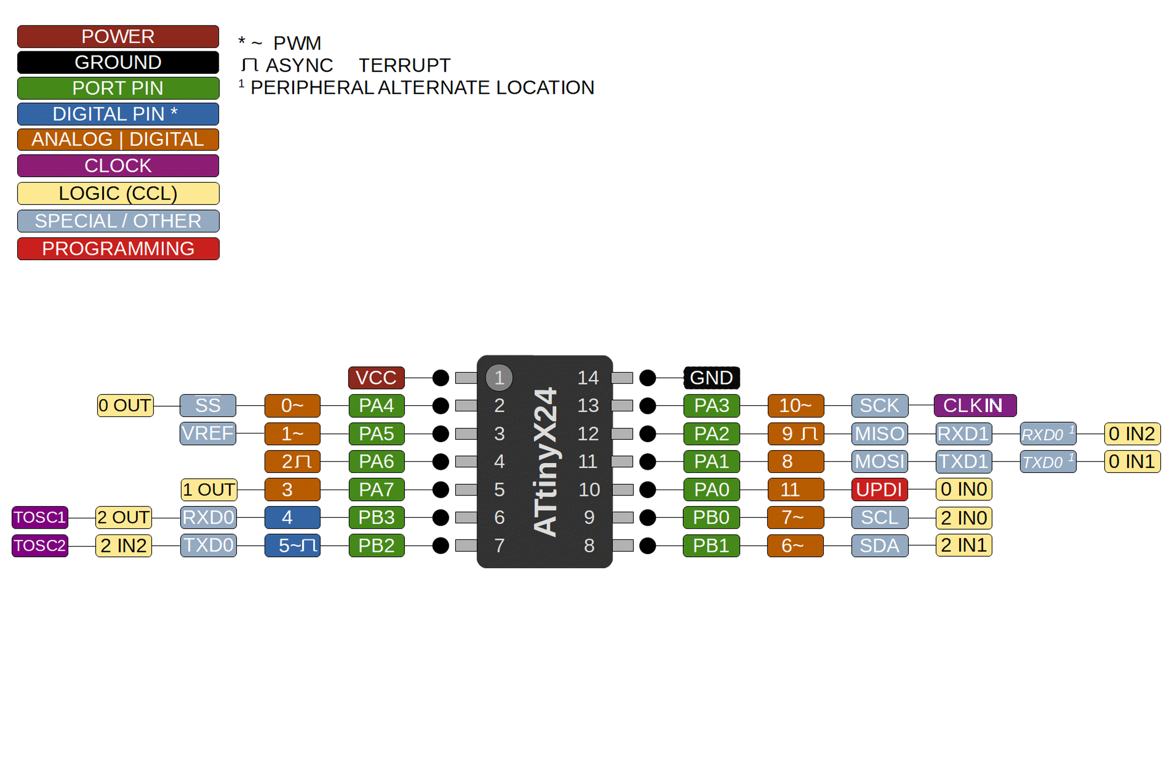
For our design this week we again used Autodesk EAGLE with Fusion 360. We also had to upgrade to the larger ATTINY1624 which has more pins. This has a good pinout diagram of the microcontroller. The rough idea for the design is to power the servo motors with power from the FTDI cable, and to power the Electronic Speed Controller (ESC) direct from a battery source. We also need to add a second communication port. We need regular RX and TX signals to be able to print to the serial monitor, which means the UPDI signal wire will not work for that. That is why we added a second programming head. Finally, it is also important to keep in mind that all servos and esc need to have common ground with the board, so one needs to ensure that all GNDs are connected. After milling and soldering we see the following.
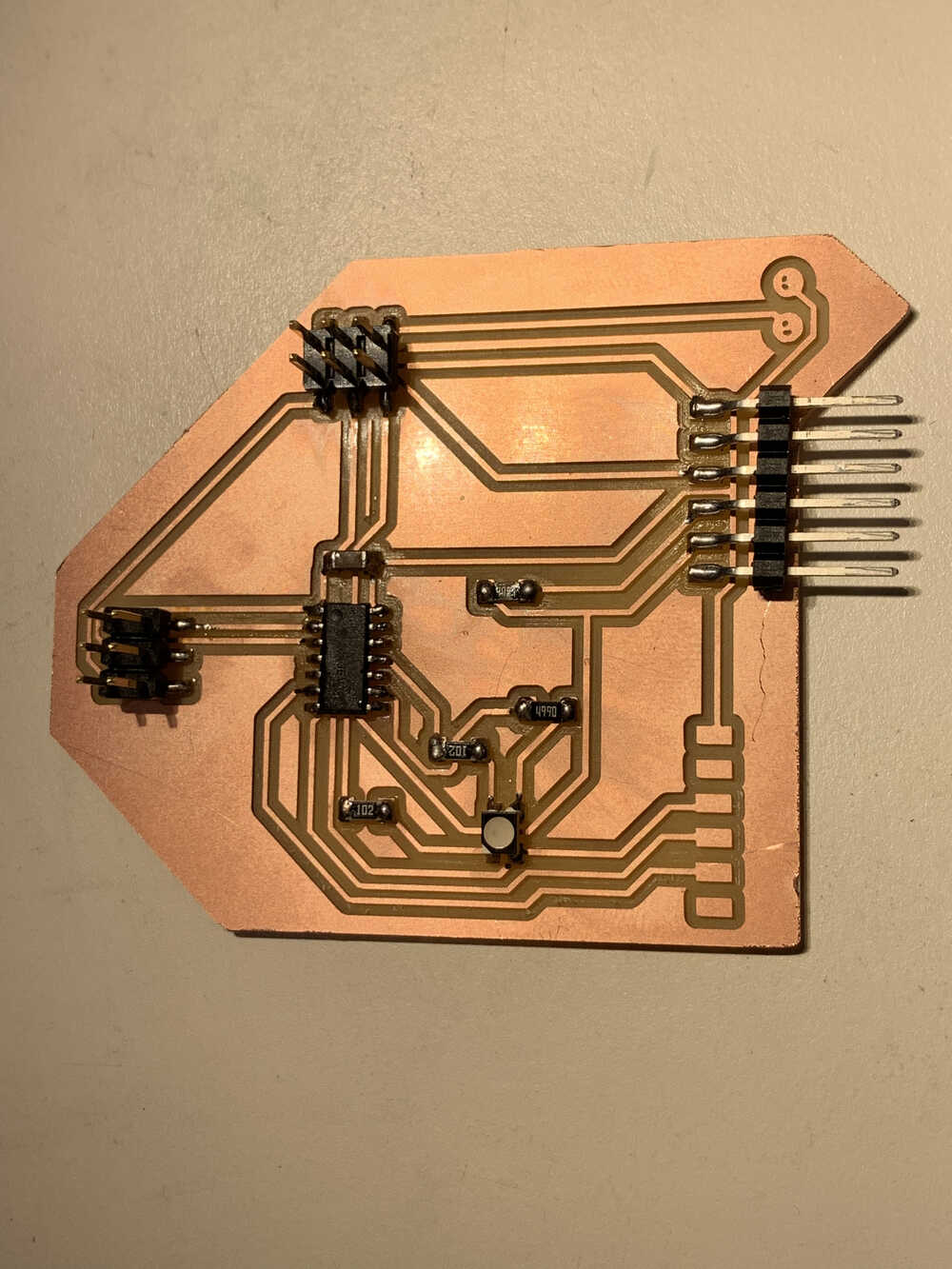
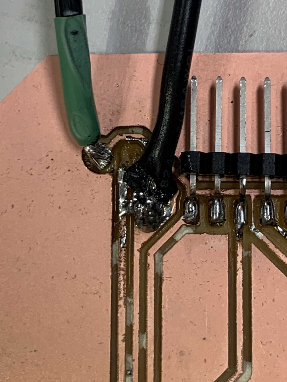
We also need to solder another power source for the ESC, so we tried taking a cable with 5V and soldered it onto the board. As we can see from the below pair of images, that is a harder solder task.
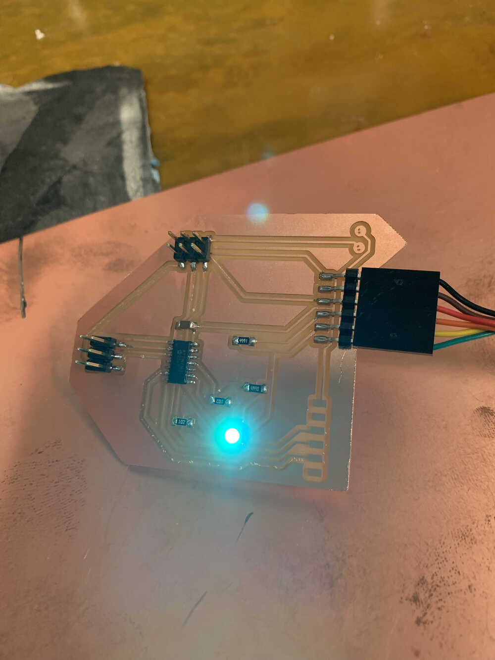
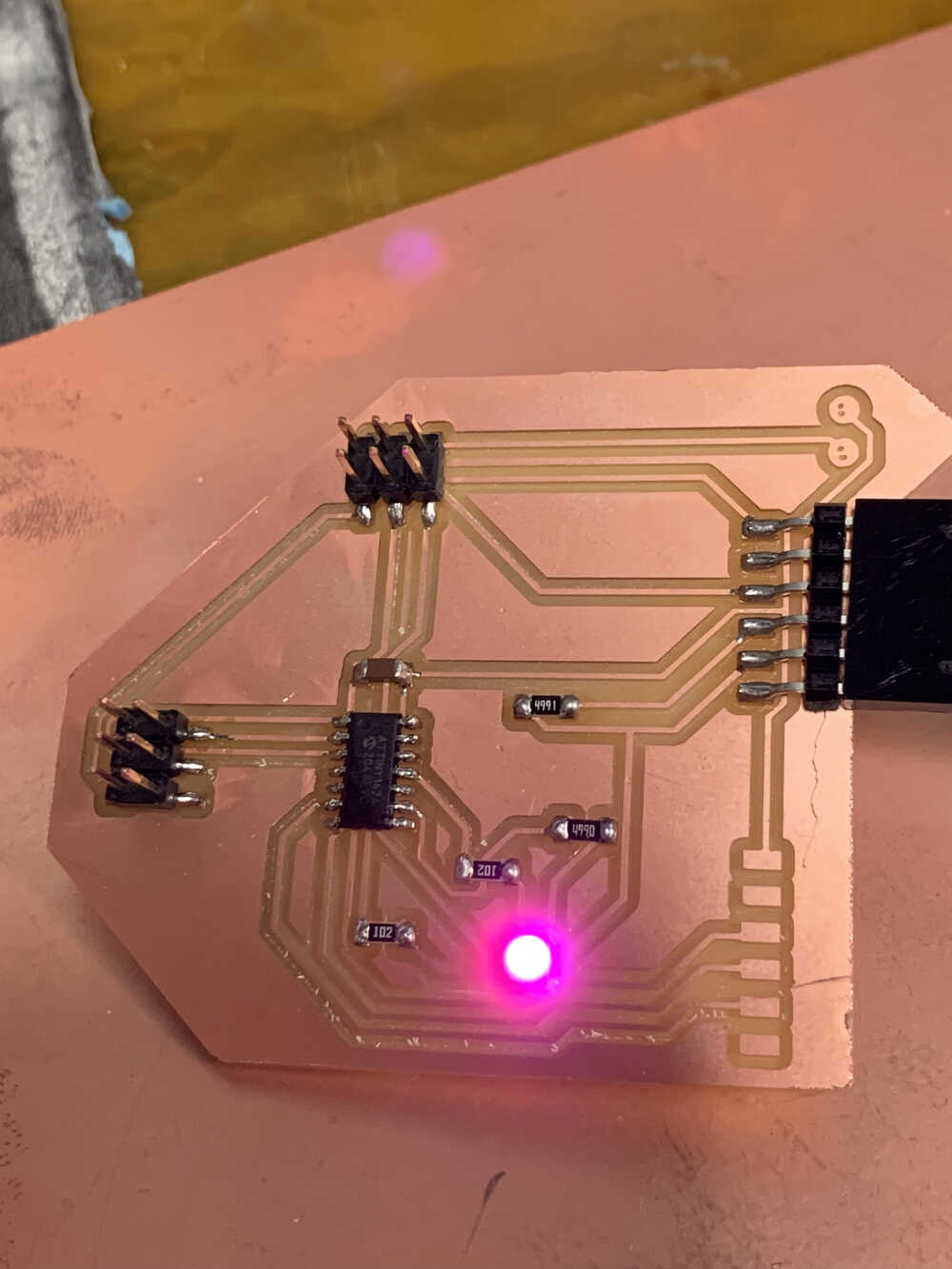
After some experimentation, we were able to get the RGB LED to light up with different colors:
Finally, it was time to connect some motors and try to control them. We did not attend to the ESC motor this time around unfortuantely, but featured it heavily in the final project. However, we were able to power a single servo and have it move around. To program servo motors, one needs to include the "Servo.h" library, and then create a Servo object and attach it to the appropriate pin. To control it, one needs to call the "write" method on the servo object created with the Servo class. Sample code for that include this for loop:
            for (pos = 0; pos <= 180; pos += 1) {  // goes from 0 degrees to 180 degrees
                myservo.write(pos);  // tell servo to go to position in variable 'pos'
                delay(15);  // waits 15ms for the servo to reach the position
              }
We can see the results in action below!