Laser cutting, Vinyl cutting, Git
Laser Cutting
Laser Parameters Characterization
This week, in addition to learning how to build my class website using git, I got to use the laser and vinyl cutters as part of the computer-controlled cutting module of the class. As a group, we started with the group assignment which was to characterize the parameters of the lasercutter and determine the optimal settings (focus, power, speed, rate, and kerf
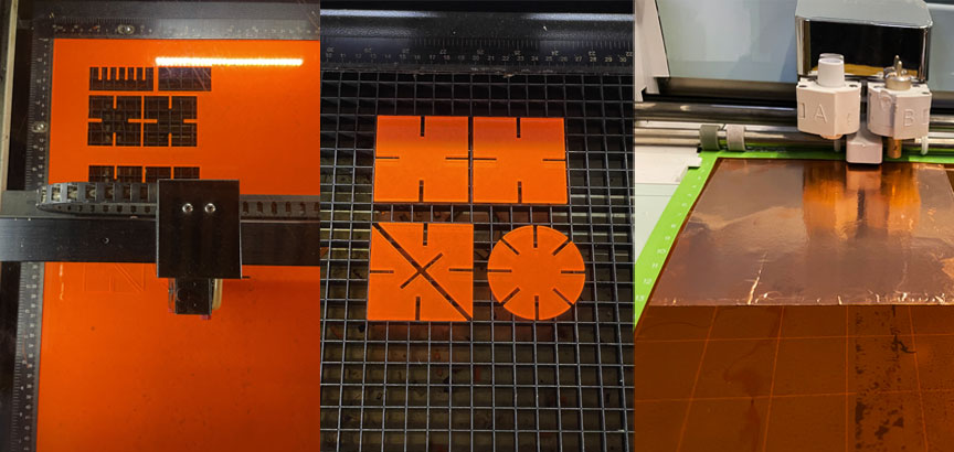
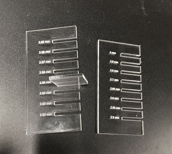
The photo on the left below shows the results of our attempt to find the base parameters for cutting a 3-mm acrylic substrate (our material of choice). After focusing, we fixed the power of the GCC laser cutter to 100% and varied the speed for 5 speed percentages with an increment of 1. As a result, we have determined that the following parameters are optimal for cutting a 3mm acrylic sheet with the GCC laser cutter at CBA: (Power:100, Speed: 1%, PPI: 400) Additionally, we needed to calculate the kerf, which is the amount of the material the laser burns away as it cuts through. This is especially important for cutting joints, as a snug fit would be critical. As seen in the photo on the right, we designed a simple kerf tool with a range of cuts with a 0.01mm difference. The experimental results show a kerf that equals 0.15 mm. This kerf measurement was noted down so that we can account for it in our individual assignments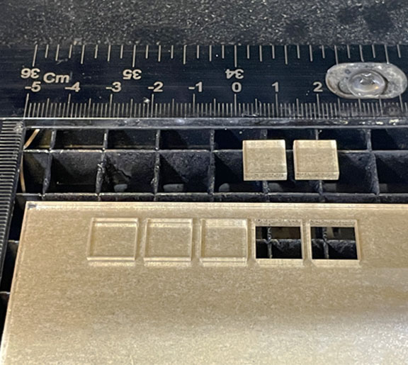
Parametric Design
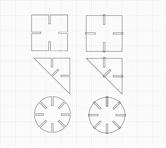
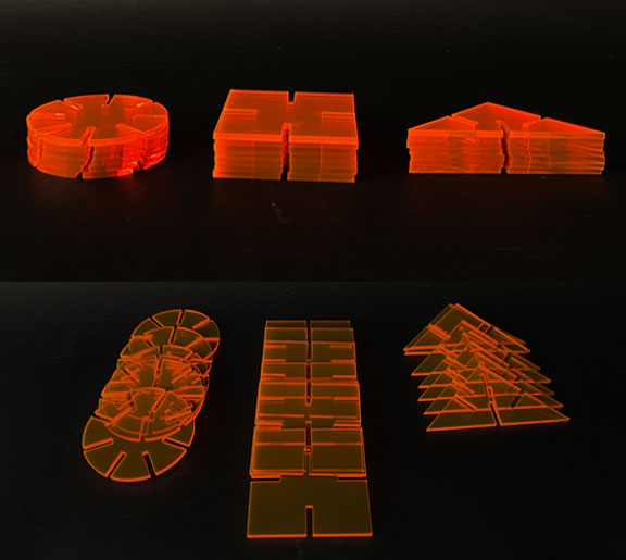
For the parametric design exercise, I decided to re-draw geometric designs inspired by a vintage interlocking construction set called Play Plax. These geometric designs will then act as the building blocks for the construction kit I plan to build
Construction Kit
The image on the left shows the building blocks of my construction kit. I decided to go with an acrylic with neon color (Electric Orange) that we had in the lab. Interestingly, when I measured the kerf again before this test (whoch was the day after the first charztraization), I found out that the kerf changed. I am assuing the focus and laser bed height would be the only paramter that changed. Thus, I went ahead and updated my desing with the new kerf (0.35 mm) before cutting. I wanted to do more shapes and mutiple colors, however, I was limited this week by the amount of hours allocated for each student. I plan to cut mutiple colors and more complex units (living hinges) next week and add them to my kit
Construction Kit
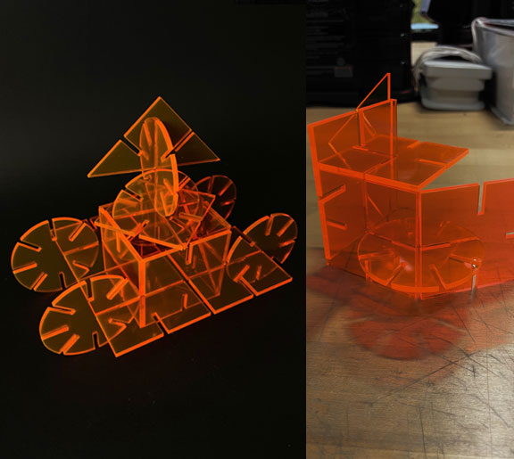
The photos on the left shows some of the fun constructions that can be done using the built construction kit
Vinyl Cutting
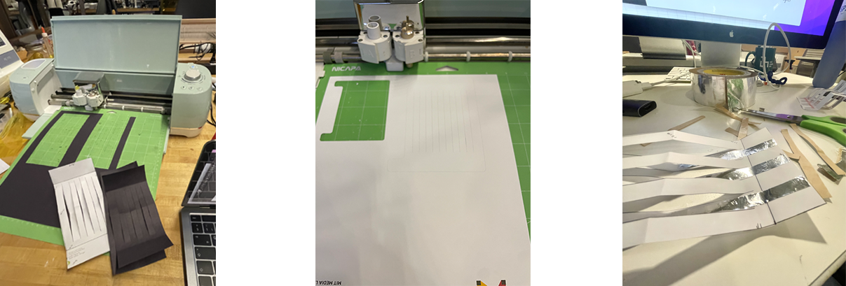
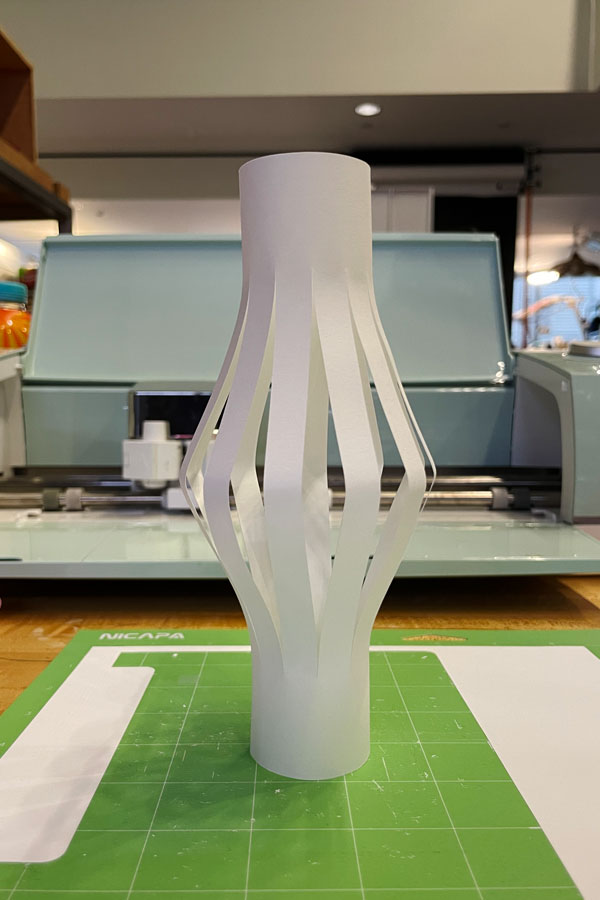
For vinyl cutting, I wanted to explore three-dimensional constructions, which meant exploring Kirgami structures as they involve cutting, and folding flat sheets of paper into three-dimensional forms. As shown in the photos below, I started with plain papers of different thicknesses and then explored how they fold in 3D space. Inspired by this Sensing Kirigami paper, I decided to incorporate functional elemnts with the paper to make sensing elements. The most widely used sensing papers in such context are those impregnated with carbon-based materials to enable resistive sensing. However, I decided to exploit Kirgami for capacitive-based sensing means as well. I adopted the squishy button design shown previously in the literature but modified the sensing areas so that the transduction mechanism is based on capacitance change.
Krigiami -Enabled Capacitive Sensor
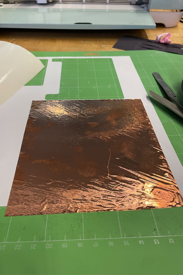
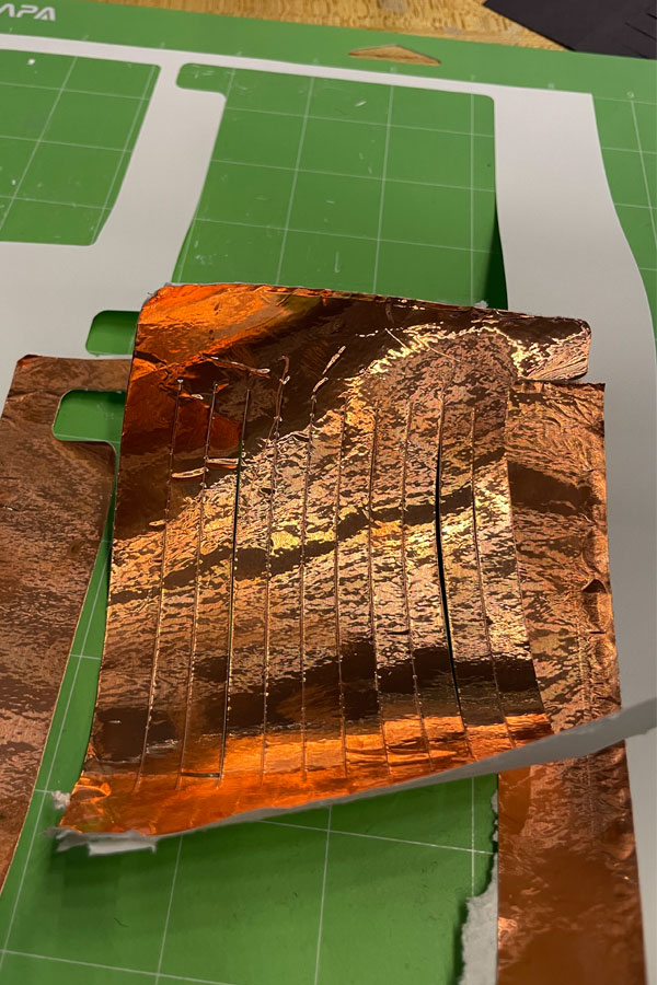
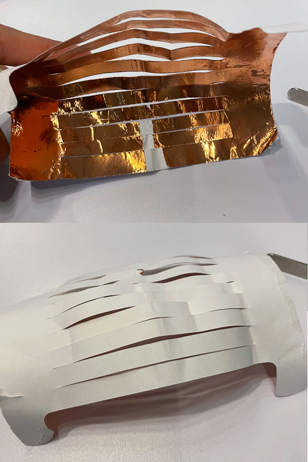
Copper on Paper
To realize the capacitive-based interactive button, I needed to choose appropriate materials that could act as my conductive and insulating elements. To begin with, I tried copper on thick paper first. When I tested the Kirigami button structure on plain paper alone, it was perfectly fine. However, when I laminated the copper tape on top of it to selectively metalize some areas, the structure became weaker and prone to wear off due to the mechanical mismatch between the two papers as shown in the photos are below
Krigiami -Enabled Capacitive Sensor
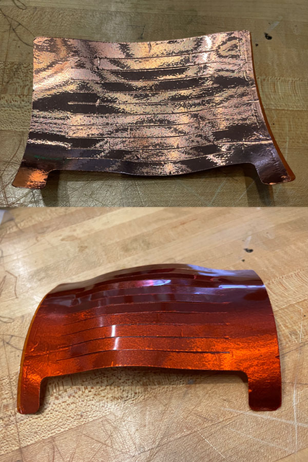
Copper on Polyimide
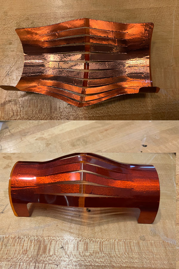
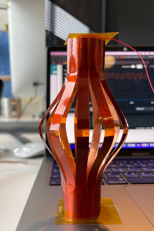
I replaced the paper substrate with 0.125 mm-thick polyamide sheet to solve this issue. Polyamide is an excellent insulator and is more sturdy than plain paper. The photos below show the final folded interactive button structure
Sensor Strcutre: To achieve capacitive sensing, I constructed two sets of comb-like electrodes, each acting as one metallic plate of my capacitor. As I push the button downwards, the spacing between the finger of the comb-like structure will decrease, which increases the capacitance btween the two electrodes
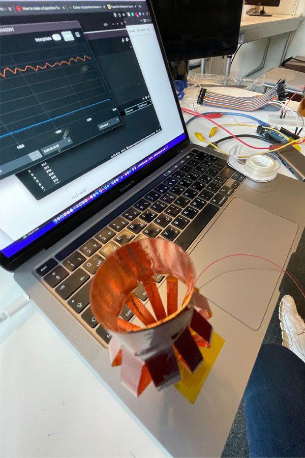
Kirigami Sensor in Action
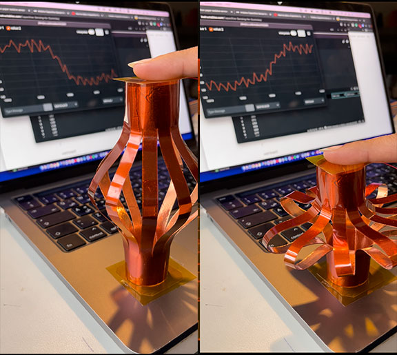
In order to test the output, I used the Capacitive Sensing Library of Arduino and configured it with my developed sensor. The photos and the video below show the raw output of the capacitive sensor from the serial monitor as I press/release the Kirigami interactive button
Sensor in Action
The best part about this construction is that the insulating and conductive elements were both cut/patterned/folded using one underappreciated machine, the vinyl cutter. In the future, I would like to explore more structures/sensing mechanisms and actuators to complete the feedback loop in a meaningful manner!