Tools: MODS, EDGB, PCB Milling (SRM-20), Soldering, Arduino IDE, Blynk
Networking and Communications
This week's assignment was to design, build, and connect wired or wireless nodes. So far, my previous weeks' boards are all based on SAMD11/SAMD21. For communication week, I decided to use ESP32, a versatile, low-cost, low-power system on a chip microcontroller with integrated Wi-Fi and dual-mode Bluetooth!
Since my final project is still in progress, I thought it would be a good idea to make an ESP32 dev board that I can utilize in the coming weeks while building my final project boards. I came across this nice Barduino project designed by Eduardo Chamorro Martin in FabLab Barcelona. It is essentially an ESP32 fab-compatible development board to help the students develop their work on top of it. After cross-checking the components we have in the shop, I decided to go with Barduino 2.0 which is an FTDI version
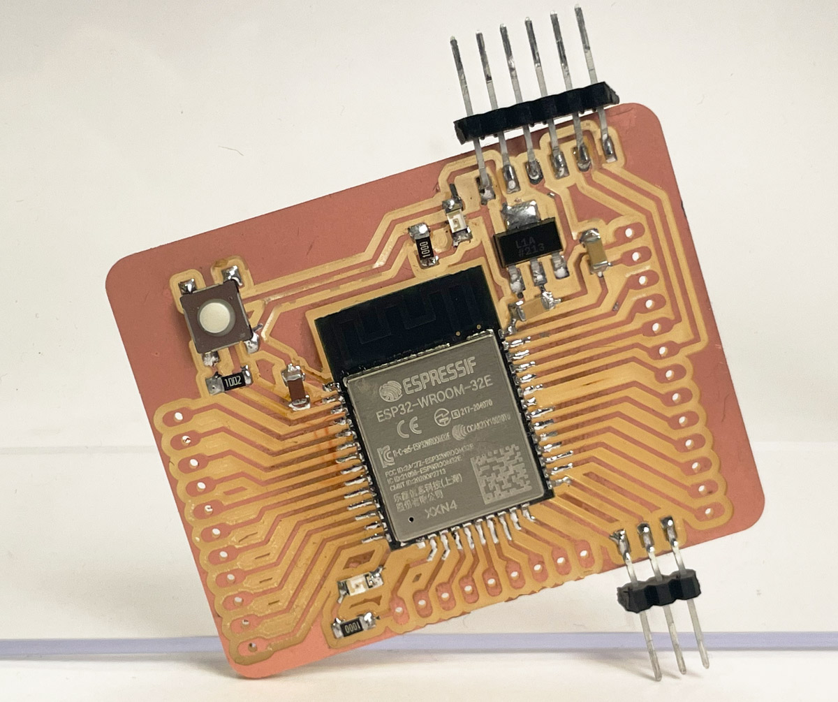
The board has the following components, which are all available in the inventory :
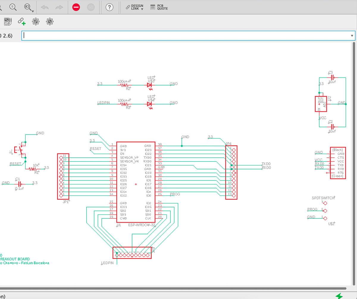
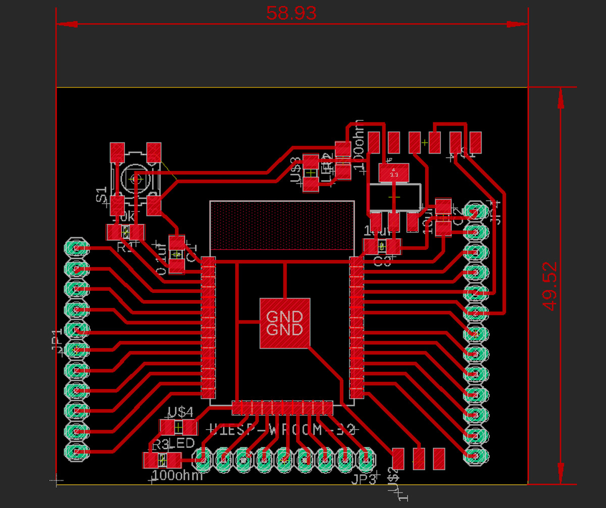
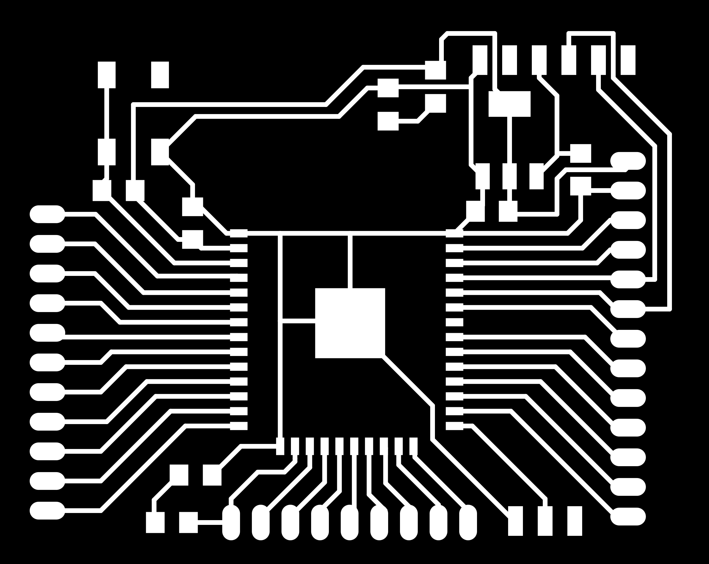
The board schematic, layout, MODS fabbable pngs are shown below
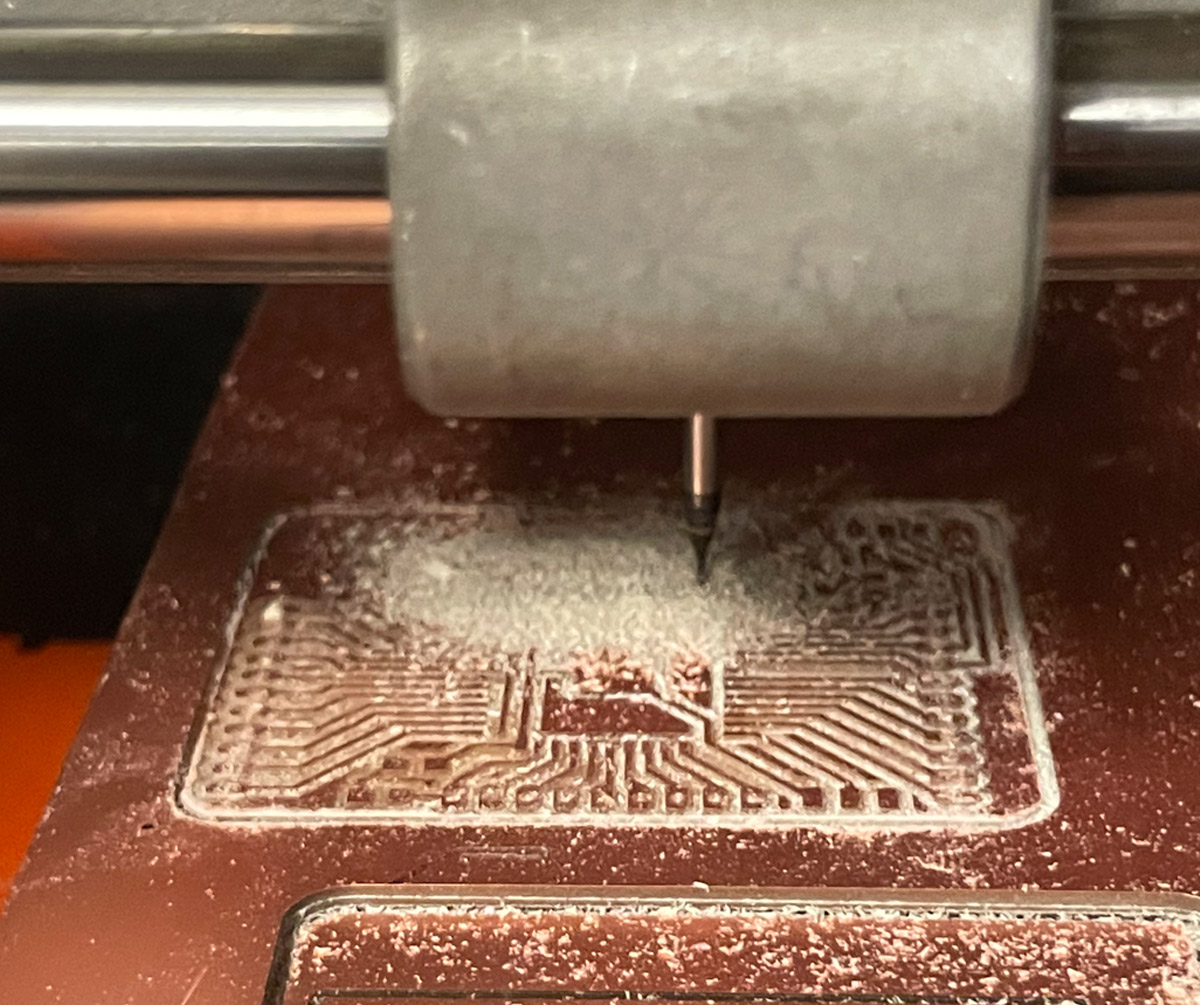
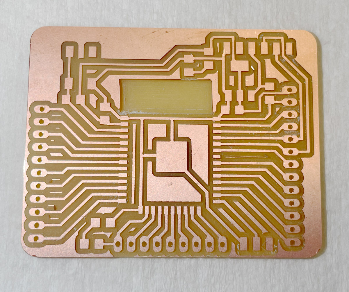
Board Milling and Soldering !
The milling went quite well. It was the first time I tried copper milling to remove the copper underneath the antenna, and that was a sucess too. One issue I noticed was that although I calibrated the z as usual, the mills were a better depper than usual. I could only account for this by offsetting the z level a little higher (.2 mm more) than the "zero" before I started the mill.
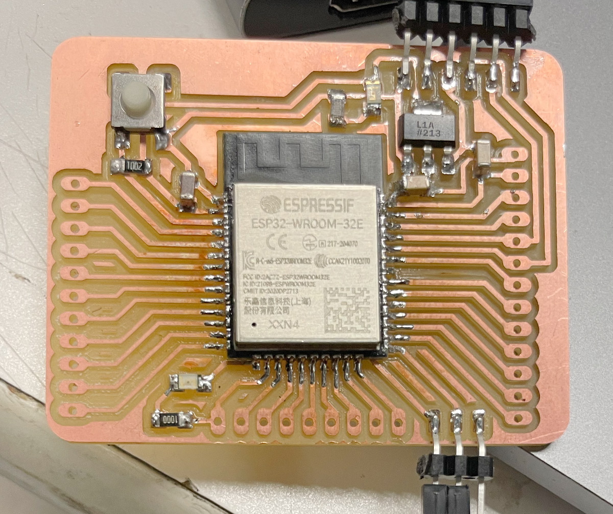
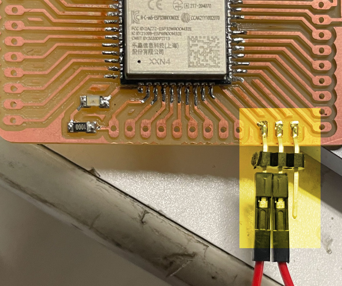
Soldering the components was also fine, except for the esp32 WROOM module itself. So far, it had the smallest pads I used so far so it was a bit tricky. The first time I attempted the soldering, the chip was misaligned, so I needed to remove it with hot air and solder again. Also, since the slide switches were surprisingly out of stock at the CBA shop, I replaced the switch pads with male pin headers so that I can insert a jumper wire when I want to use the switch and change from excution to programming modes. That was easy and good enough of a solution, highlighted in yellow below.
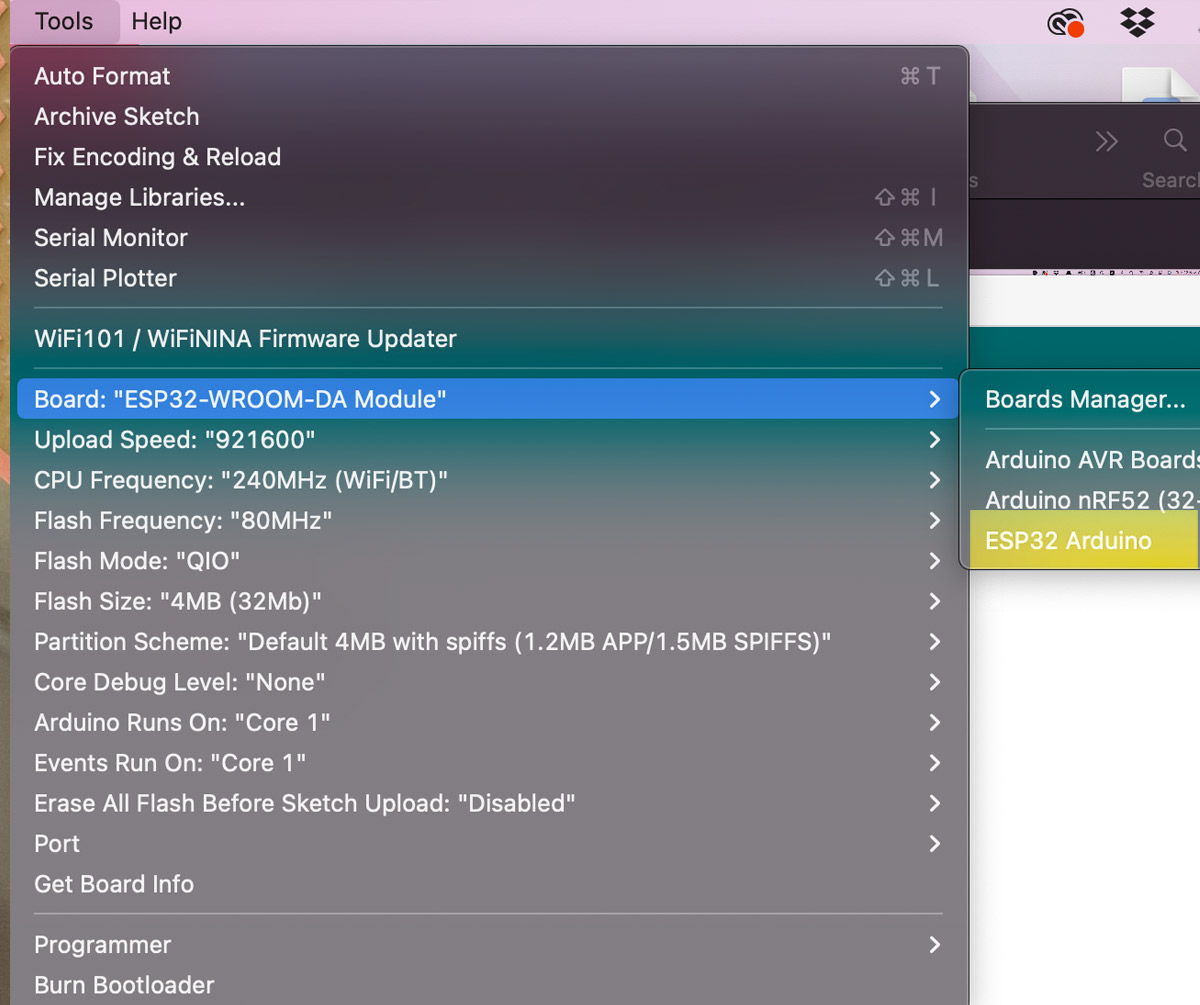
ESP32 and Arduino IDE
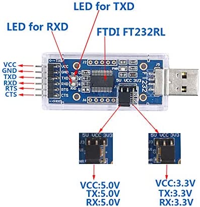
In order to start using the ESP32 with Arduino IDE, I used this USB to TTL Serial Adapter with FTDI (FT232RL) chip. I also downloaded installed the Espressif ESP 32 library from here .
I made sure that the FTDI pins in the adapter is connected proeprly to FTDI pins on the board. When uploadingt the code ,thhe tactile switch is needed for RESET, the slide switch is needed to change modes between program and execution modes.
ESP32 Blink
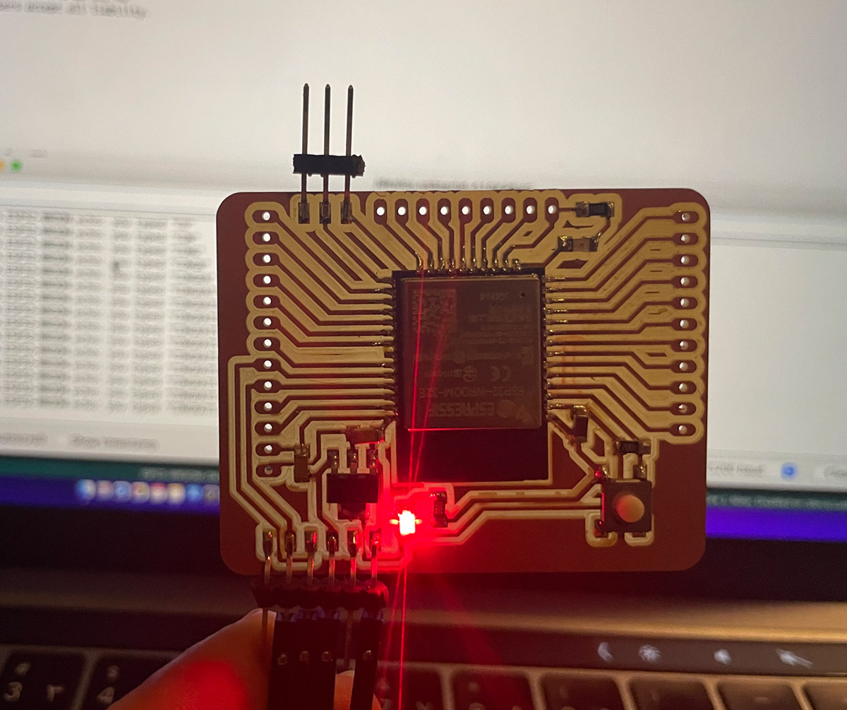
To test if my board is functioning well, I first programmed it with the basic blink code. I connected the jumper wire to switch the board to (Program), and ran the code. I pressed the tactile button (Reset) when Arduino shows “Connecting....” during the uploading process
After it was programmed successfully, I removed the jumper wire to switch the esp32 to "Run" mode and pressed the tactile reset button. The led connected stated, blinking as expected.
ESP32 Echo
I also ran Neil's hello.ESP32-WROOM.echo using the Arduino IDE and was succdull. In light of my home conuntry national team's (KSA) historic win against Argentina in the FIFA world cup today, I decided to celebrate by typing "Congrats KSA!!"
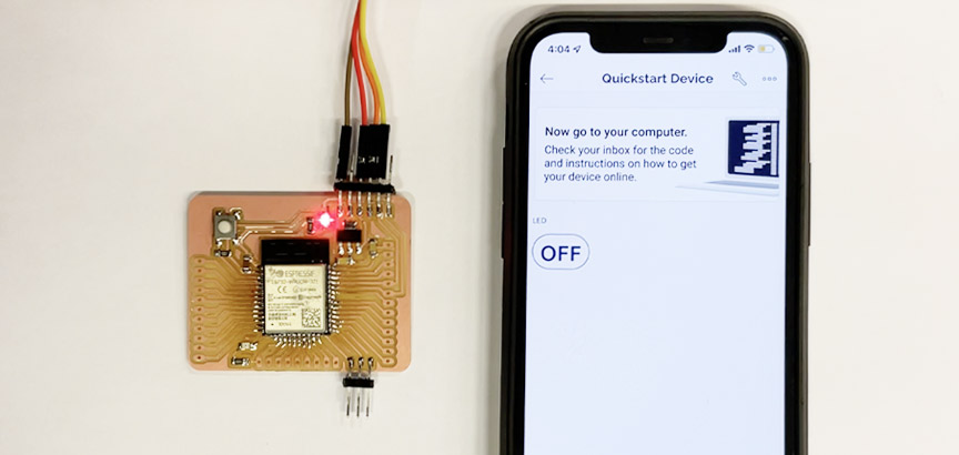
ESP32 and Blynk App Communication
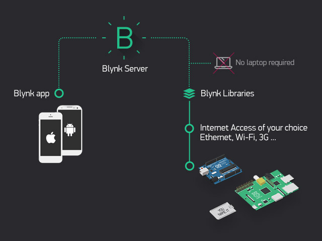
To control the board wirelessly, I decided to use the Blynk app from Blynk IoT IoT, which is compatible with iOS or Android smartphones and is used to control Arduino, Raspberry Pi, and NodeMCU via the Internet. In order to start using the Blynk App with my board, I downloaded and installed the Blynk Library in Arduino IDE .
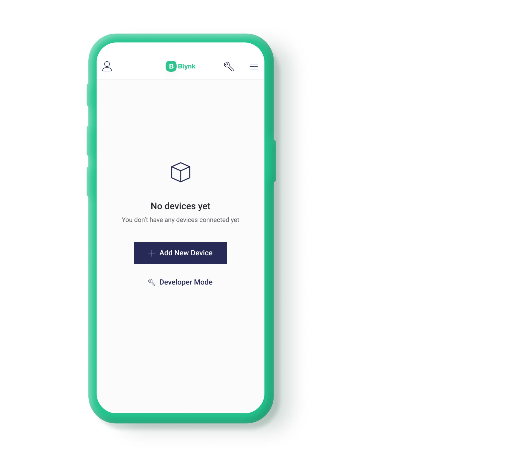
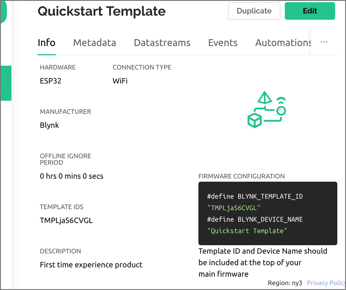
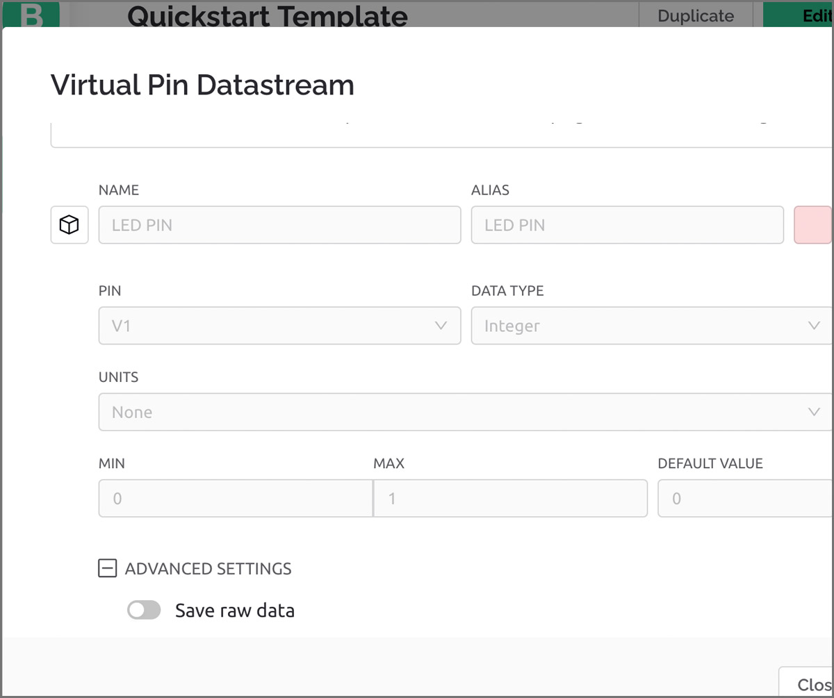
Using their web dashboard, I added a new device which generated a unique template and AuthToken IDS that I can use while programming my Esp32 board and to configure it as a WiFi device. I have also added a datastream which will act as a virtual pin (V1), which is basically a channel that is going to be used to send data between the device and Blynk.Cloud. In my case, I configured it as the following:
Then I needed to add a switch/button widget that would correspond to that virtual pin. Since I want to control the LED (ON/OFF), I chose a button widget. In my code, virtual pin V1 was assigned to the GPIO 13 pin which is connected to and LED pin in my physical baord. For reference, Blynk has nice extensive documentation that can be found here .
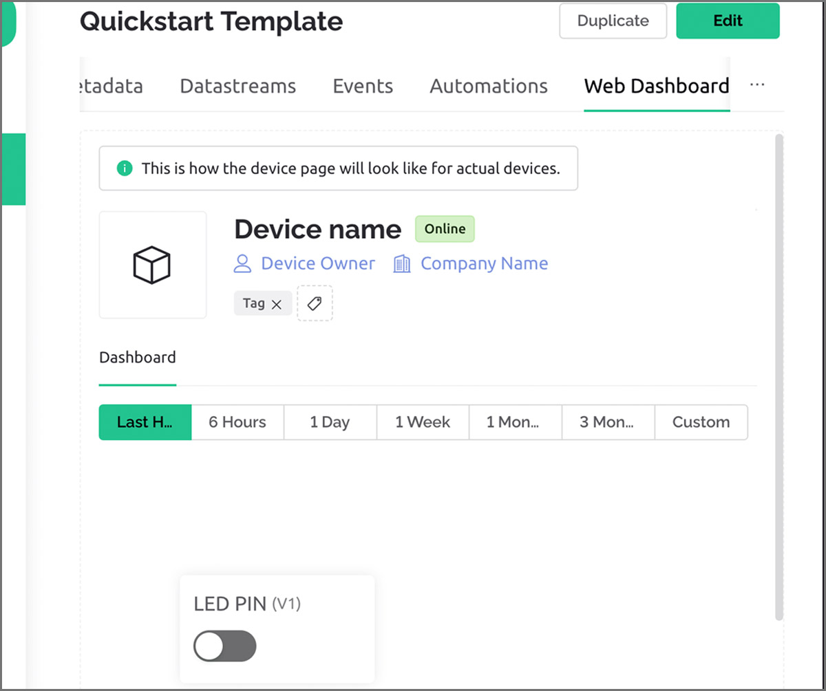
After programming the board with the new Bynk code,switing the baord to Run mode, pressing reset button, I was able to control the LED on my Barduino 2.0 through my phone and the Blynk App as demonstrated in the video below!