Tools: Smooth-on, PDMS, Formlab 3, 3-axis milling
Proprioceptive Soft Robot (GRACE)
This week is molding and casting week. The assignment was to design a mold around the stock and tooling we will be using, mill it (rough cut + three-axis finish cut), and use it to cast parts! Since Ozgun and I have a shared interest in soft and stretchable structures, we decided to collaborate this week to realize a soft robot that is augmented with sending element to enable proprioception!
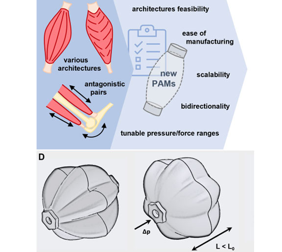
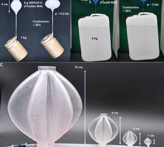
We got inspired by this article recently published article in Science Robotics, where researchers developed a novel type of pleated pneumatic artificial muscle. The fabrication method they utilized was 3D printing the actuators, which allowed a wide variety of sizes. They have named the results GeometRy-based Actuators that Contract and Elongate (GRACE). The GRACEs consist of a single-material pleated membrane and do not need any strain-limiting elements. They can contract and extend by design, as described by a mathematical model, and can be realized at different dimensional scales and with different materials and mechanical performances, enabling a wide range of lifelike movements.
Although 3D printing seems to be one of the easiest methods fot fabricating such structures, we decided to challenge ourselves this week by replicating the structure using a two-part molding approach! Sometimes 3D printing, such as FDM and laser-based SLA consumes more time due to the serial nature of the process. However, molding and casting are not usually an issue since after milling the mold for one time, casting multiple elements will only be limited to the curing time of the material. Thus, each method has different pros and cons depending on the use and resource availability.
CAD Model
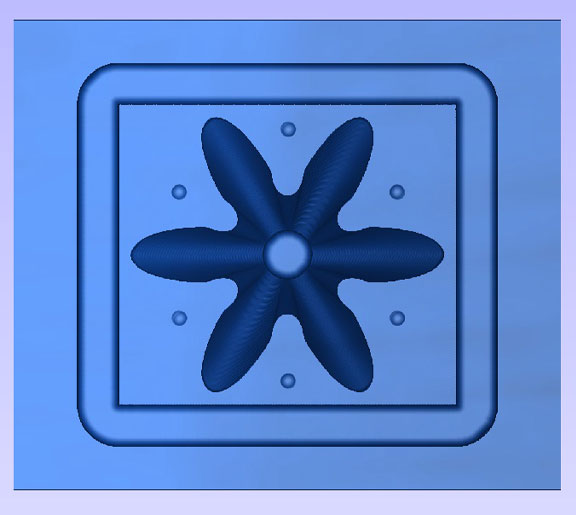
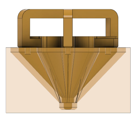
For generating the CAD design, we used Adobe illustrator for the initial 2D sketch and fusion 360 to render the 3D model. On the right, a top view of the bottom part of the mold is shown
CAD Model
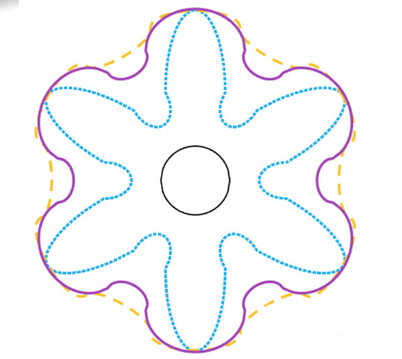
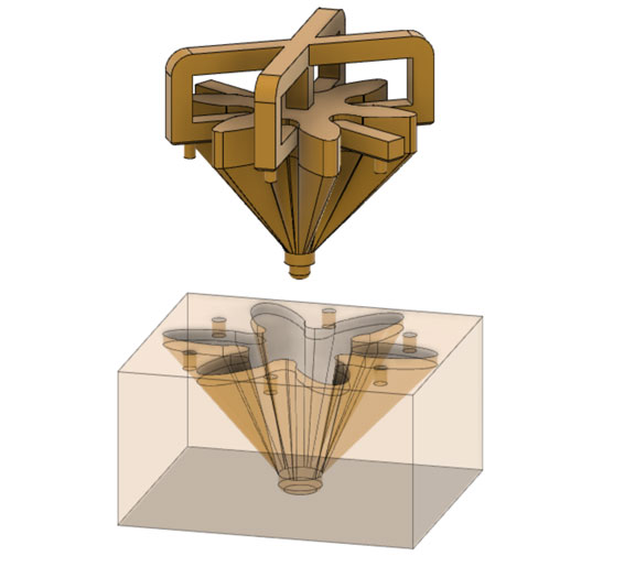
As shown in the left photo below, we started with the 2D sketches provided on the referenced paper as a starting point. It is worth mentioning that the paper explored multiple geometries and dimentions; we decided to go with the one that they mentioned performed better in contraction. This structure has narrow ellipses and deep pleats, which can largely expand when the GRACE is inflated.
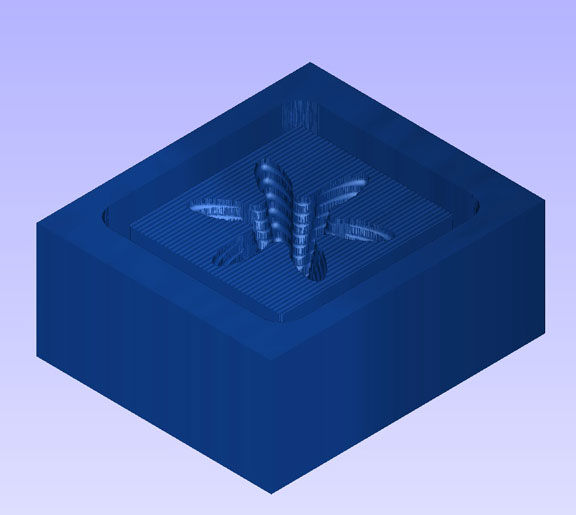
Following the 2D sketch, Fusion 360 was used to generate the extruded 3D model. Since we are directly milling our negative mold, as seen below, our model consists of two parts. One is the bottom part which will form the outer structure of GRACE. The second is the top part which will form the inner structure of GRACE, ensuring that it will be a hollow shell.
Tool Path Generation
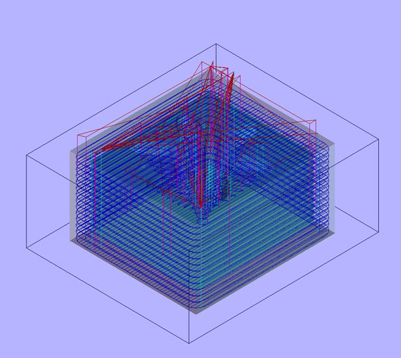
In order to generate the tool path for 3-axis milling, we used Vectric 3D cut software.
Tool Path Generation
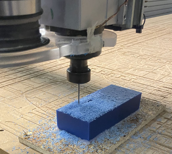
Following the guide provided by John and Tom from CBA , we were able to generate the tool path file that the 3-axis milling machine will read. Given the time and material limitation we had, we decided to mill the bottom part of the mold, and 3d print the top part of the mold to be inserted. We loaded an STL into the software. We used a .125” ball end mill since it would be more suitable for carving the curved valleys in our model. Our stepovers were 40% of the tool diameter for the roughing toolpath and 10% for the finishing toolpath.

The photos below show the process of milling our wax block using the 3-axis milling tool.
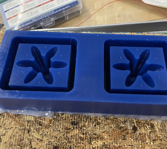
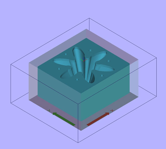
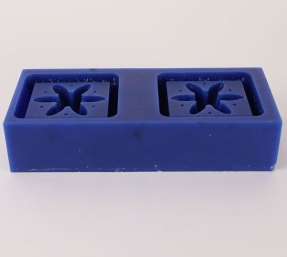
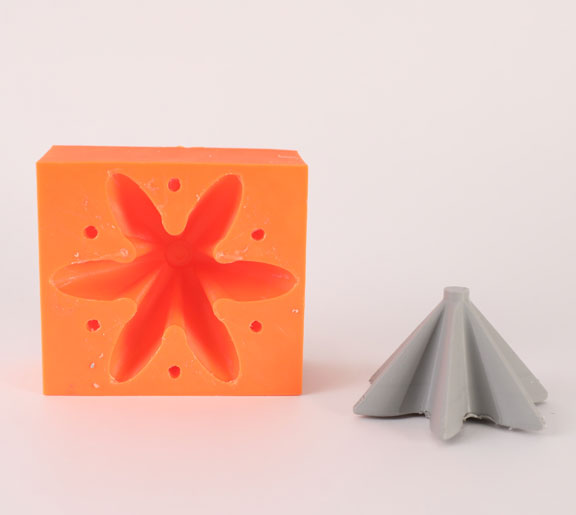
Milled Mold
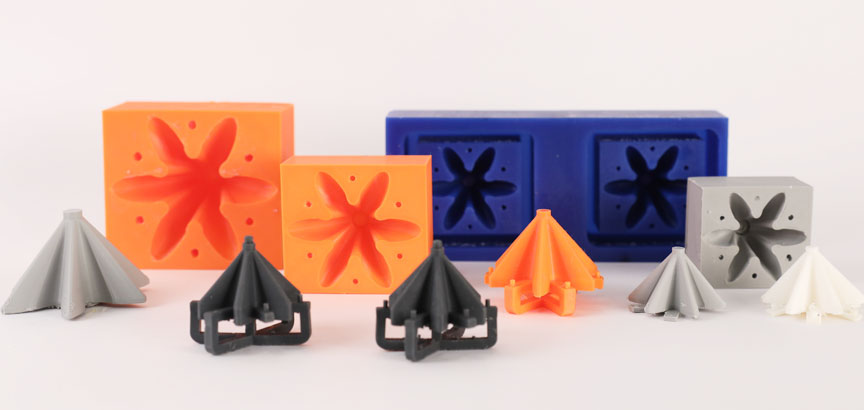
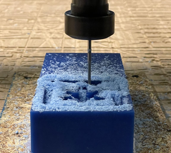
The photo on the right shows the final milled mold. Since we had the space and time, we replicated the structure twice to be able to cast both parts of GRACE in one go. We also applied silicone release agent spray on the mold before casting to ease the demolding process.
Milled Mold
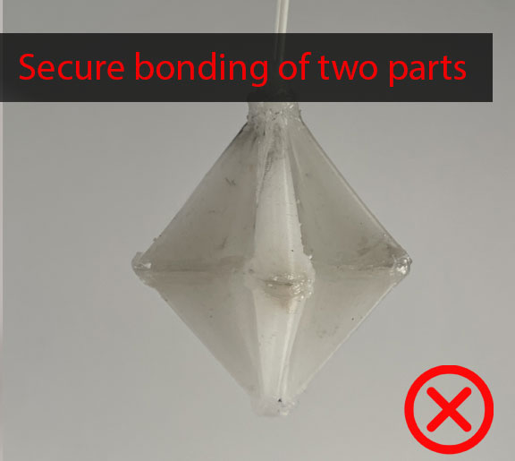
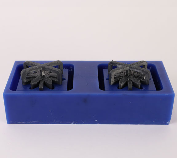
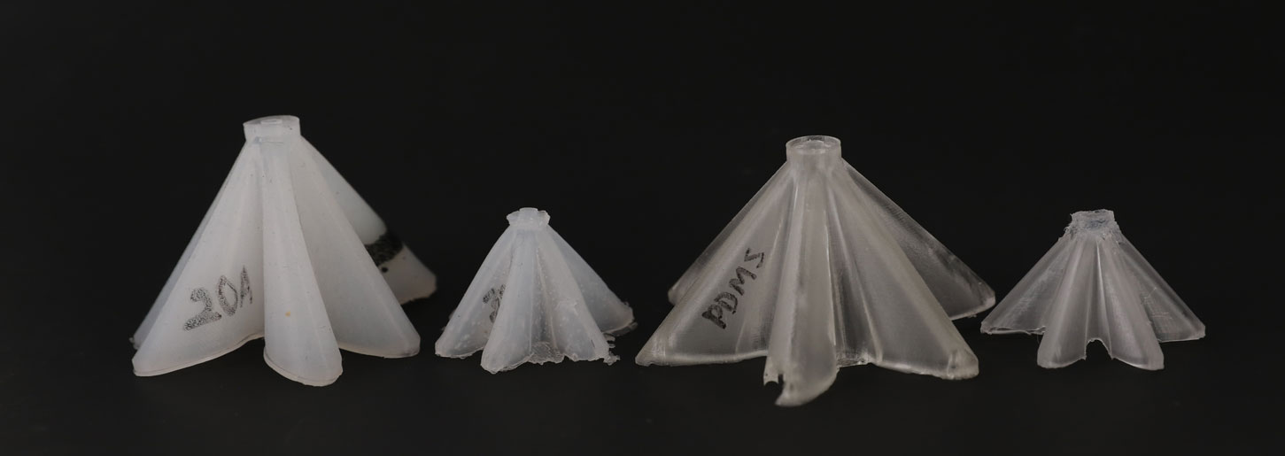
We tried to cast a variety of materials, including PDMS, Smooth-On EcoFlex 20A), 30A and 50A. We used Smooth-On SIL-poxy rubber silicone adhesive to bond the two casted parts together.
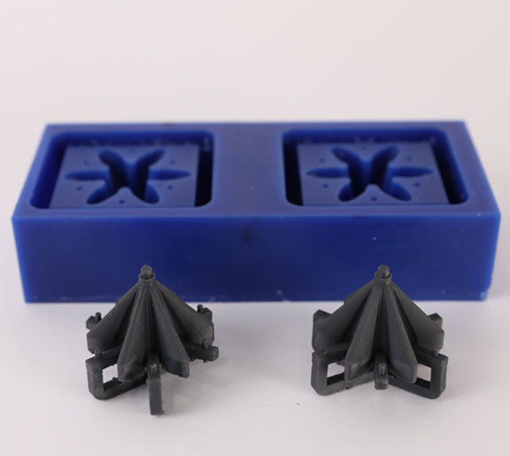
3D Printed Mold
The image on the right shows the 3D printed mold fabricated using Ender 3.
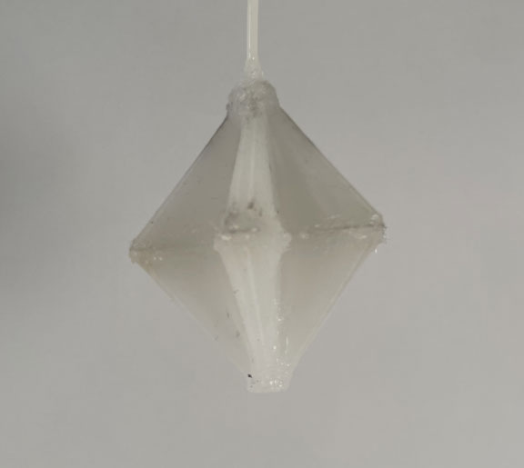
Initial Results
We tried to cast a variety of materials, including PDMS, Smooth-On EcoFlex 20A), 30A and 50A. We used Smooth-On SIL-poxy rubber silicone adhesive to bond the two casted parts together.
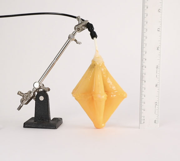
Casted Structure - Testing
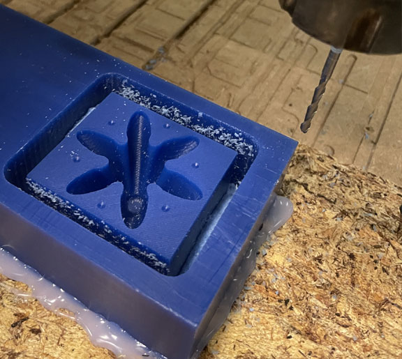
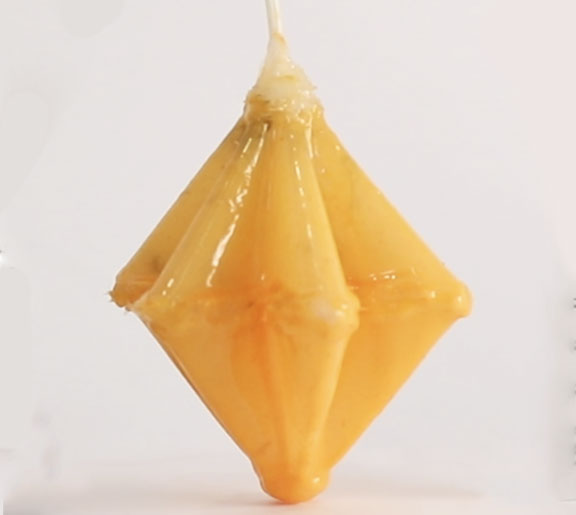
The photo on the right shows an assembled GRACE where we used Smooth-On EcoFlex 30A for casting and Smooth-On SIL-poxy rubber silicone adhesive for bonding the two parts together. We also applied a thin layer of yellow colored smooth-On EcoFlex 30A layer on the outside both for aesthetics and extra sealing.
GRACE in Action
In order to test this first primitive structure, we used FlowIO soft robotics platform developed by Ali Shtarbanov of the MIT Media Lab. the sequential inflation photos are shown below
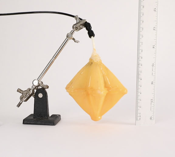
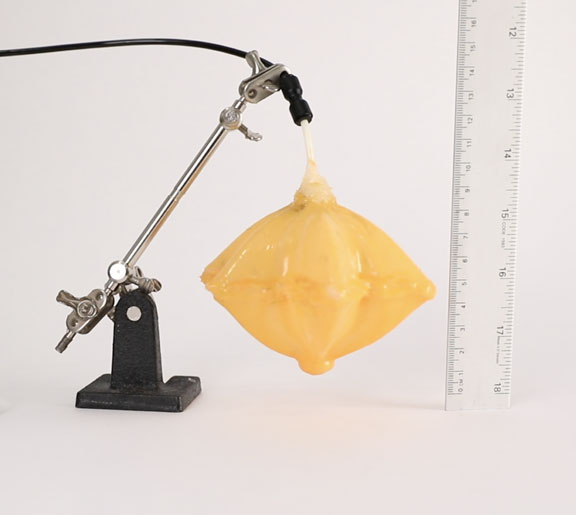
GRACE in Action
A video of the actuation of the soft robot is provided below
Adding Sensing (proprioception)
The future of soft robots is adding both proprioception and perception to the robot so it can smartly react to changing environments. We wanted to add some level of proprioception to our grace structure by embedding a flexible strain sensor.
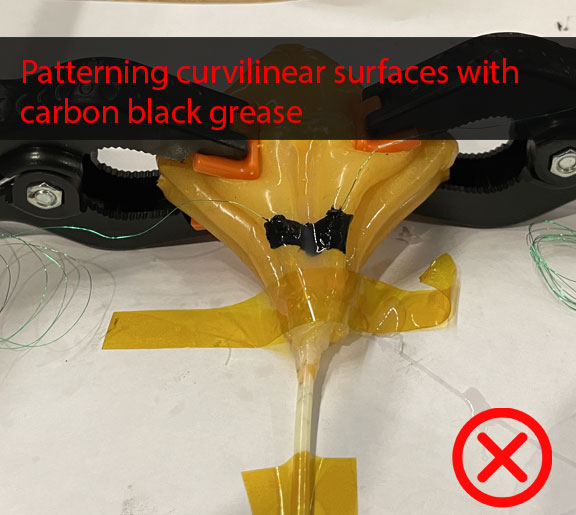
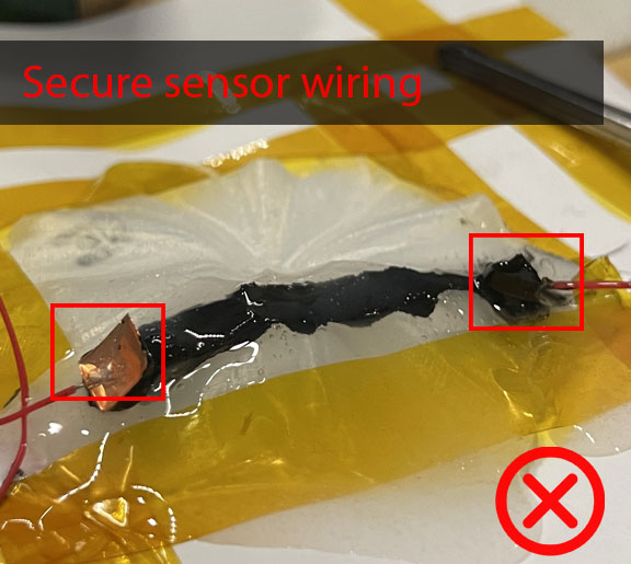
We used carbon conductive grease from MG Chemicals as the main sensing material for resistive -type of sensing. We created a tape senticl mask to make it easier to pattern the great on top. Then we used thin wires to tether the sensor and finally encapsulated it with a thin layer of silicone.
For the sensor readout circuit, We employed a voltage-divider circuit using a commercial reference resistor and our sensor as the unknown resistor. We used Arduino Leonardo as the microcontroller and the Arduino IDE for the serial plotting.
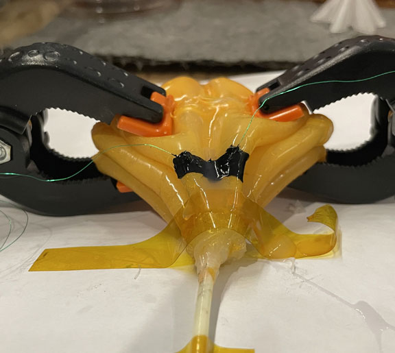

Proprioceptive GRACE !
Below is a video of the sensor output as a result of inflating and deflating the soft robot
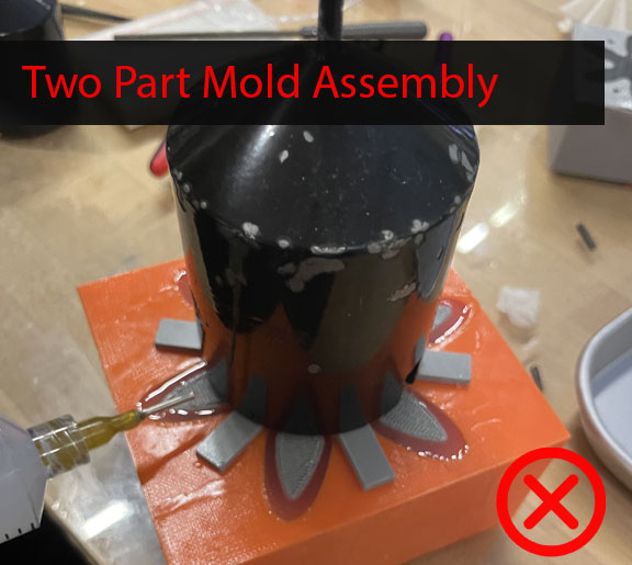
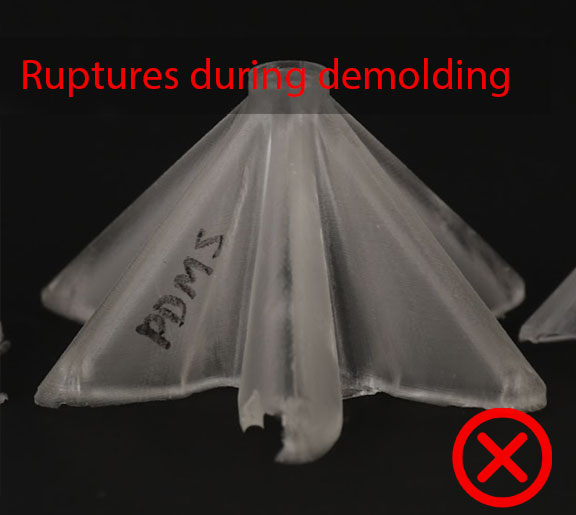
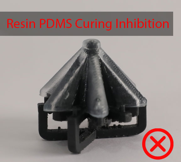
Failures
We experienced many issues and failures during the fabrication process of GRACE. They are summarized as follows: