PROCESS
THIS IS HOW I GOT THERE
↓
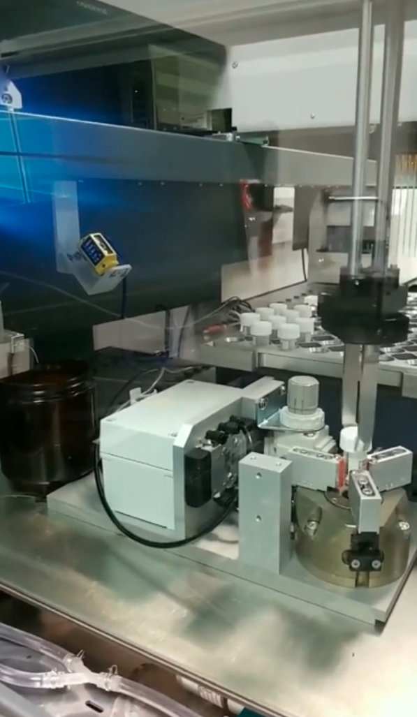
An example from Novartis.
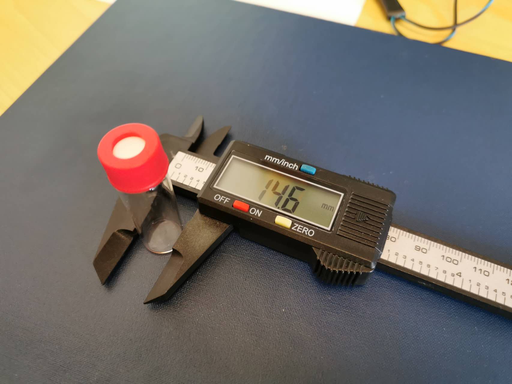
The size of tube we need.
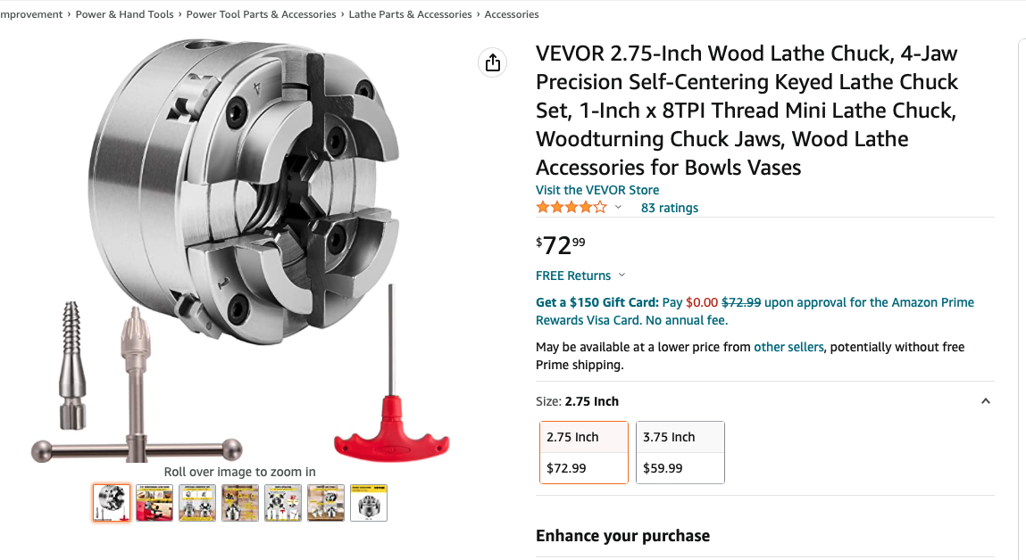
The lathe chuck I ordered.
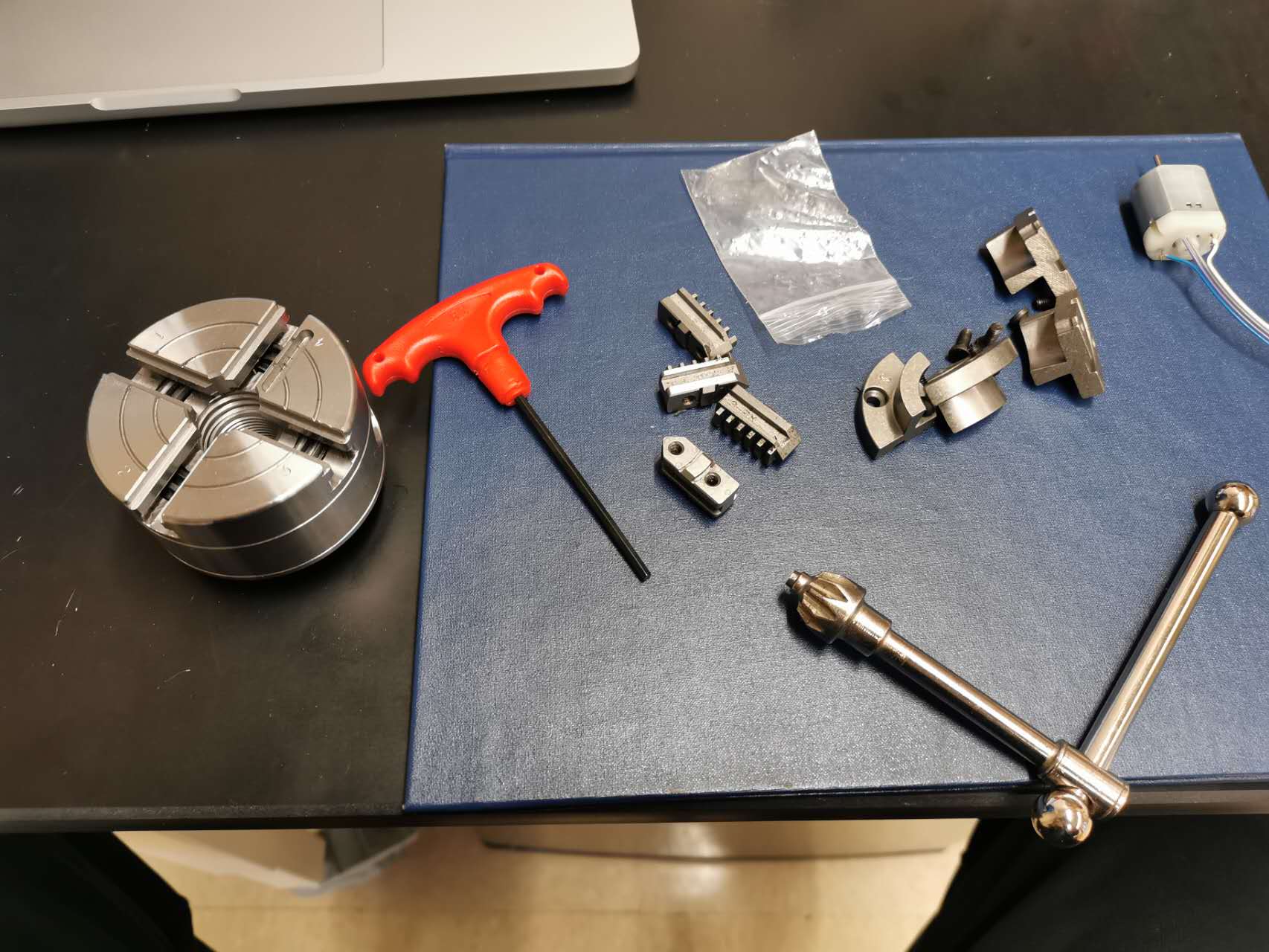
The lathe chuck arrived.
Added foam and it grabs ok.
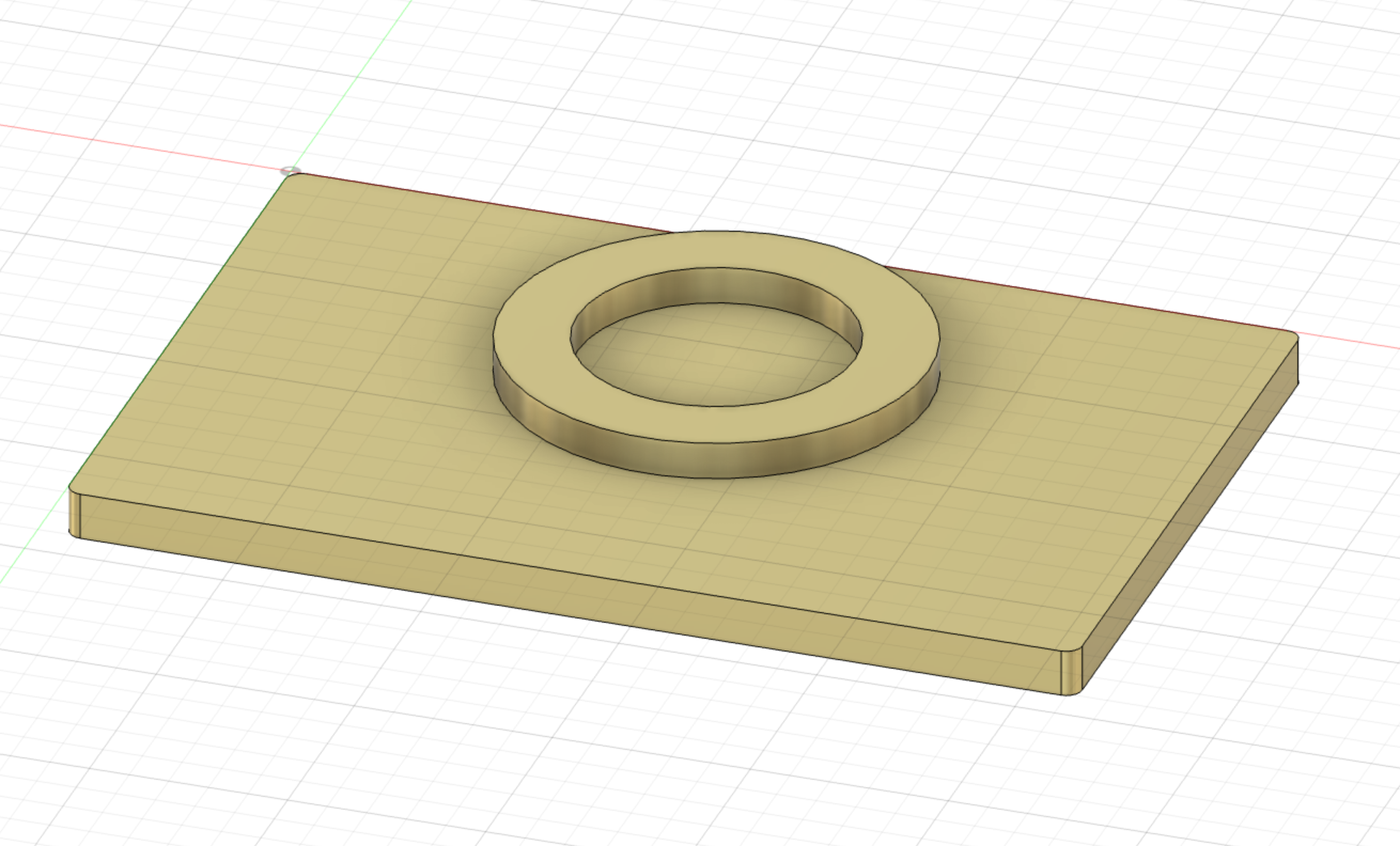
The lathe chuck mount.
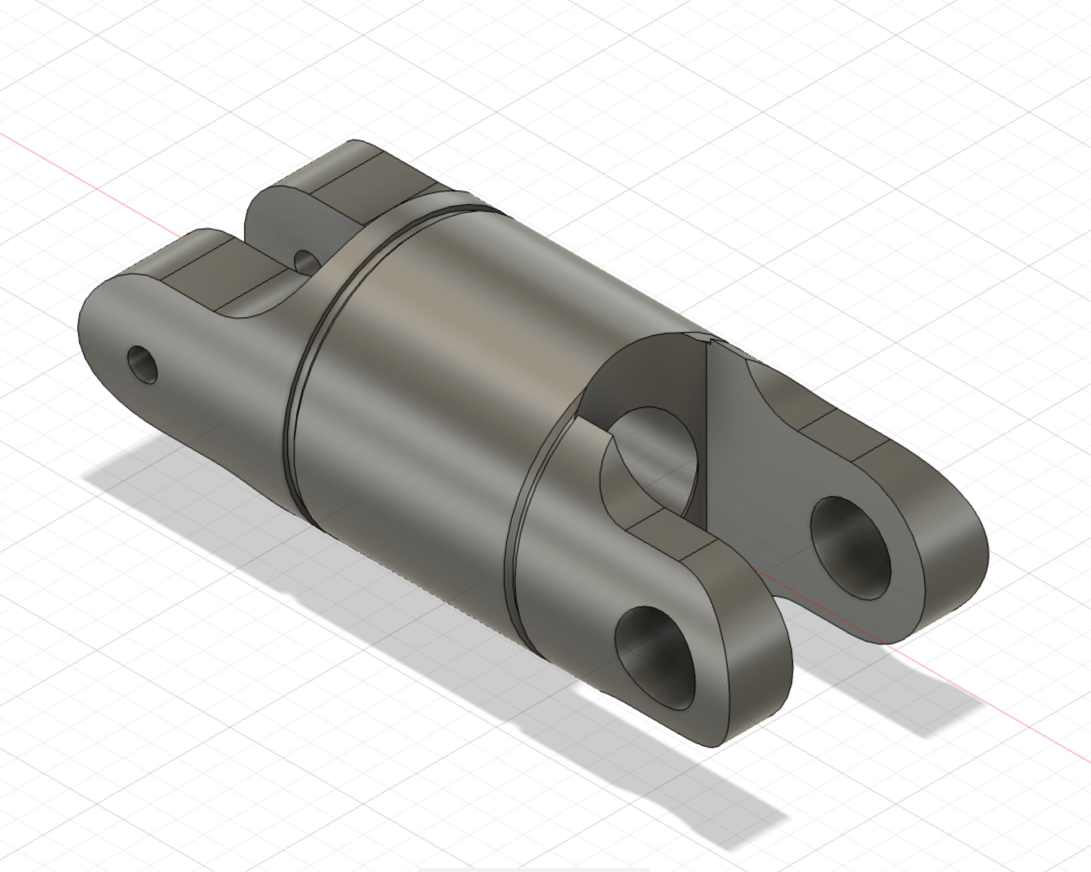
The joint of a geared DC motor and wrench.
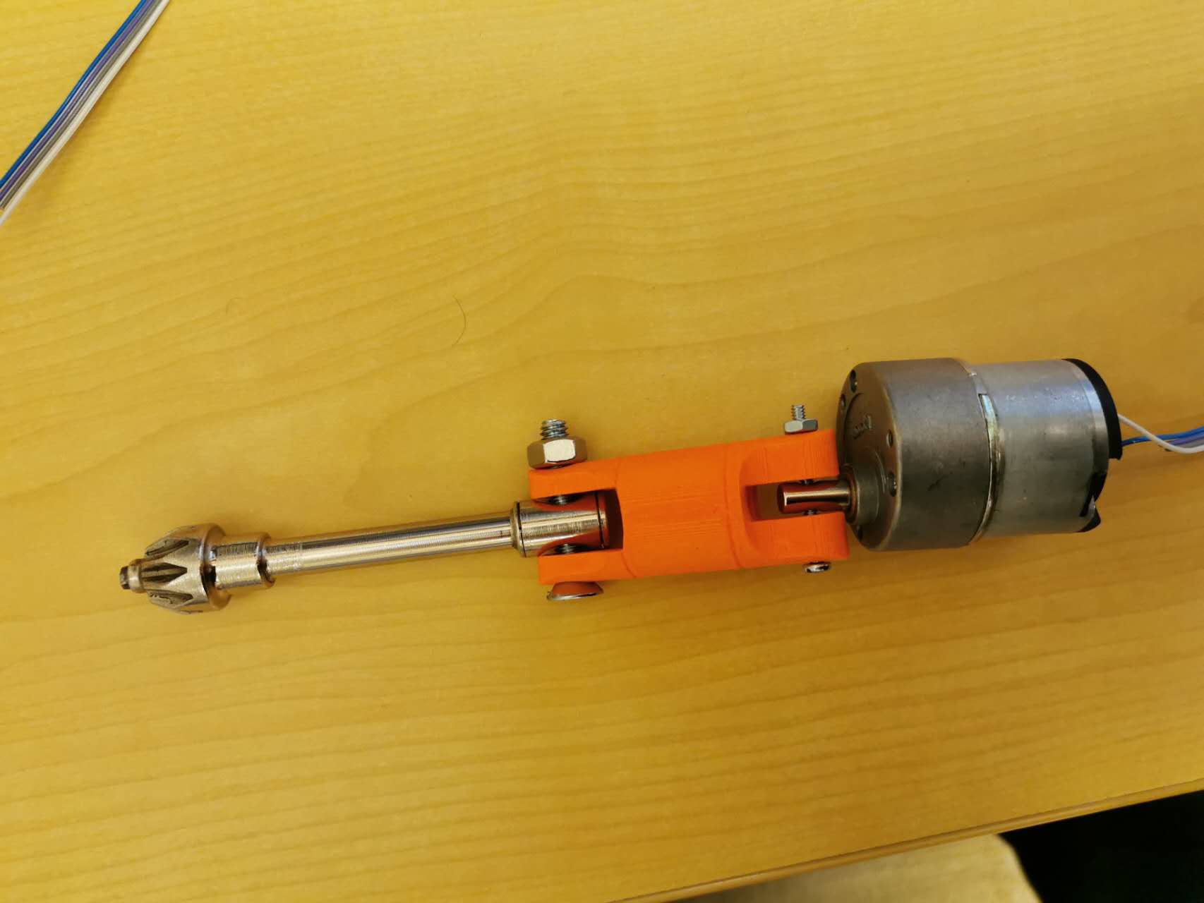
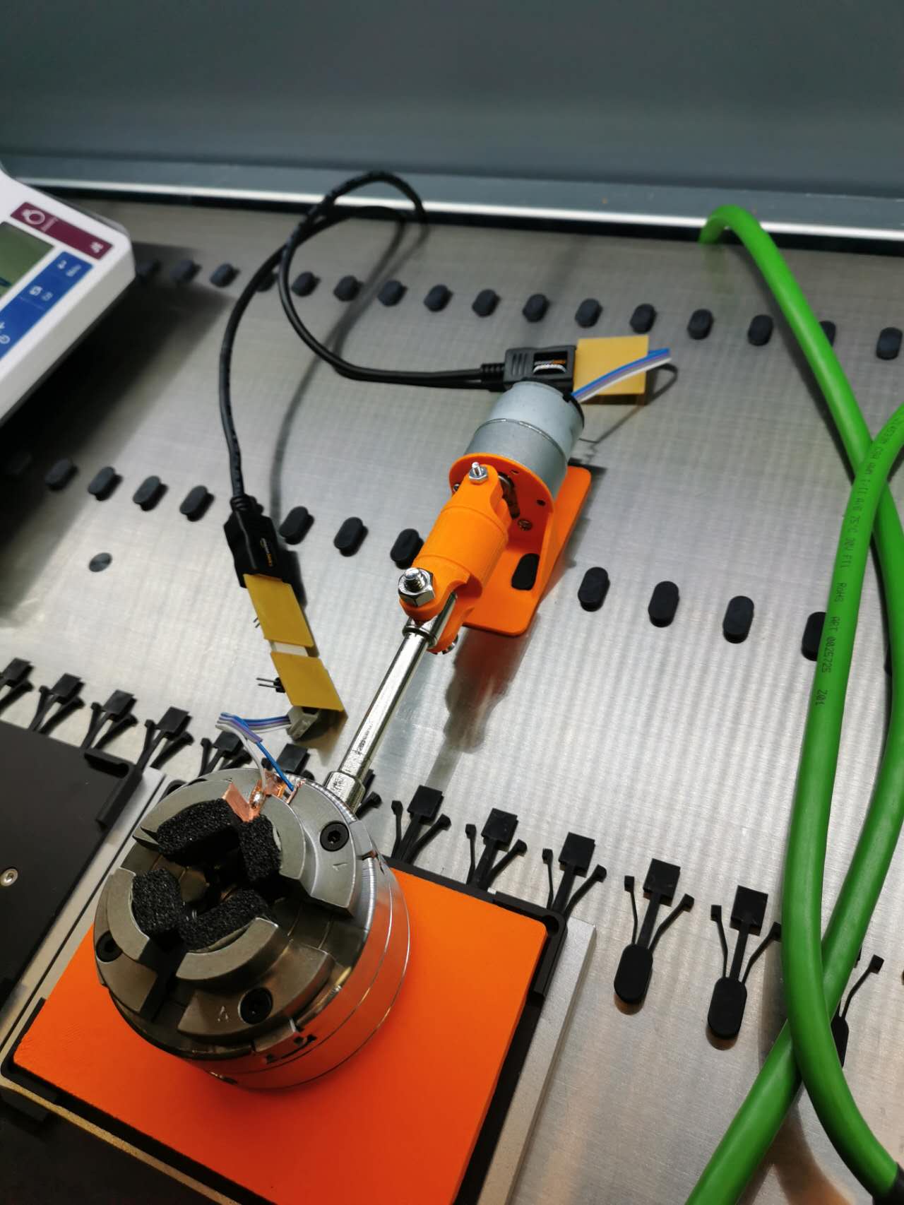
3D printed and connected.
Test the joint.
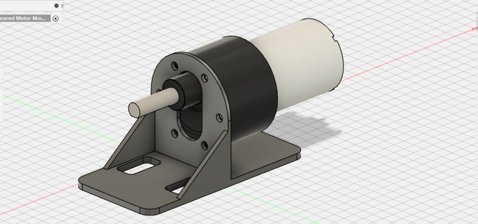
The designed mount for the DC motor.

The designed mount for the DC motor.
Ensmebled together.
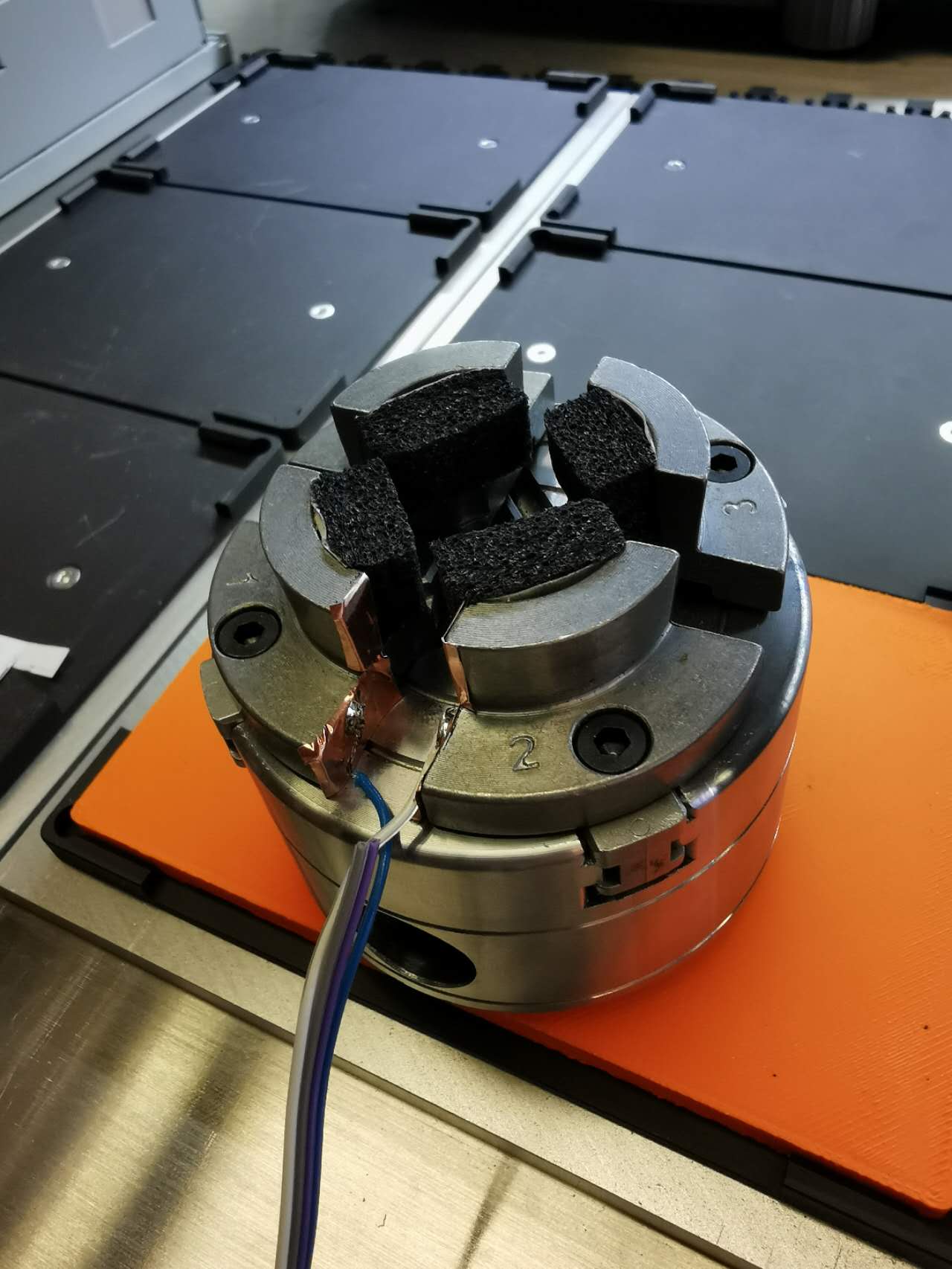
How the copper layer looks like.
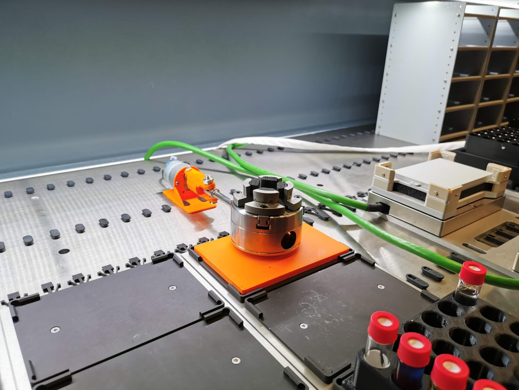
A top-down view after ensmebling.
Demonstration of grab-or-not sensing.
Demonstration of how it works.
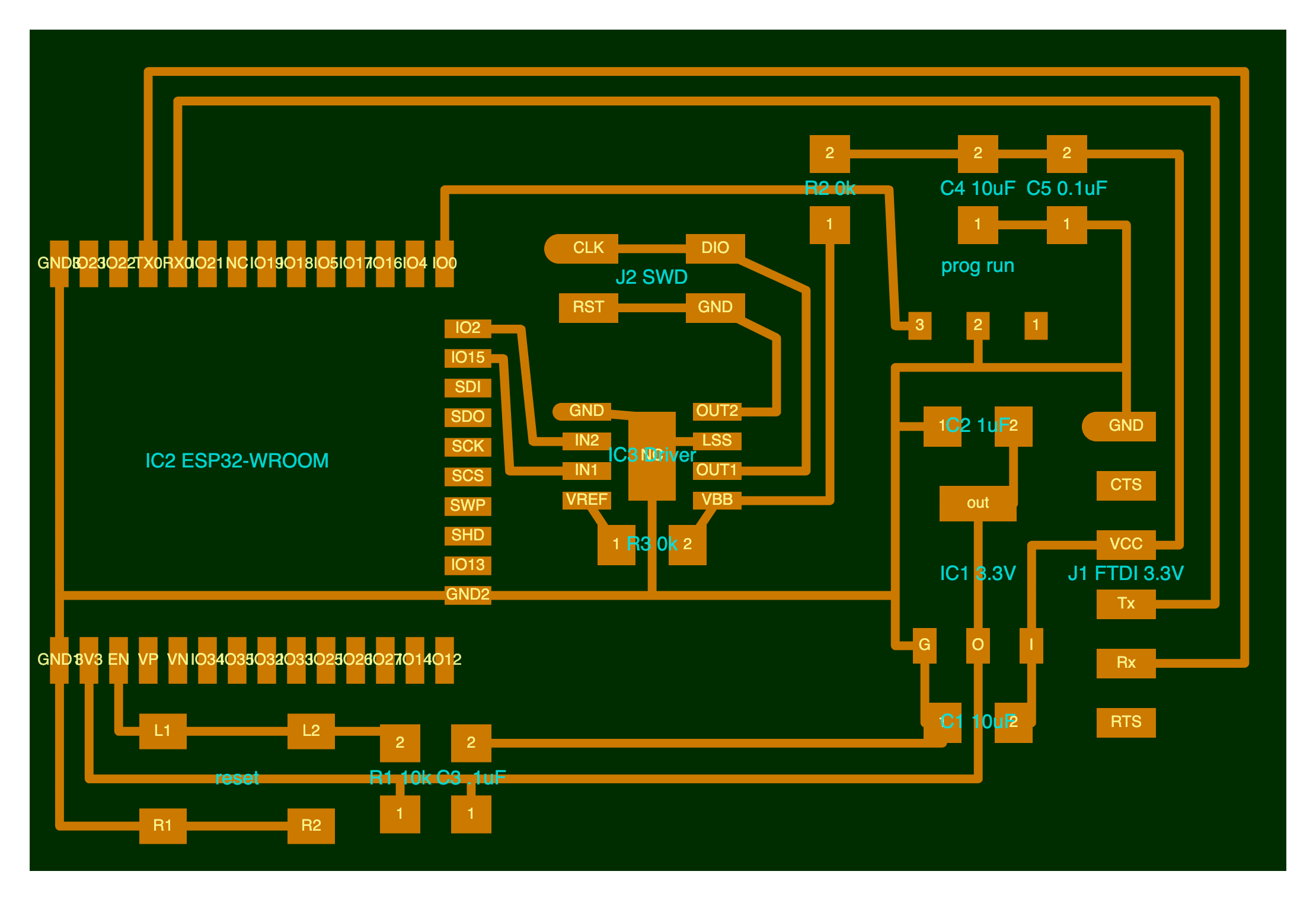
The schematics of the board with ESP32 and motor driver.
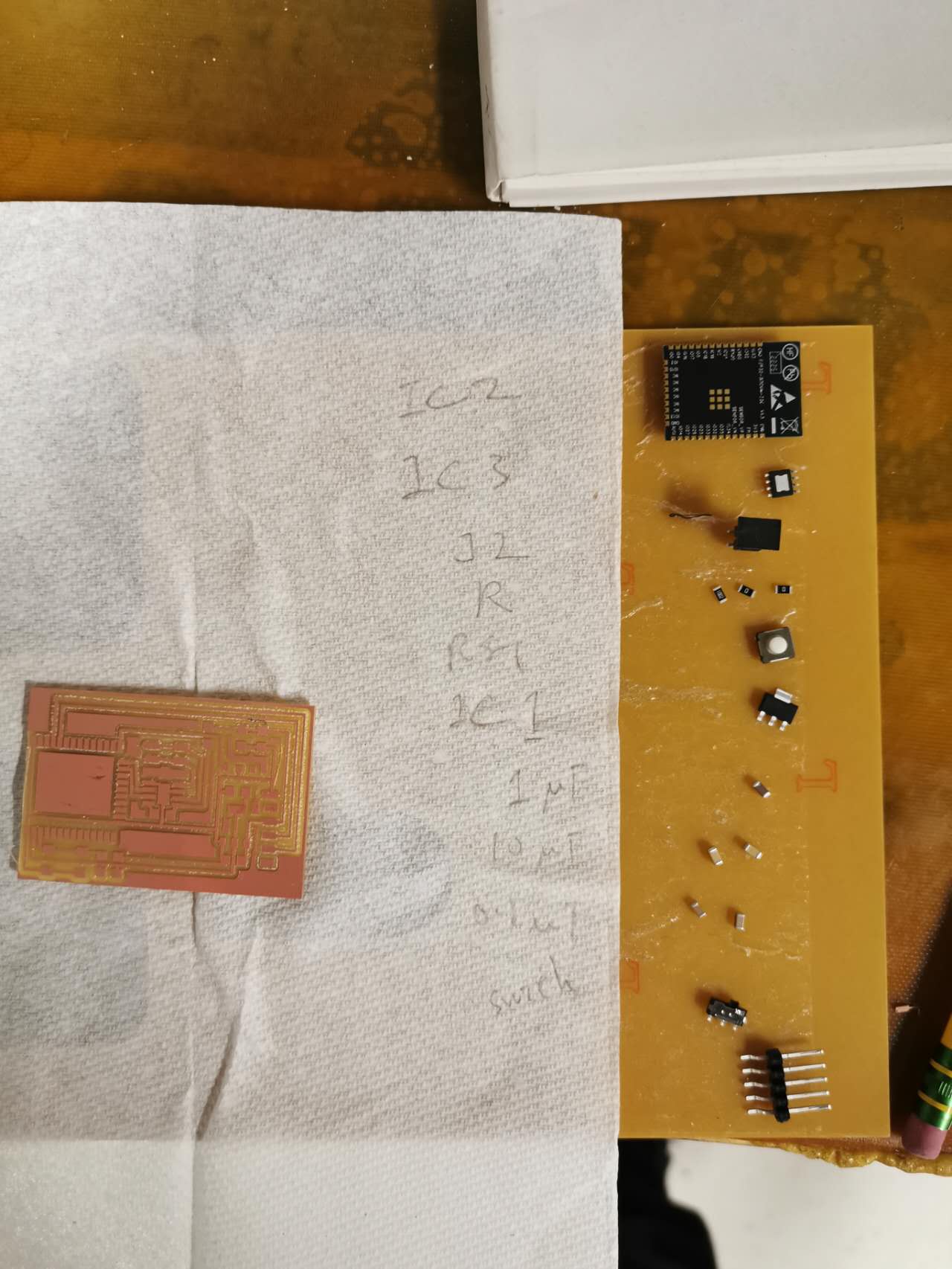
The board milled and parts.
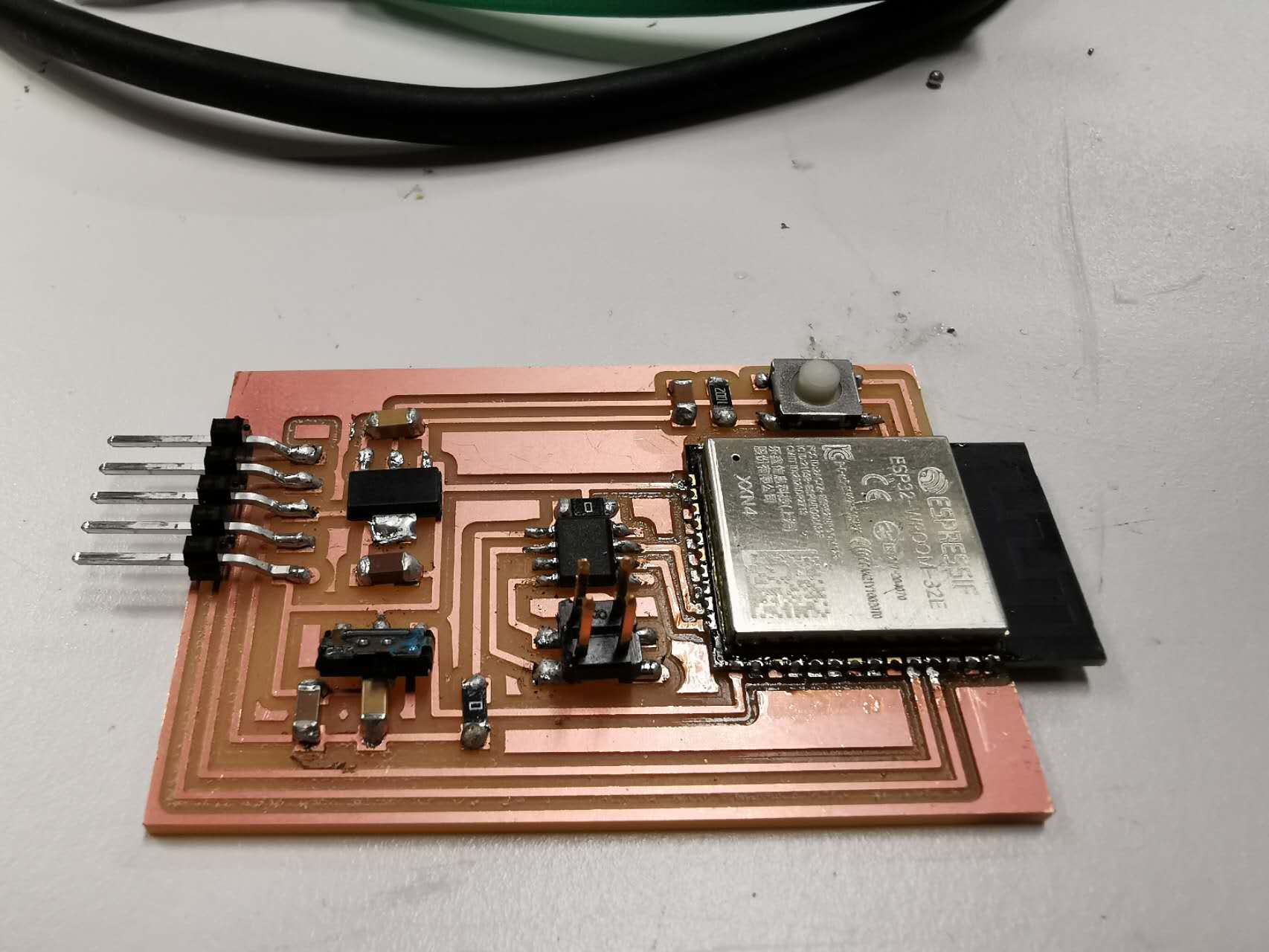
The board ensembled.
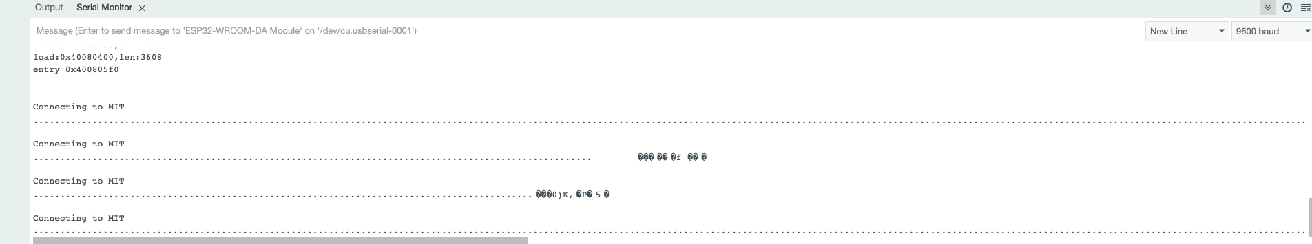
It hardly connects.