04

ELECTRONICS DESIGN

This week, I learned how to use Eagle in Fusion 360 to design a PCB board.

I started from learning a board Neil provided and tried to redraw the schematic of it. During this process, I checked the datasheet of D11C MCU to figure out the meaning of the pins. After that, I added an LED and a switch to digital pins respectively. During the design of PDB board, I added 4 o ohm resistances to corss the lines, which is not elegent. I need to learn how to design a 2-layer board next time.

As for manufacuring, the shop is crowded this week, and when I got a chance to mill, I found out the setting from week-02 doesn't work. The mill cannot penetrate the copper layer. I spent some time adjusting the cyt depth and found out 0.01 inch works now instead of 0.004 inch two weeks ago. However, when I am going to mill the outline, I found that as my boundaries are too close to the images' boundaries, the mods cannot recognize the lines. I plan to tilt the board and output images with larger area of dark. I will try again during the next week.

Tools: Eagle, anothers are same as week-02.
Date: 10.05.2022 - 10.11.2022


PROCESS

THIS IS HOW I GOT THERE


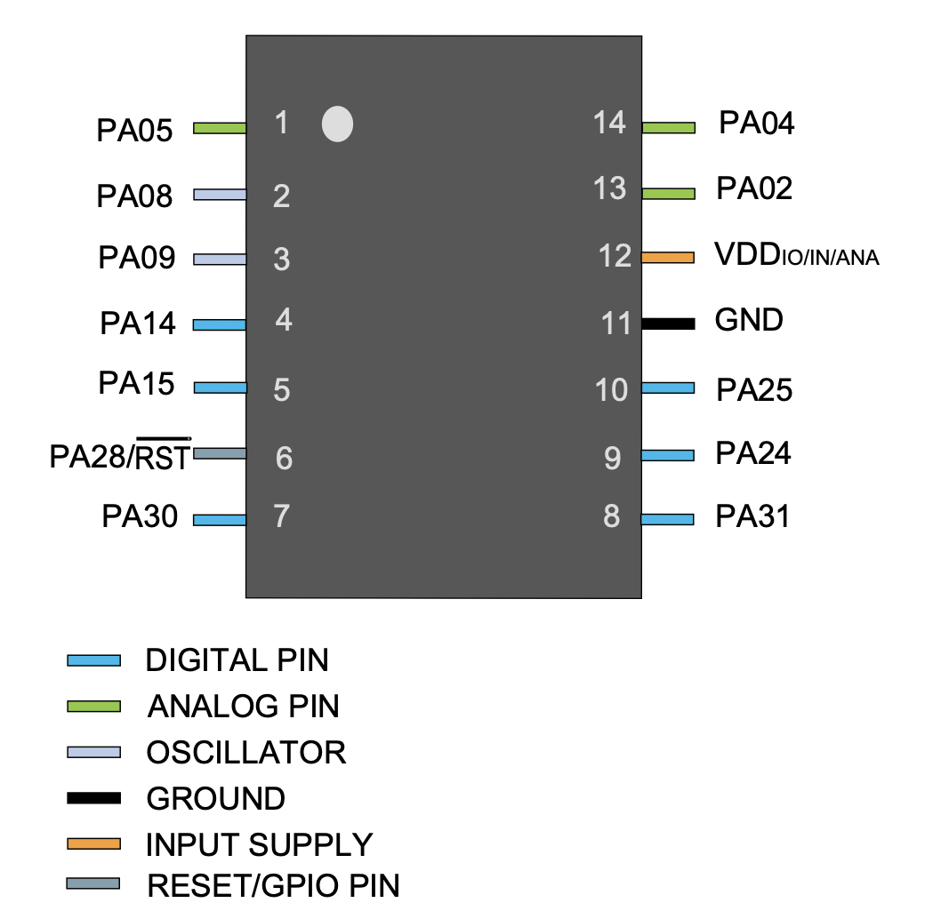
The datasheet of D11c..


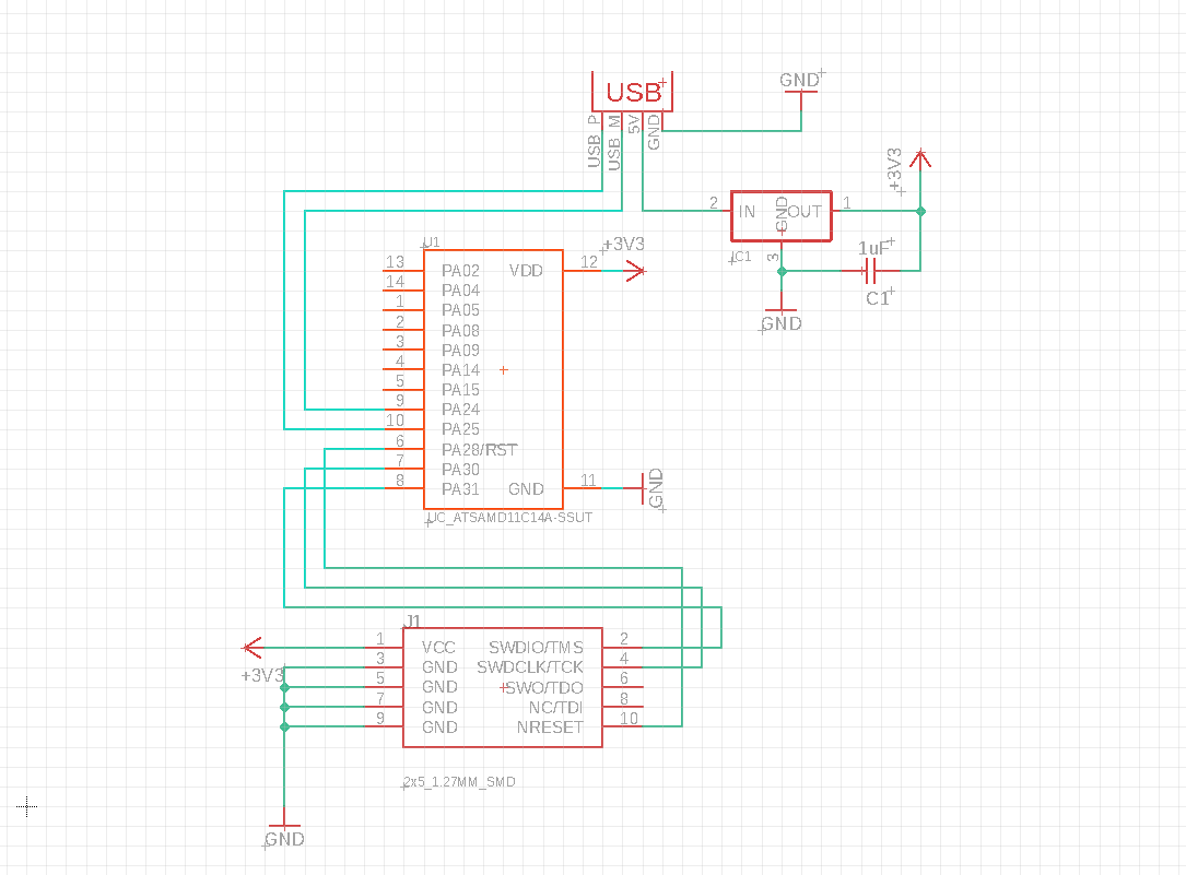
Adding the LED and switch to the circuit.


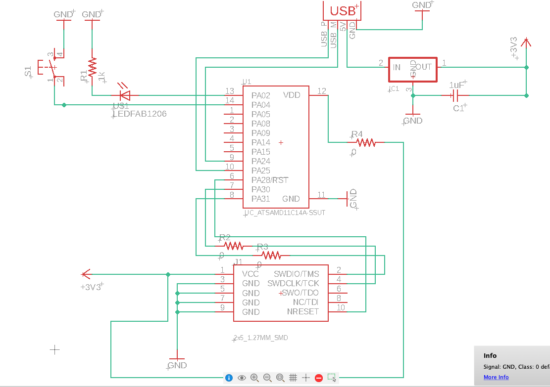
The final schematic after adding resistances.


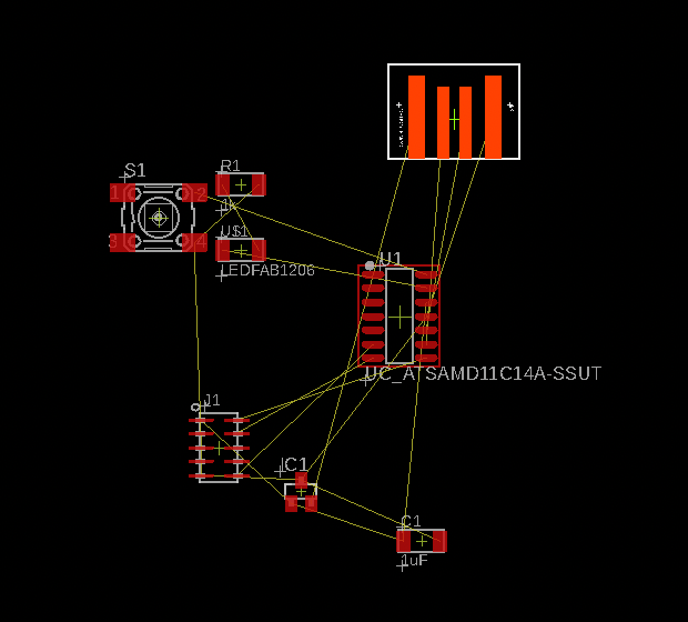
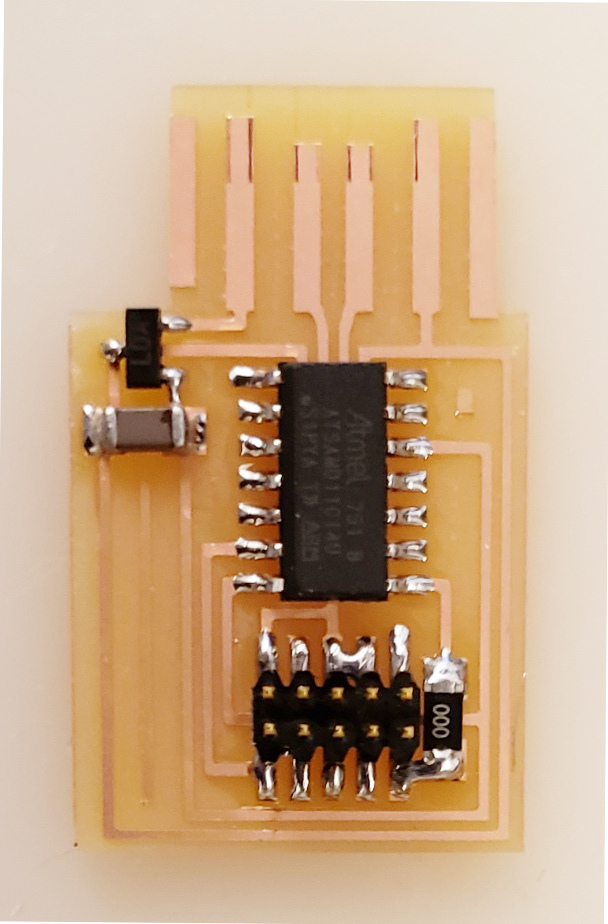
The initial state of pcb.


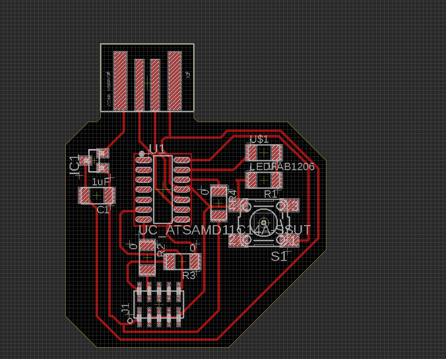
The final state of pcb.
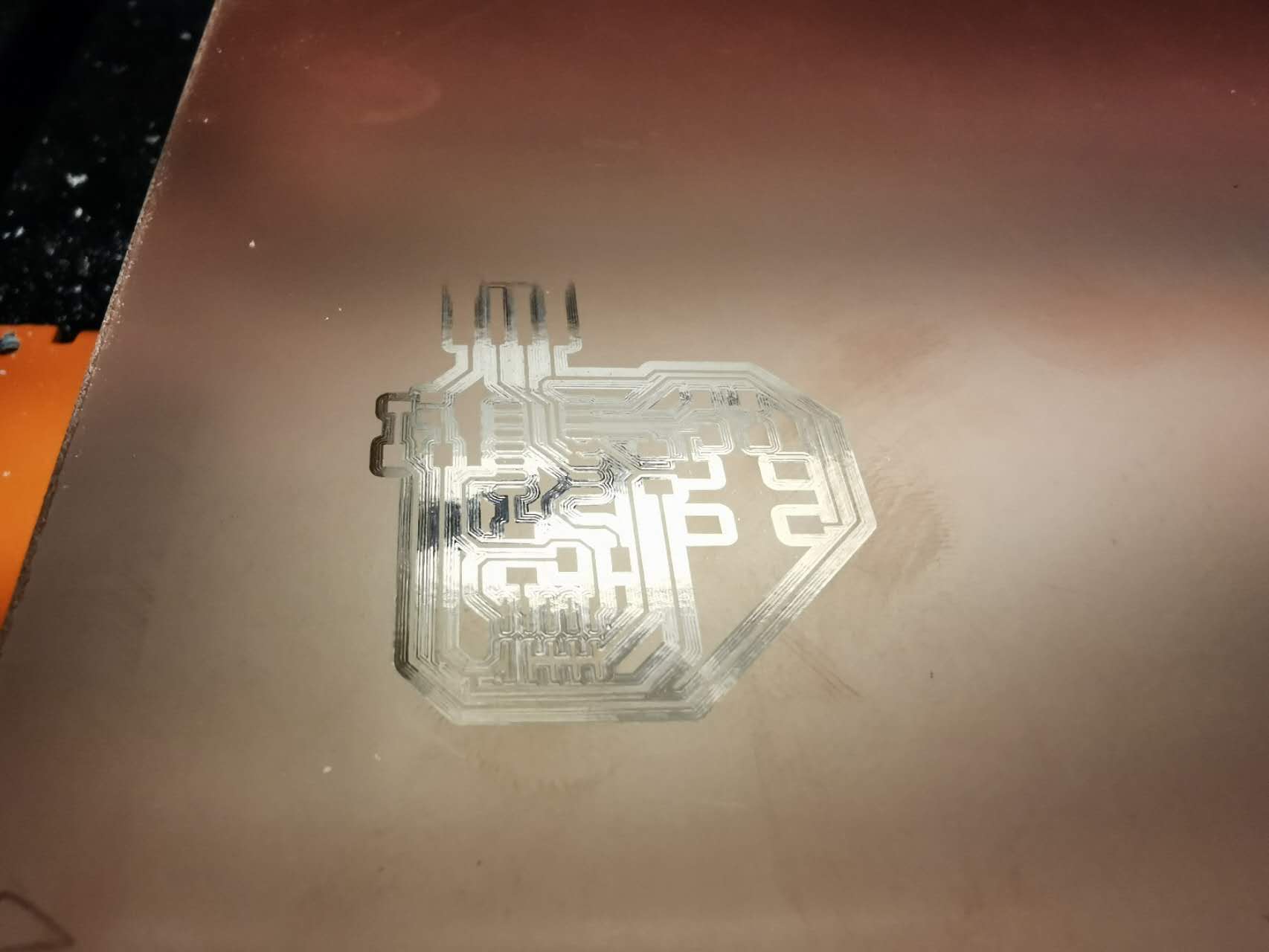
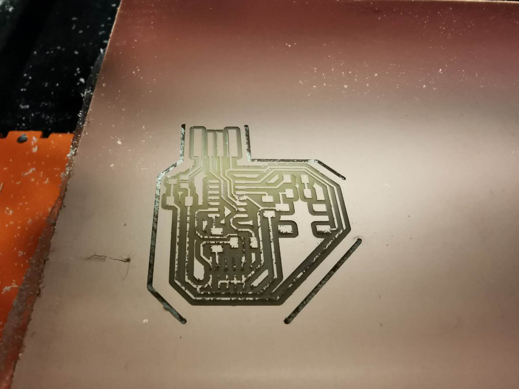


The failed milling.


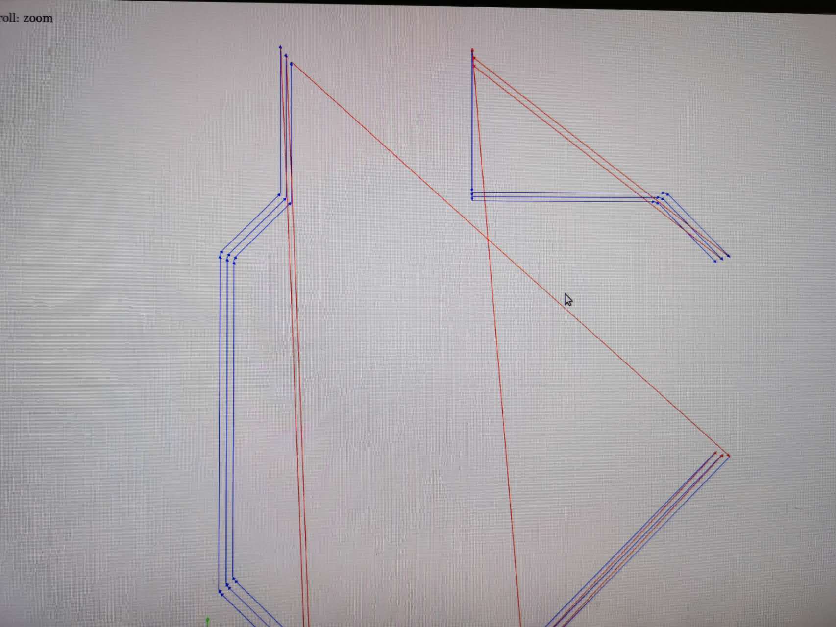
The mods fail to recognize the boudaries.


What I had.