Week 1: 3D Design
- Date: September 7th 2022 - September 13th 2022
Week 1: Designing my Final Project
For my Final Project I have decided to make a new dashboard for my Car.
Motivation
When I'm driving my car, its really annoying to change music. My car is old so it uses an Aux. I have to put my password in and basically distract myself to play music.
Design Requirements:
1. I would like it to fit other future vehicles that I make/buy
2. Should be resistant to noise and reliable
3. Should be easy to interact with
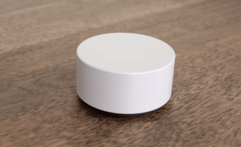
4. I want to have a joystick/mouse that looks like it came from a microsoft product
The Process So far
Dashboard Case/Cover
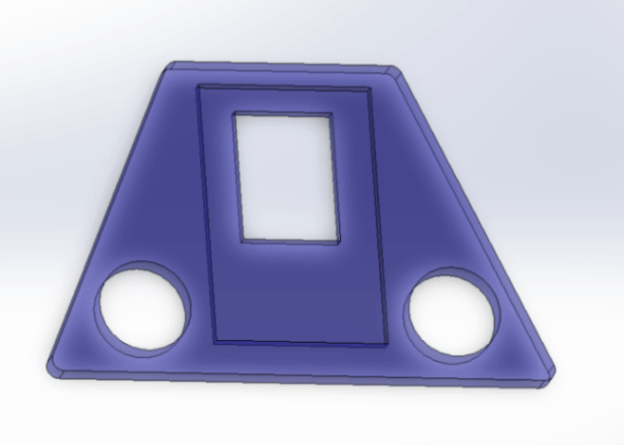
The Main Body
This part will define how my dashboard looks, which in turn will determine how I interact with it.
To Design it I first start with a crude sketch:
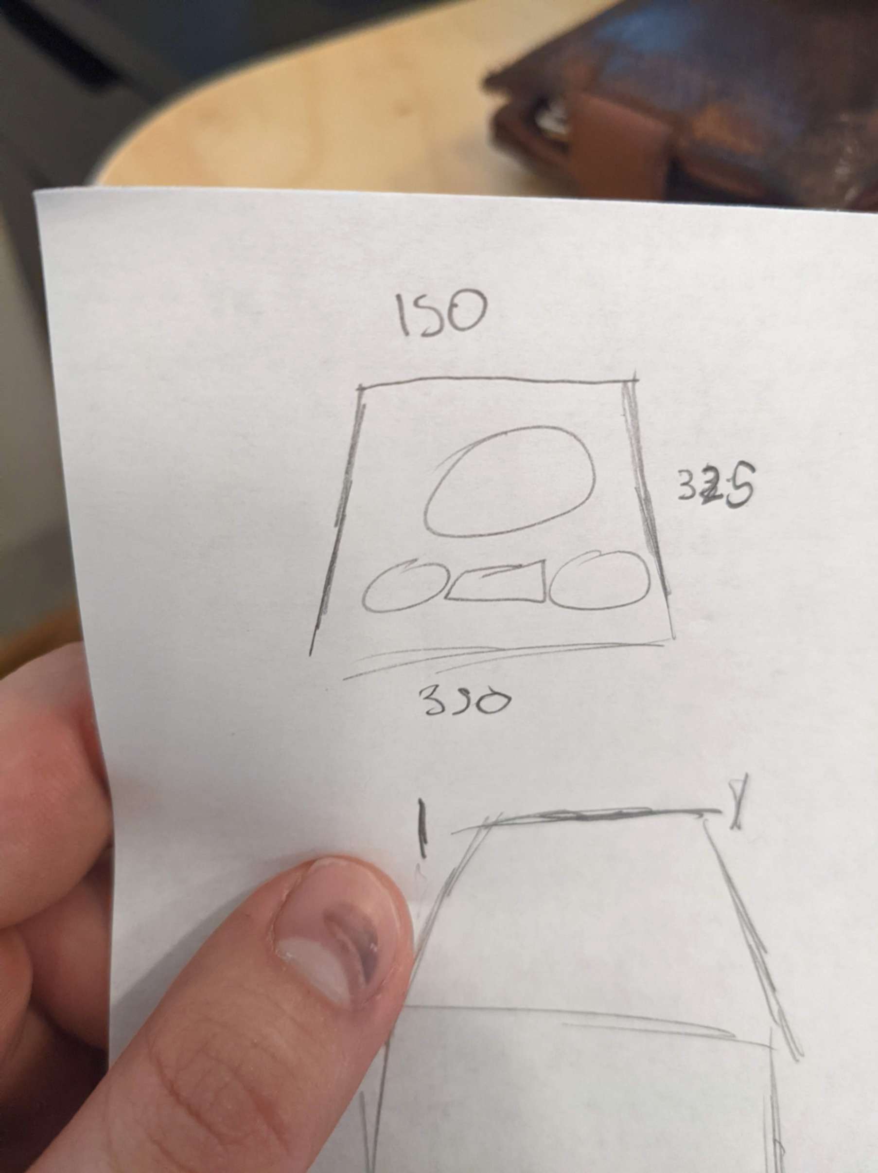
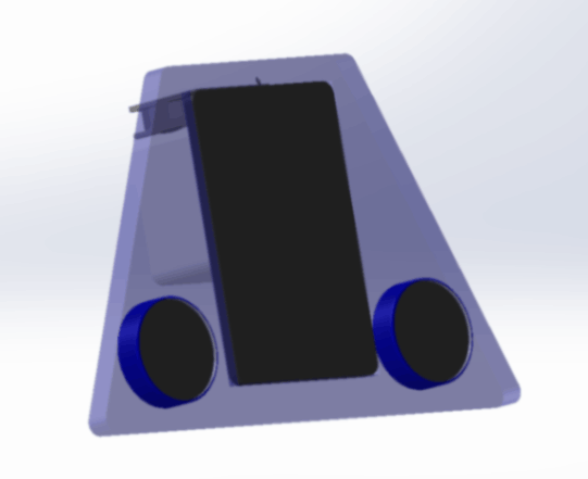
After such a great drawing, I decided to start CADing immediately
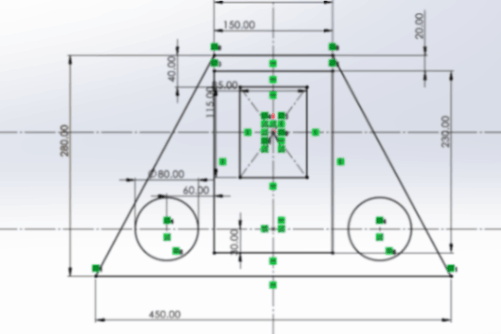
I then extruded the sketch to make the full part
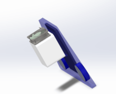
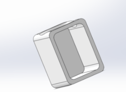
On-board Computer Case
CADing the On-board computer
My goal with having the on-board computer is to be able to interface it with smaller analog/ digital devices that I create. Such as a proximity sensor for when I want to make clean cuts.
Since this will most likely change in the future I designed the main case with as little of the functionality as possible
The Main two things I wanted was a duct for a fan to cool the onboard computer down and also to hold it in place
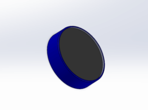
The Screen and Speedometer
the Screen
After CADing all the other stuff this was pretty straight forward. Make a square and fillet and chamfer until it looks like a screen

Speedometer
Putting it Together
the Assembly
This was the annoying part, I wanted to make the assembly in a way, such that when I edited a component sketch it will auto update to the assembly
However whenever I updated a part I would get an error in the assembly mates
After a short learning curve I learned not to reference faces or features when mating. The proper way is to reference sketches