Week 5: Electronic Design
- Date: October 6th 2022 - October 12th 2022
Making a PCB with a OLED Display
Task: Design a version of the Echo Hello World Board with at least a button and LED
For this weeks assignment I decided I wanted to design a PCB for my final project. This PCB will act as the audio display for music and will sit on the dashboard of the ATV.
The Base Design
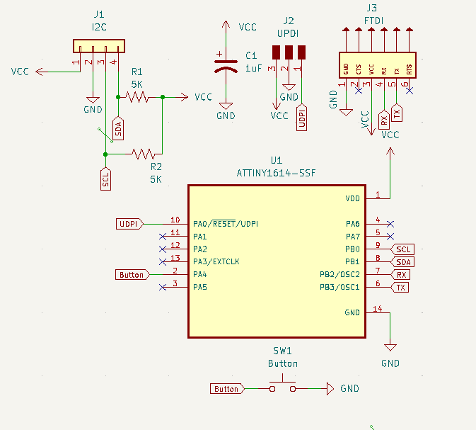
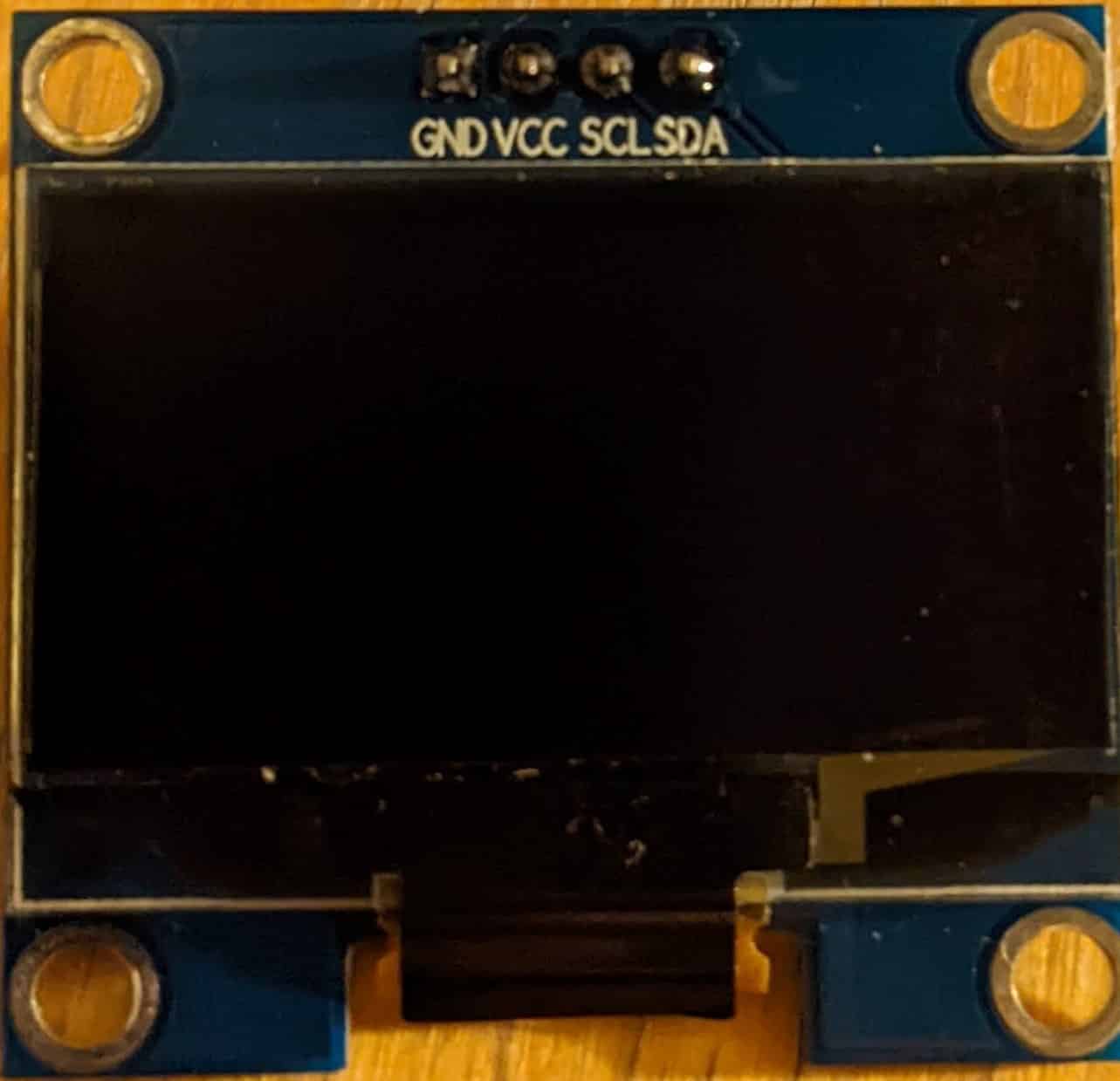
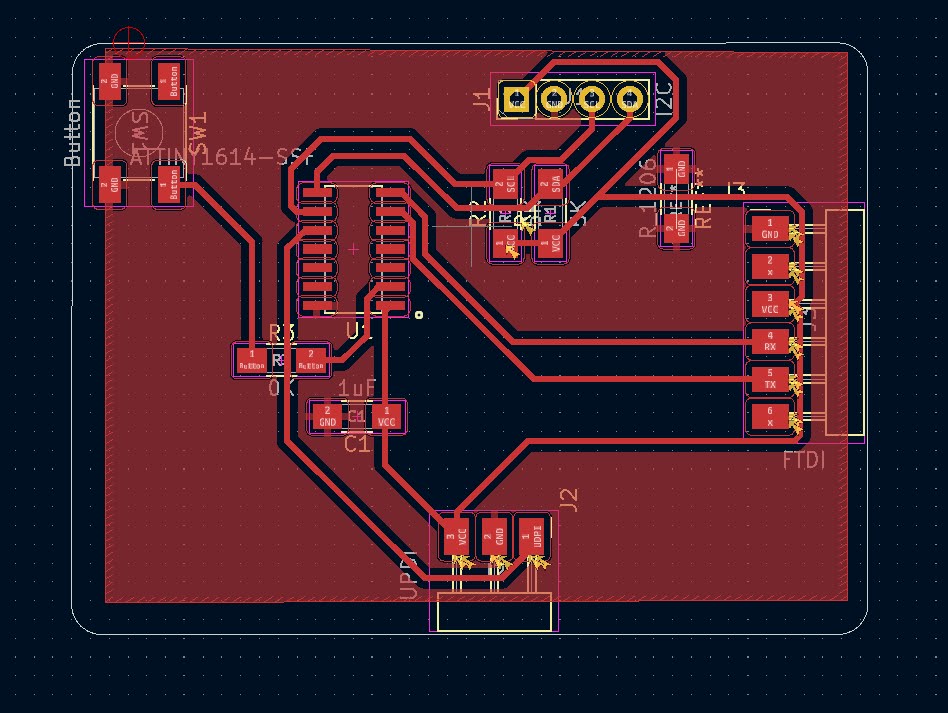
Before I started I had to figure out what components I want to use. I first started with the MCU (MicroController); I picked the ATiny1614 this MCU has 20hz clock and can be powered with either 3.3V or 5V supply. Next I chose the OLED screen, I found a standard 0.96inch SSD1306 OLED in the lab which Anthony was kind enough to give me. Next I needed to configure a Serial Output port and a Programming port. Reading the datasheet for the ATtiny1614 I found that I can program the board through UPDI and read Serial via a standard serial port. Since UPDI is just serial with RX and TX tied together to program all I need is a USB to serial programmer which we have at the EDS lab. Utilizing this information I was able to design a schematic. I added a small button which can be configured to do something later.
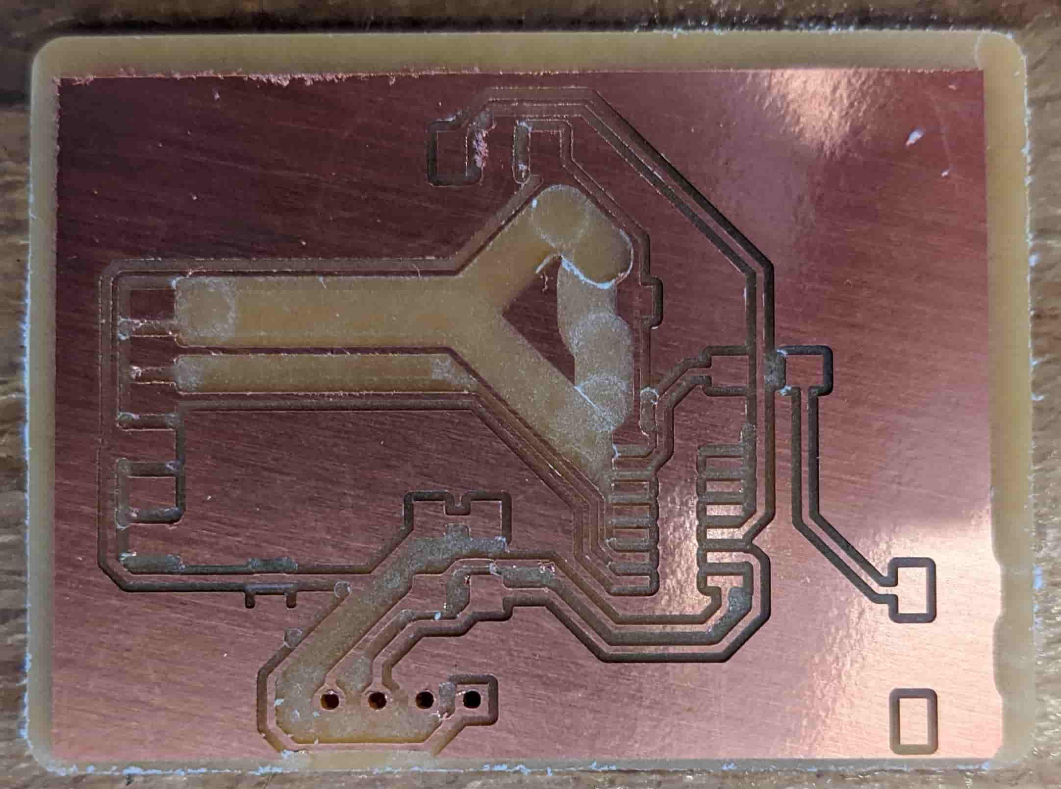
Routing the Traces and Milling the Board
After laying out the schematic and checking all the pins I began routing the traces. Before I started I set the constraints of our machine into my design, from a couple of weeks ago this was found to be 16 mil trace clearance and width. Once the design rules were set I was able to start routing traces. This was fairly annoying, at first I tried to do it with as little 0 Ohm jumpers as possible. However, I soon realized how futile this is and embraced the jumpers. I ended up with only 2 jumpers. I added a ground pour which is nice cause all the grounds would be connected and I end up with less to mill out.
Once I routed all the traces I ran it through the DRC (Design Rules Checker ) to check everything was within the constraints. The results came back with no significant errors (had 3 for the jumpers). Then I generated the gerber files and sent it to the mill to be milled out. The results were great I didn't even need to sand the board like last time. I used 1/64" PCB conservative, 1/32" flat end mill, and 1/8" flat end mill to mill out the board.
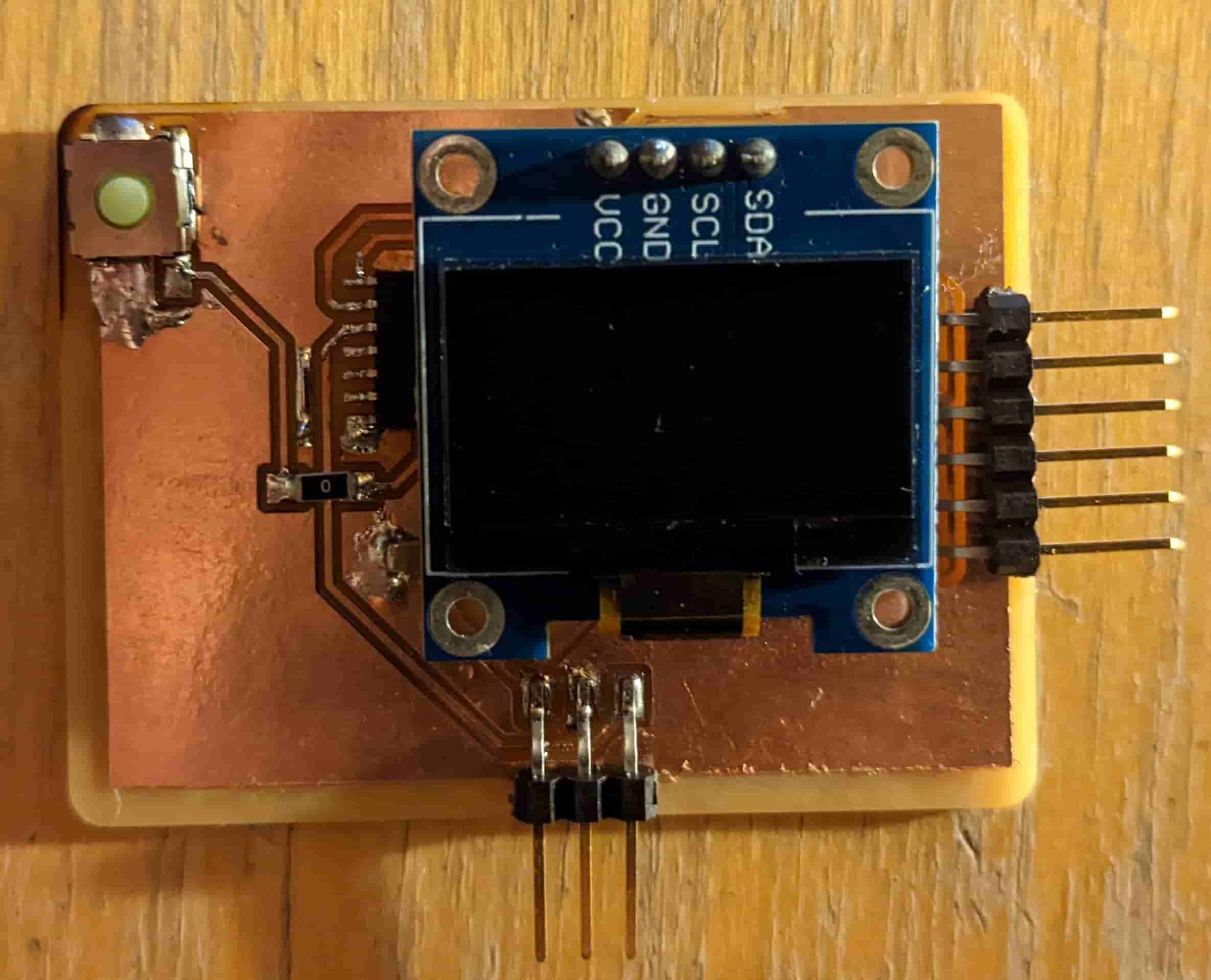
Soldering and Placing the Components
I'm glad to say that I really learned my lesson from last time. I was patient and waited for a proper station to open up and used flux with only a tiny amount of solder. This time around my soldering came out quite well. However, my nice soldering job was soon overshadowed by a few shorts on my board. I removed the components from my board only to realize it actually wasn't my soldering it was just a tiny piece of copper left over from the mill. Something that I would have caught if I sanded the board. Lesson learned again.
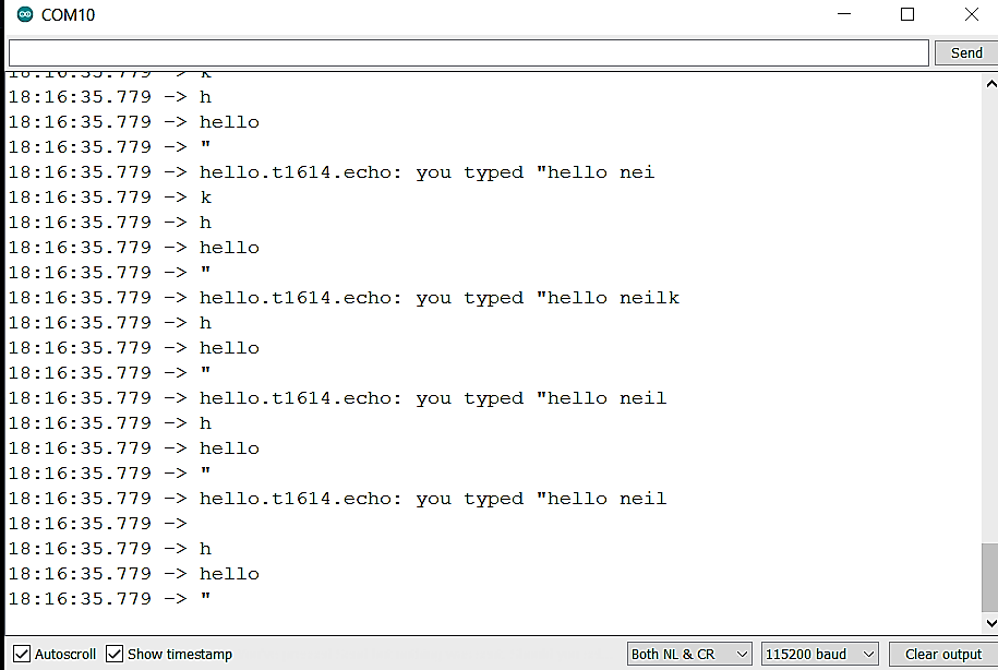
Programming the Board with Echo Hello World
Now for the real test. To prove that my design met the bare minimum of success. I needed to program it with the Echo Hello World ino file. To this I first configured my Arduino IDE to be able program the ATtiny MCUs. I followed the instructions laid out by our well versed TA Anthony. First I opened up my Arduino IDE and went to File > Preferences > Additional Board Managers and added this link http://drazzy.com/package_drazzy.com_index.json . Then I went to Tools > Board > Boards Manager and Typed ATtinyCore and downloaded the manager by SpenceKonde. Then I reloaded my IDE and went to Tools and selected my board and chip which is the ATTiny1614. I also selected the Programmer to be "Serial UPDI - SLOW". After configuring the IDE and connecting my board though the UPDI port. I compiled and uploaded the echo sketch successfully. Then I plugged the programmer into the FTDI port on my board and was able to send and receive responses. Finally, my board works.
Programming the Board with my Custom Display Firmware
After having a successful initial test I was feeling confident enough to push my board to the limit and see if everything is working. So I wrote my custom firmware to change the OLED screen to black when the button is pressed and white otherwise. Small disclaimer I downloaded the Adafruit GFX and SSD1306 Arduino Libraries (Tools > Manage Libraries). And Since the pins I used for I2C were hardware I2C I just needed to compile the code and upload.