Week 7,
Execution Phase : Unfortunately, my CAD-ing endeavors were farrrrr from over. After showing my design to Anthony, he told me it was nigh not possible, even
with the Othermill. The smallest tool bit size was 1/32" so none of my features could be engraved which meant I needed to change my design to have only raised features that were at least 1/32" apart. Furthermore, the curved band was resulting
in trailing cuts as the mill is better suited for horizontal surfaces. Anthony suggested rolling my ring mold to be flat which meant I could mill all around the band. Unfortunately, I really wanted to cast with metal this week and that strategy
would have resulted in a (pretty cool) silicon / flexible ring. So instead, I did a pretty large overhaul of my initial design, resulting in two horizontal bands on either side of the ring, where I added design features. My quote was way
too long to reasonably fit while also being big enough to mill so I instead decided to do a minimalist representation of the quote (you'll see what I mean). Once I'd designed a ring that I felt could be reasonably machined, I had to make it
into a mold. To do so, I split the ring in half and put it in a square mold with walls a quarter inch thick and space for ~1/2" of Oomoo surrounding each side of the ring. To make sure the molds would line up when joined, I added three pegs
to one mold and holes in the other so I'd know which piece was the top and by fitting the pieces together, I could ensure my ring was aligned.
After doing so, I could then start deciding on the CAM for my parts. To take out most of the solid from my mold, I used an Adaptive Clearing operation, with speed settings of 15000 rpm and 50 in/min. This helped take out most of our unwanted
material. Following that, I did an initial Parallel operation which smoothed over the band of the ring and flattened the sides of the mold. For my part with text and a flat band, I included an initial Flat operation which basically clears
all the areas that should be flat in the design. So far, my toolpaths used the 1/8" flat-end mill. I then switched to the 1/32" flat-end mill so I could begin getting detail and starting the finishing process. I did another round of the Parallel
toolpath, this time with perpendicular passes as well. I constrained this operation to only work on the ring itself, as I didn't see the need of using machine time to clean up the mold. I then did a Pencil operation which only worked on the
horizontal part of the rings to clear up some detail. To finish up, I did a Contour operation to make my layers more distinct and finally, on the text ring half, I did one last Flat operation to finish up the text. One good way to see
if your CAM is over is to keep simulating your toolpaths and taking note of your final result. It's not guaranteed that your mold will look like your CAD so I kept going back and forth between seeing what operations
sounded like they'd be useful and then testing to see what their expected result was. The expected final result of the sum of my operations are shown below
(ignore the red around one of my models as that's a result of Fusion simulating a shorter 1/8" tool than the one I'll actually be using)!
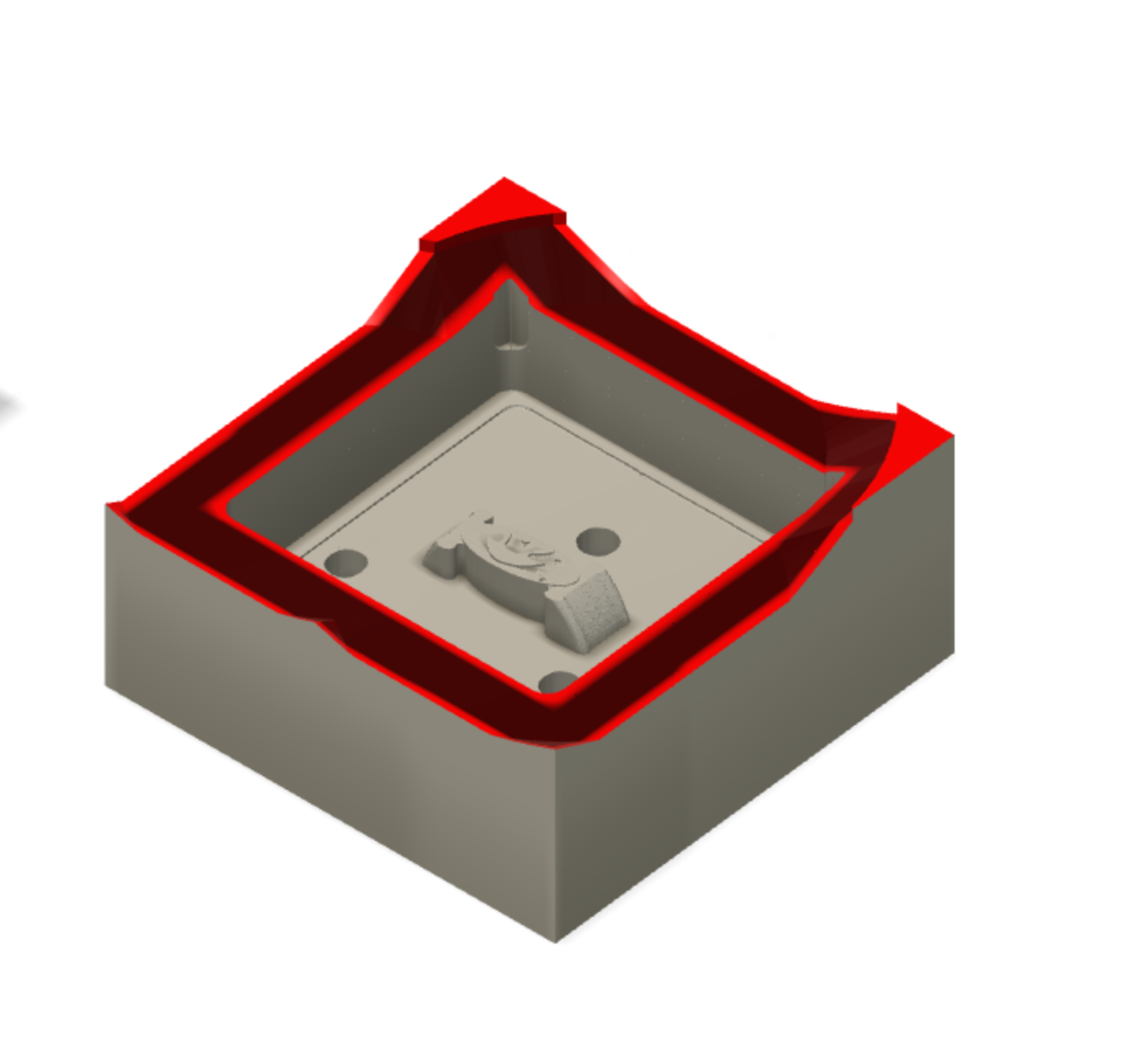
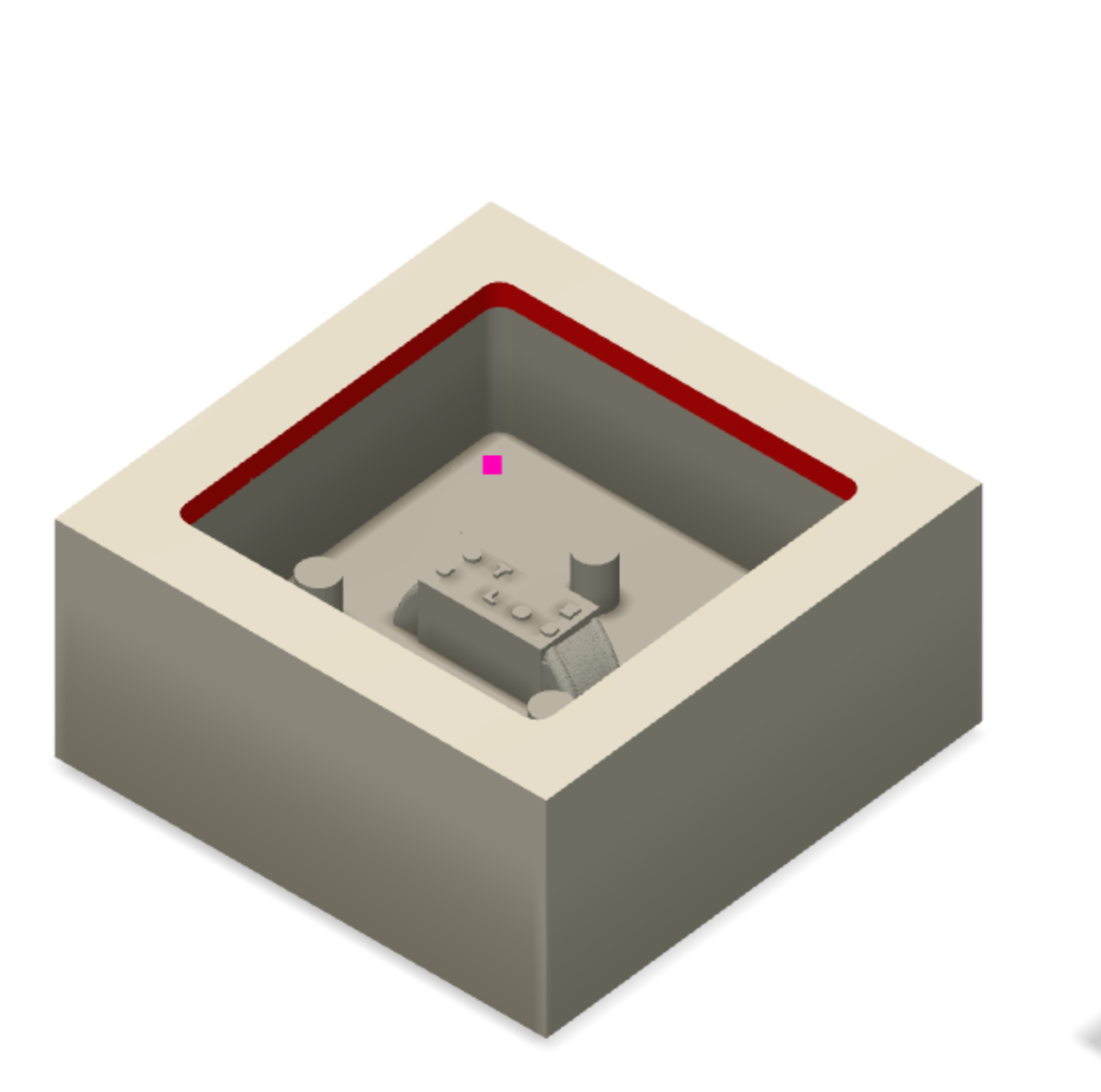
After deciding I liked my CAM
toolpaths, I reduced my total machining time by restricting the bounds of some operations (like I did earlier with the Parallel toolpath) and making retraction rate the minimum possible. This resulted in an estimated maching time of ~18 minutes
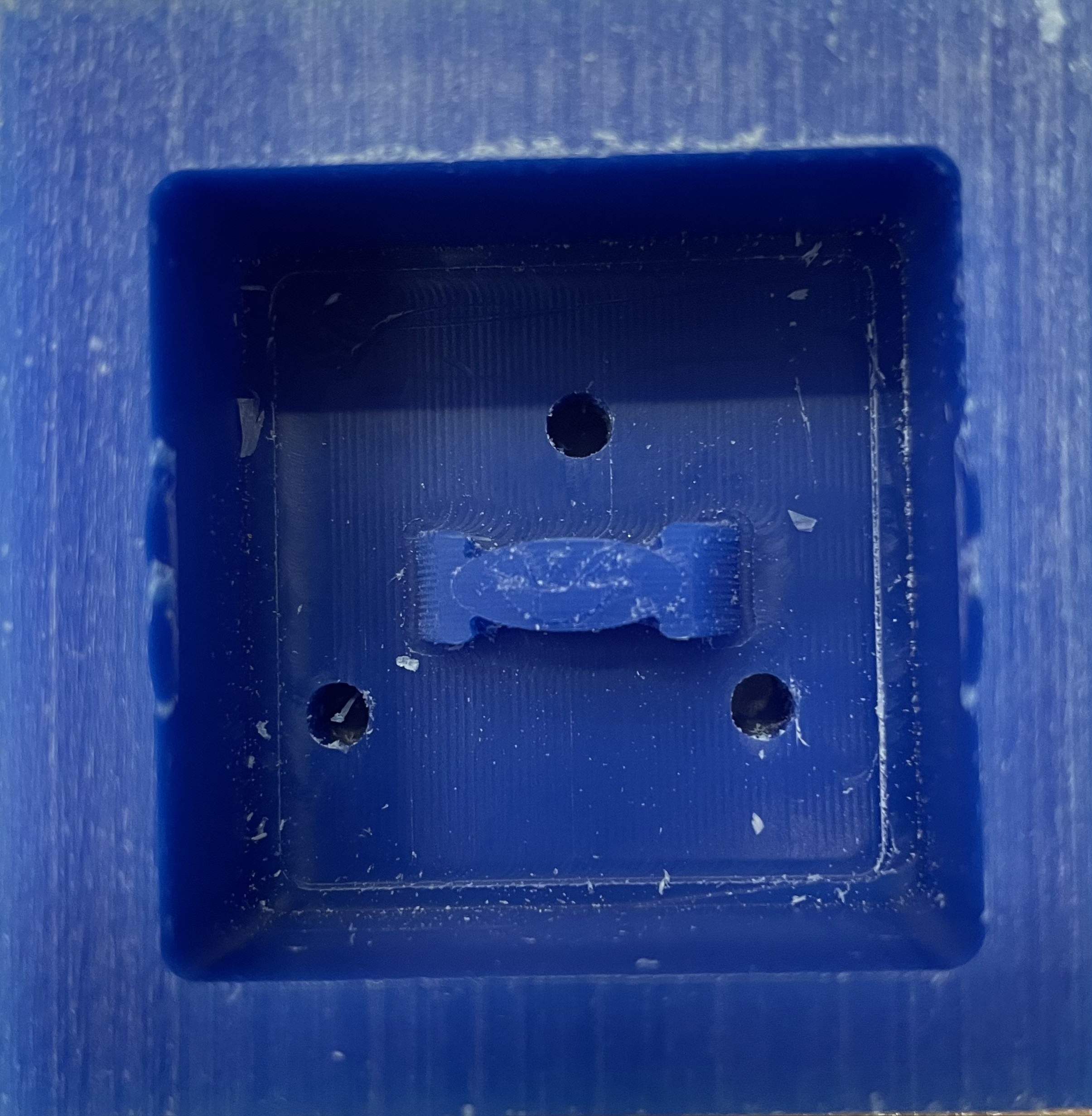
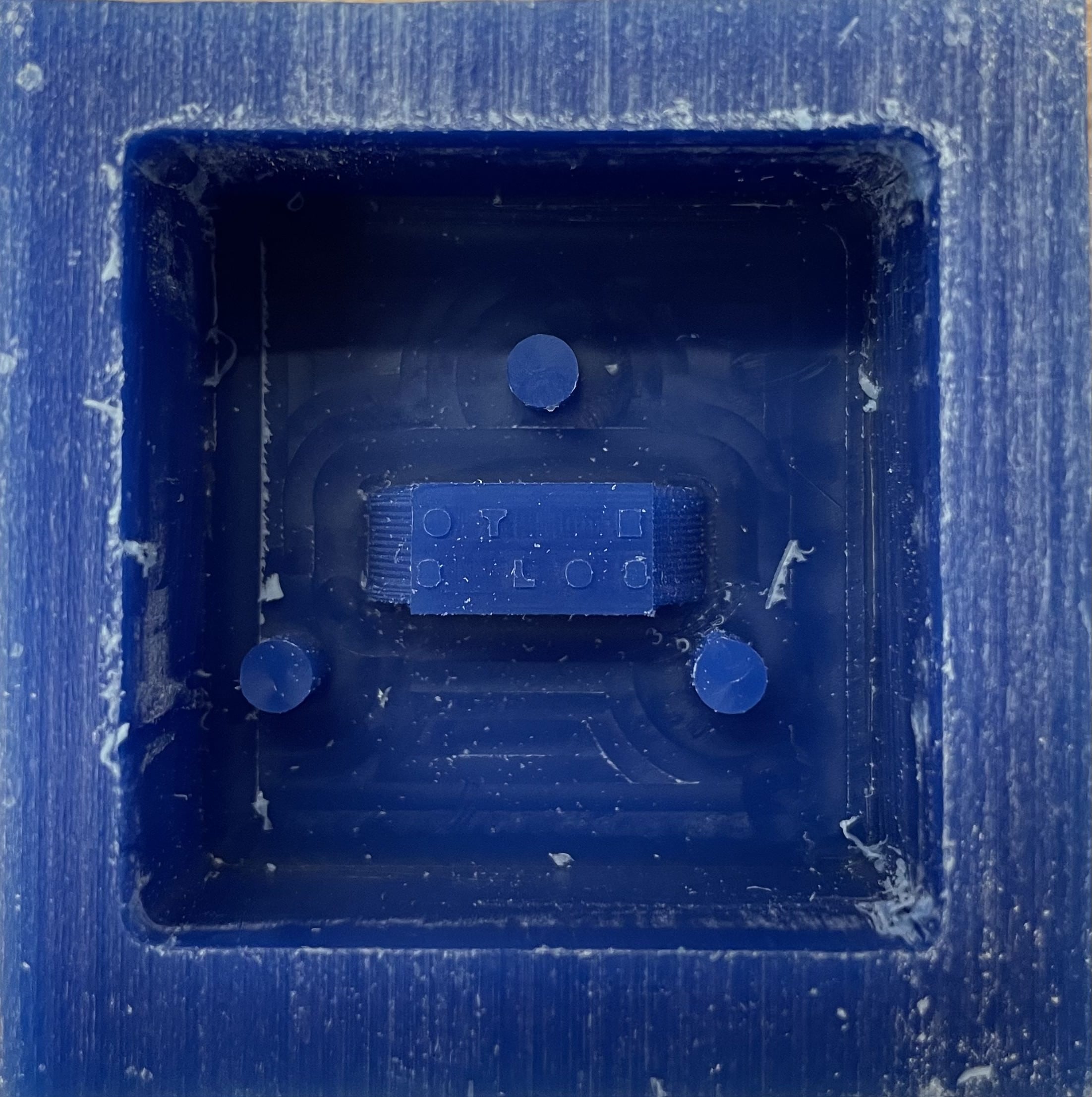
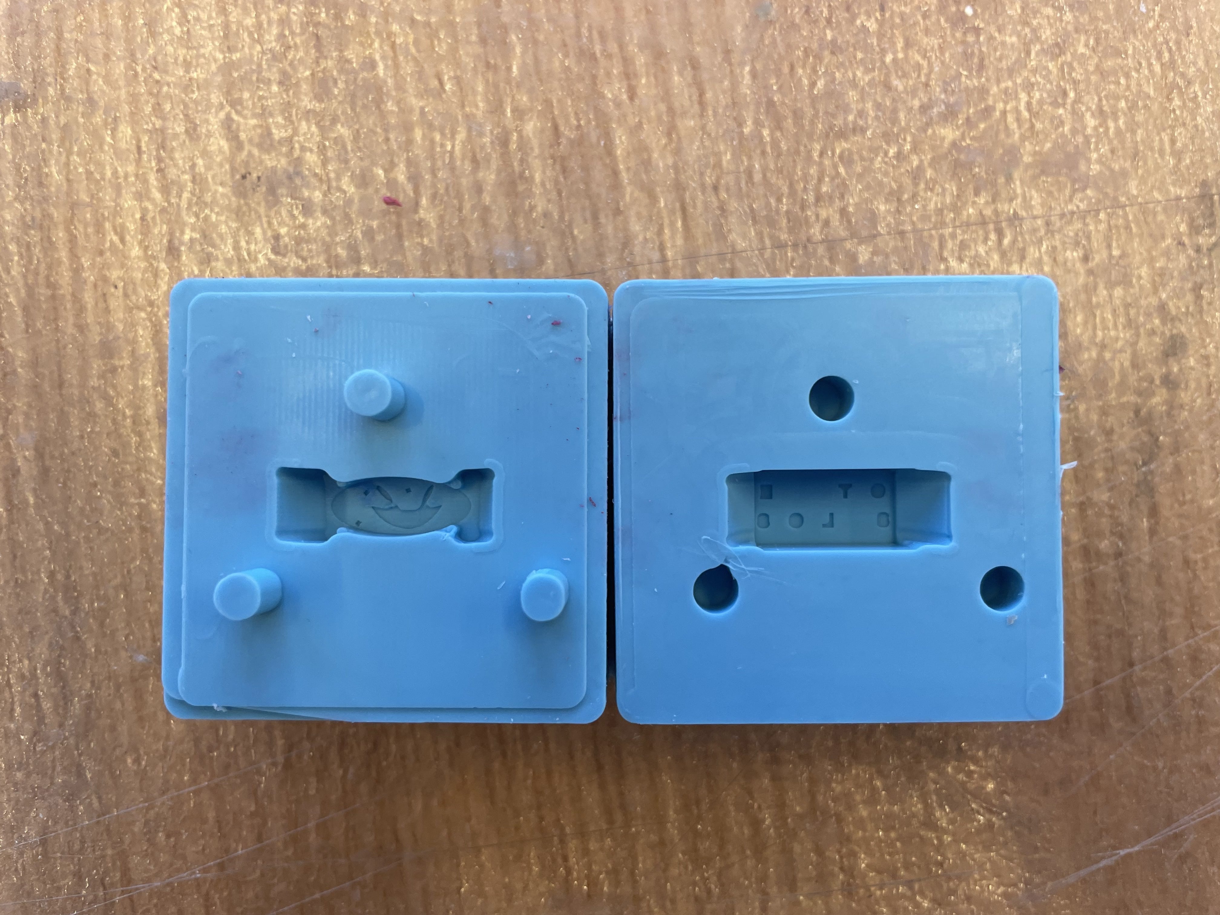
per part which translated into an actual machining time of about half an hour for each part. Since I've worked with the Othermill for PCB development, milling was not much of a hassle. I will say, I forgot how small 1/32" is. Looking at in CAD
makes it seem much bigger than it really is but look how teeny these features are:
With that done, I worked on my Oomoo negative molds. Oomoo is a 1:1 ratio mixture of two parts, two parts that I didn't realize I should measure for accuracy so rather I guesstimated that they were 1:1 much due to Anthony's shock.
Regardless, I poured my not-so-accurate blend of Oomoo into my molds, left them in lab to set overnight, and hoped for the best :)
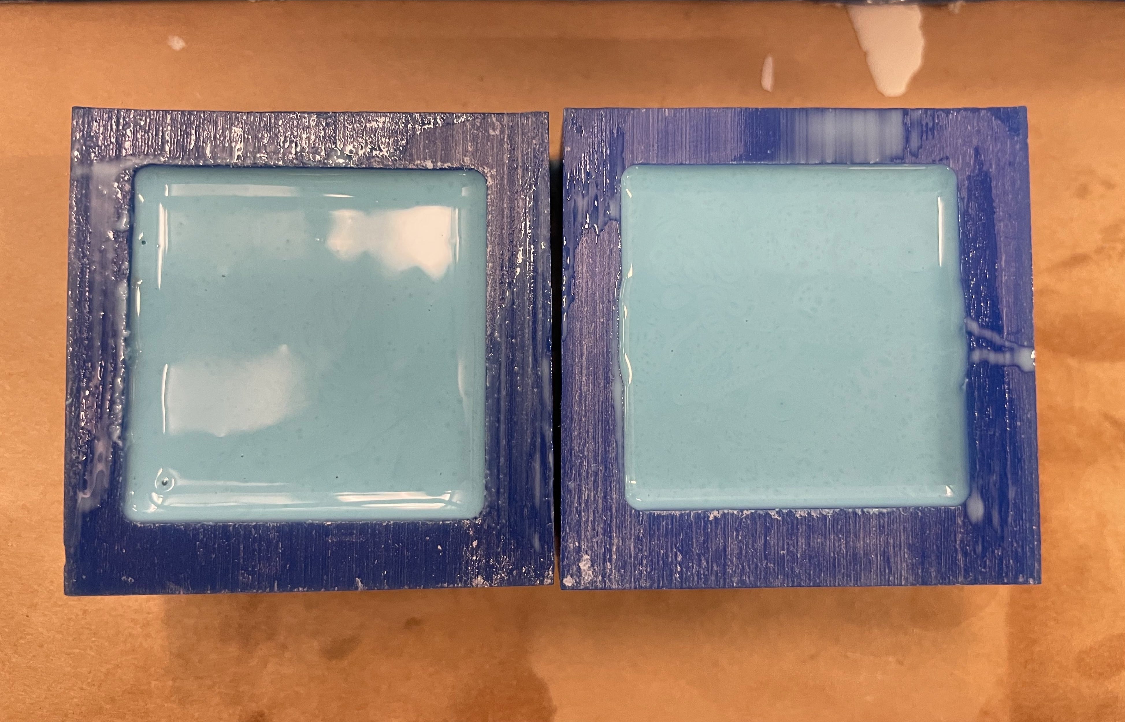
And against all odds, it worked!
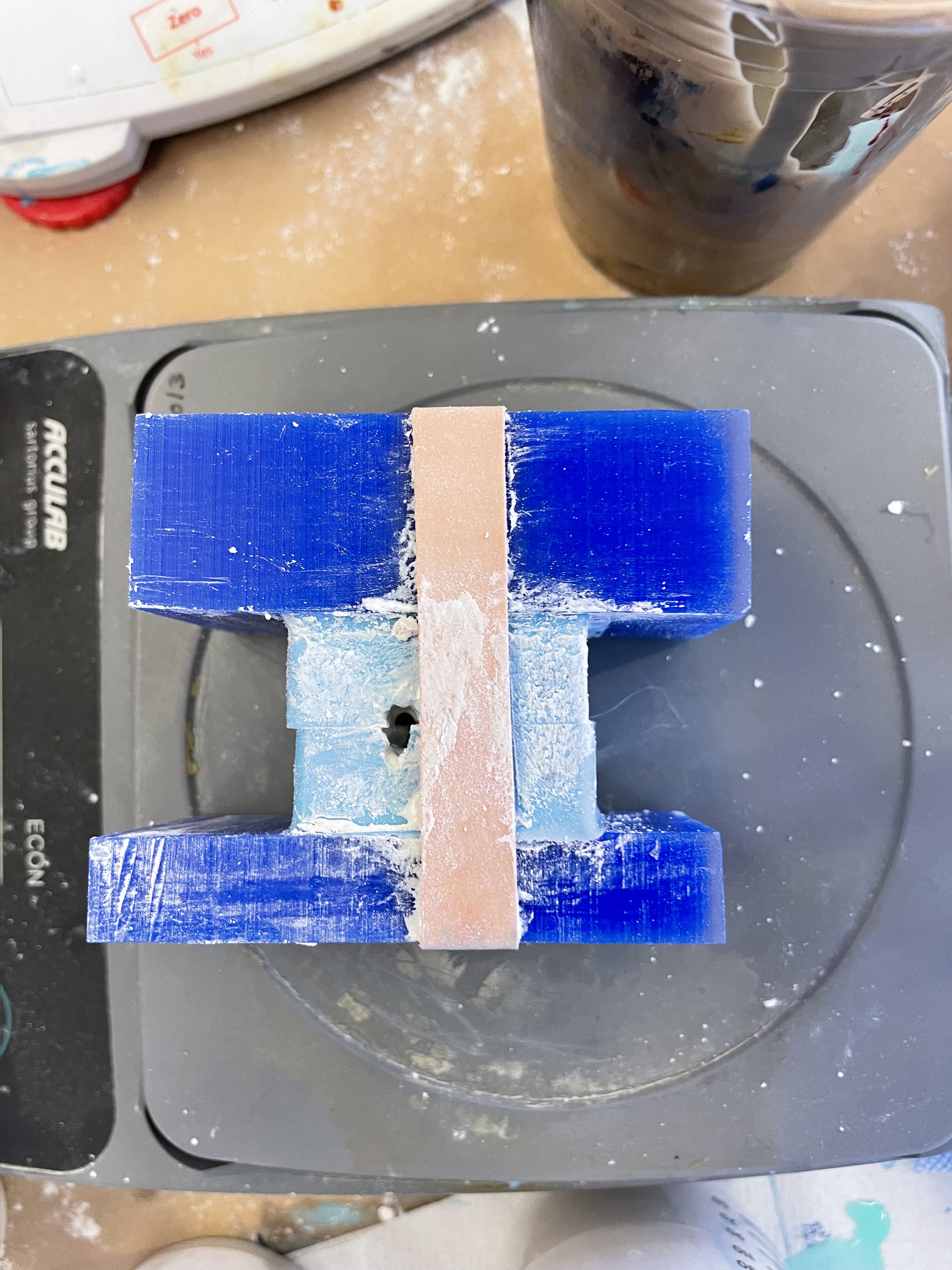
Since metal casting is happening in bulk later this week, I decided to see how the ring looked with a drystone cast. Perhaps my previous success with guessing about the Oomoo had gone to my head because I didn't measure the drystone and I
was very unconfident about the results. Even the way I was pouring it into my mold didn't seem the smartest. So with low hopes and a makeshift jig, I waited for the drystone to..dry.
Those low hopes turned out to be somewhat true. While my drystone eventually dried to the right consistency, it seems that my mold doesn't completely line up (either that or I'd distorted it when making my pour spout. I tried again but this
time I casted the two halves separately and connected them with a thin drystone layer. It still came out oblong which means there's probably something wrong with the shape of my CAD itself. Luckily I have some time to fix that and re-mill
before metal casting happens so I'm glad I prototyped.
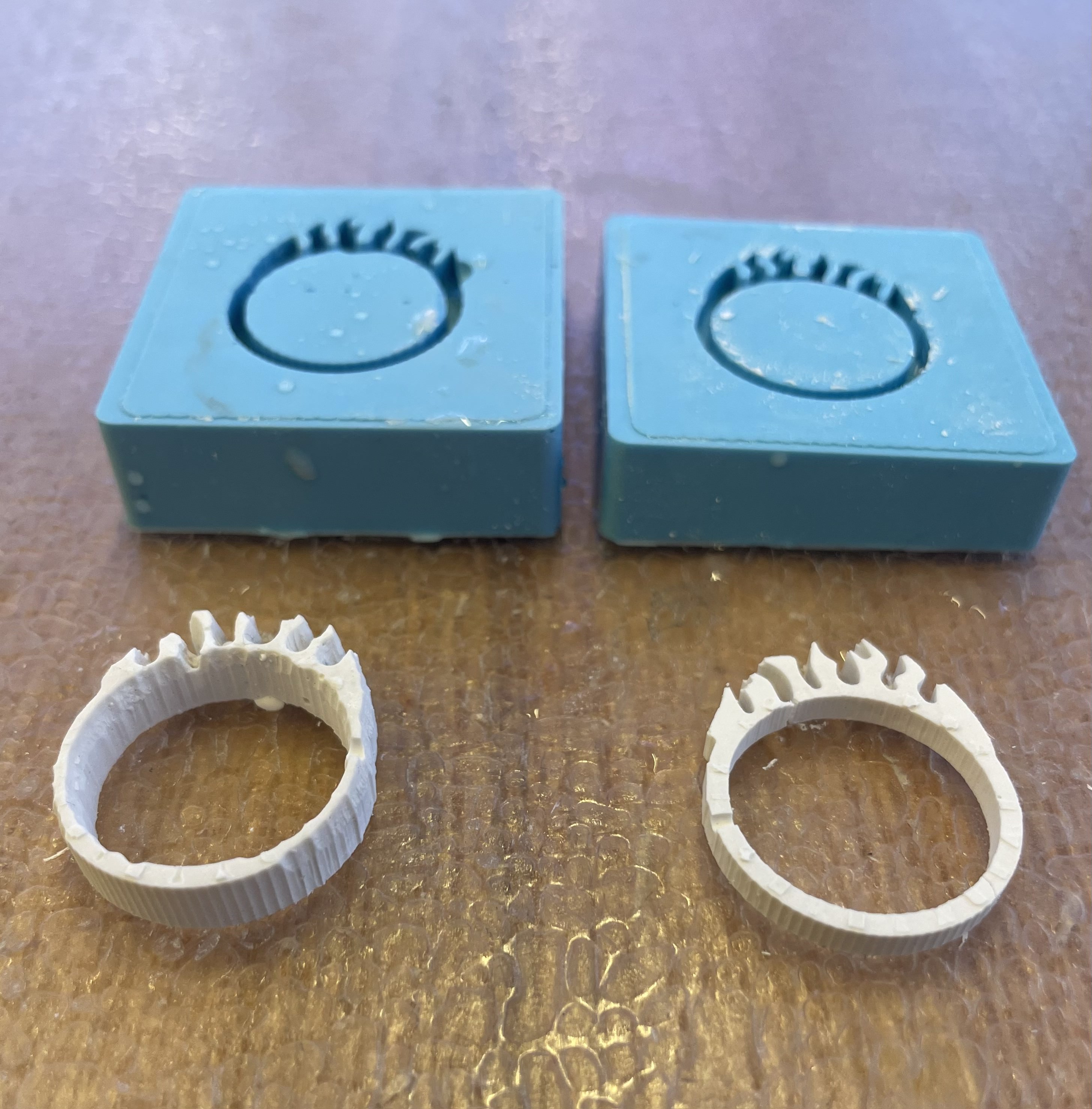
Final Product: In an unexpected turn of events, I decided to re-design my ring altogether and came up with a new CAD design which did not need to be
a two-part mold, to fix my alignment issue. The CAD, oomoo negative, and drystone product are shown below -- I did two different attempts, the first being a taller ring which lost a lot of detail because the ring's height
was taller than the 1/32" mill's length of cut. I didn't realize how important that is because when something's height exceeds the tool's LOC, it starts to crash into your part and ruin detail.
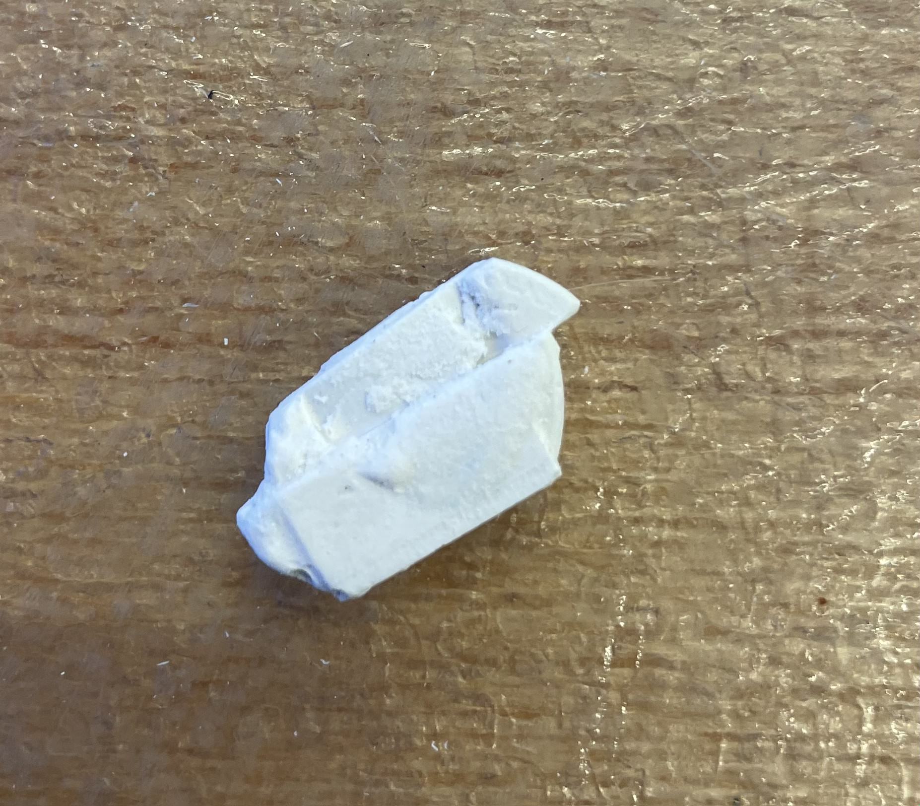
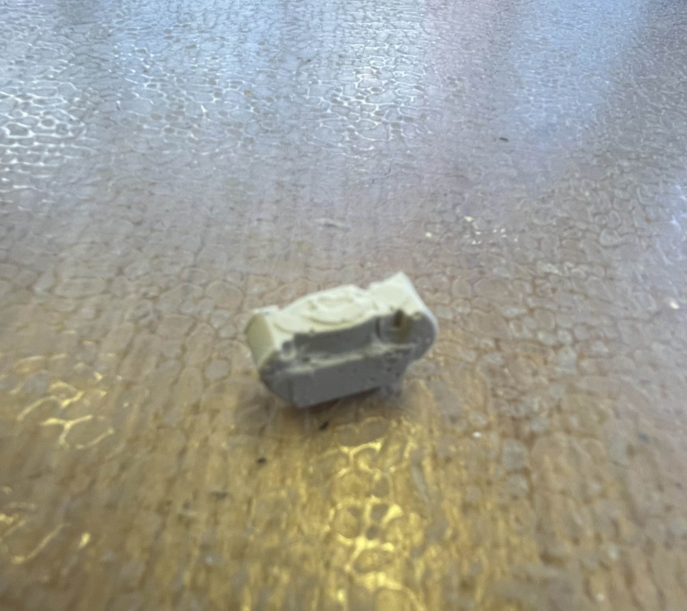
Despite the shorter ring being more successful in terms of milling and detail, it unfortunately snapped when taking it out of the mold, despite the fact that I'd let it set for two days. Metal casting hasn't occurred yet but I have hope that
the metal version of the shorter ring will be more structurally sound :)
- Alex