week 12: Build a machine!
a drawing machine.
This week, each section built a machine. My team had discussed what we wanted to do in the previous weeks so by the time the week came around, we were already ready with our idea. The plan was to build a drawing machine. The machine would take a png of a drawing, slice it, generate gcode-like code, and then send it to the machine to draw. Our plan was to use the coreXY system offered by the TAs.
We split into hardware, firmware, and software groups. I was in the firmware group; I will detail our findings below:
What we did:
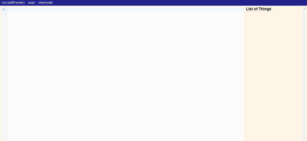
The firmware team's job was to write up the code that would tie software outputs to hardware instructions. In preparation for this week, the TAs compiled a backend structure called "modular-things" (https://github.com/modular-things/modular-things). Their system allowed us to modularize every aspect of the machine-- every spinning component had its own name and variable in the code.Using the modular-things as a starting point, we were presented with a sort of javascript IDE:
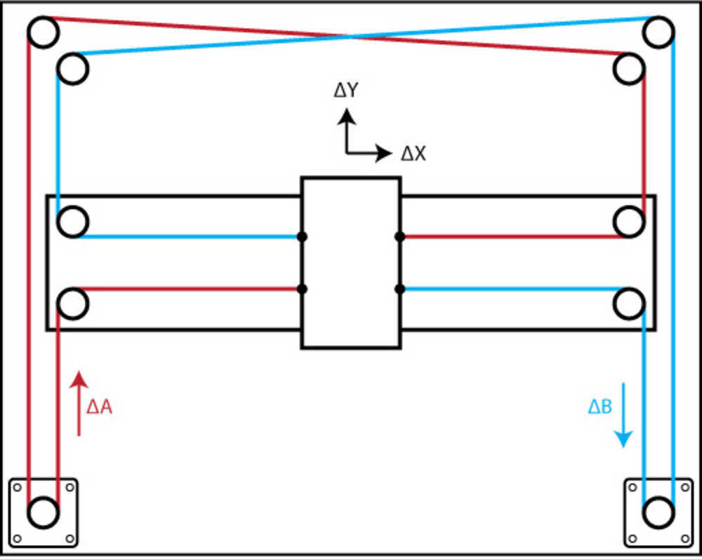
To start, we flashed a bootloader and uploaded arduino code onto the USB/SAMD21 boards we connected to our two motors and servo. The arduino code was pulled from the modular-things github; it allows the motors to be found and translates the higher level javascript commands to a language the SAMD21 can understand. We hooked up both motors and, using the corexy function "createSynchronizer([amotor, bmotor])", we were able to tie the motors together, such that a single location command would cause them both to move. This was necessary because of the structure of the corexy system:
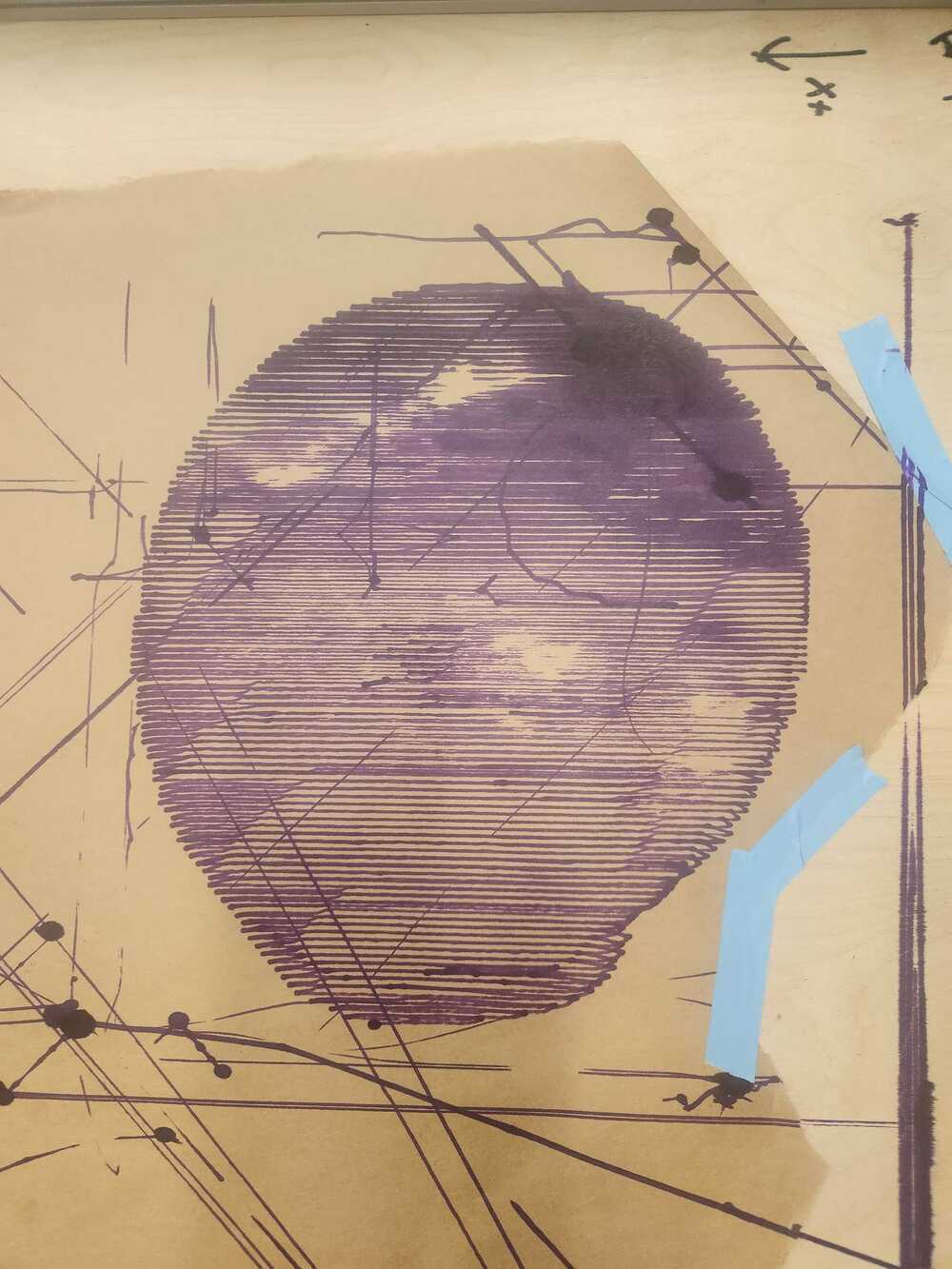
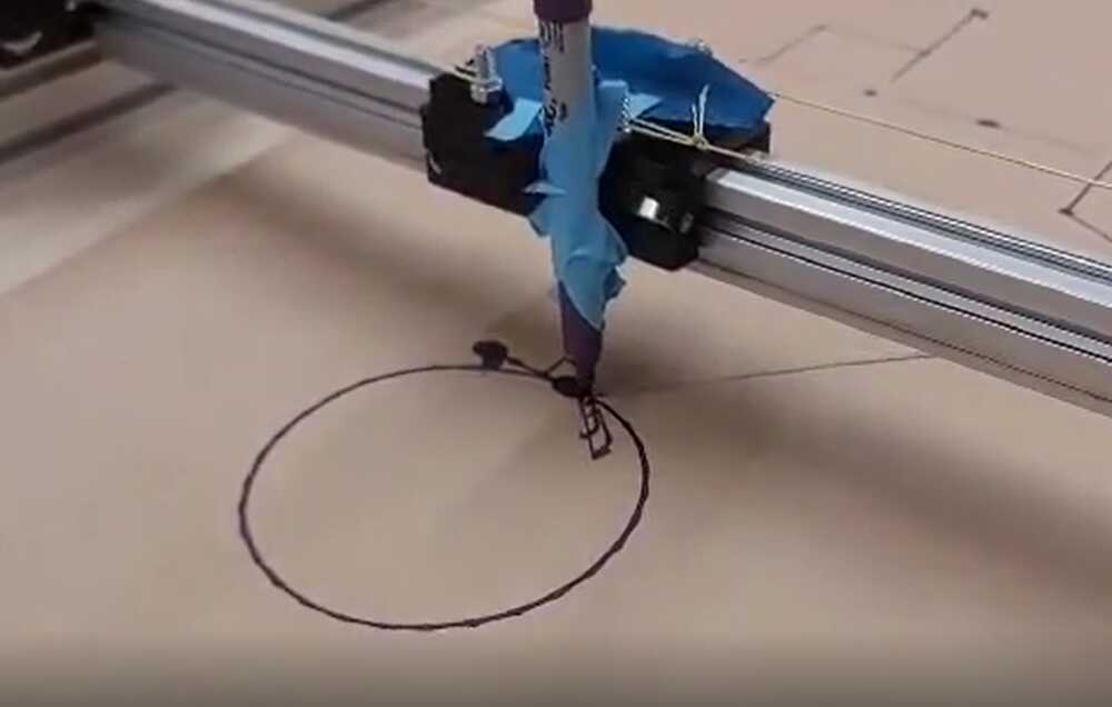
The next step was hook up the motors (now dubbed motors a and b) to the machine and to test some example commands. The motors, in the modular-things environment, came with 2 types of directions: relative movement and absolute movement. Relative movement would take input x, y coordinates and add them to the current absolute coordinates, while absolute movement would go to the absolute x,y location given regardless of starting position. We taped a sharped to the place the end effector would be and ran some absolute coordinates to draw a circle (aka sending cos(x) * radius, sin(x) * radius locations in a for loop). This was the result:
Even though we gave just the locations of the outside of the circle, the machine traveled in and out of the circle, drawing different parts of the outer ring at different times. We concluded at this point that the "createSynchronizer([amotor, bmotor])" function that tied the motors togther did not account for the fact that the motors did not function in x,y -- as mentioned before. Given this distinction, we began to refer to the input coordinates as x,y coordinates and the coordinates necessary load into "createSynchronizer([amotor, bmotor])" as a,b coordinates. Given the setup of the corexy system, we found that the relationship between the x,y and a,b coordinates were as follows:
a = x + y
b = x - y
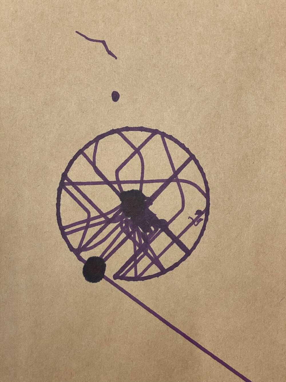
We set up intermediary relative and absolute movement functions that would complete the x,y to a,b transformation for us. Once we did this, the circle was drawn as expected:
Next, we focused on getting the code to read the outputs of the software. The software was written in python and produced commands as a list of tuples. Each tuple contained x, y, and z values. The plan was to read the x,y values and send them to the motors while reading the z value (binary value) into a conditional that would tell the end effector when to pick up and put down the drawing utensil.
We copy and pasted an example list into the code and ran into issues of the pen randomly ramming into the sides of the machine, even though the inputted picture coordinates were well within the drawing box. We later realized that javascript does not read tuples. Rather than sending an error, it would read whatever garbage value that took the tuple's place and send our pen to far away places. We fixed the tuple issue and sent our first drawing to the machine, an orange. Here are the results!