week 8 - 9: input + output devices!
new final project ideas.
what about tuning?
In lecture, Neil showed us some options we had for choosing input and output sensors. I was intrigued by the vibration sensor, since it seemed a lot like contact mic (a mic that picks up the vibration frequency of the surface it is attached to). I am always looking for cool easy-to-use features to add to my final project, and seeing this sensor gave me an idea:
The way I imagine this working would be that the vibration sensor would be attached somewhere to the outside of the hand controller, and when trying to change the pitch, the user would hold the mic up to their neck and hum the desired note.
In my own experience, live coding functions often result in pitches that are detuned. When these pitches are detuned, it is difficult for me to guess their frequency and/or relative pitch because they are somewhere in-between the Western standard spacing of pitches.
I'm not sure how feasible this is, but I think it's probably worth a shot?
the circuit
let's keep the milling time down, shall we?
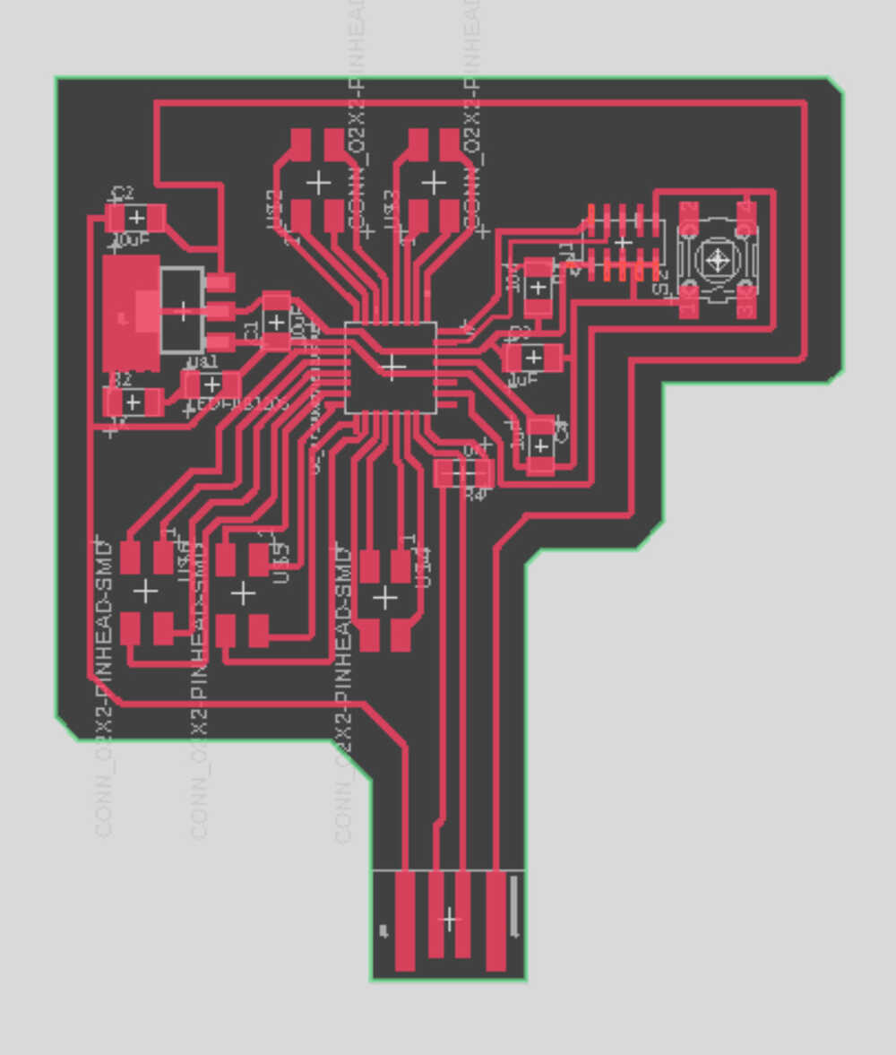
My pitch-matching is pretty experimental so I want to make sure I can change my circuit on the fly. Being able to mill my own circuits has been great, but it is a hassle to design and redesign a board because of a circuit error. That is why this time, I am going to mill a breakout board:
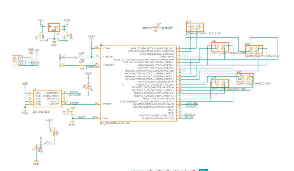
I had a pretty rough time soldering the tiny pins on the SAMD21E the last time I used it and was aiming to use an experimental board with less pins. However, after reading through some of the datasheets on the other boards, I realized that on the basis of using the board for experimental circuits and code as well as needing memory space for using serial connection, SAMD21E really was the best option... fine.
My last circuit board contained vias-- holes that went from the surface of the circuit board to the back of the board that were used to connect ground connections to the sheet of copper on the bottom of the board. Having to drill through the board really upped the mill time. The SAMD21E has 20+ usable I/O pins so I felt that the milling time would probably be too long if I had to drill a hole for all of them. This would especially become problematic if I had to print the board multiple times due to error. So, rather than include pins that go through the board, I opted for the 4 pin surface connectors. I also made sure that SWDCLOCK and SWDIO were tied to a connector pin and that RESET was tied to a button so the SAMD could easily recieve outputs from the bootloader and be manually reset.
milling.
sandpaper... it's very effective!
I uploaded my circuit as a gerber file to the Othermill. This week on the Othermill was a bit more difficult than other weeks. Generally, the Othermill setting are preset because a lot of people are doing the same board/ assignment. As we get deeper into the course, the similarities between the assignments each student does increases and that is reflected in the settings that they set on the machines that they use. All of this just means that attention to the settings of the Othermill was more important this week. I will list my steps below for future reference:
- To export a gerber file from Fusion:
- 1. Click on the manufacturing tab
- 2. In the manufacturing tab there is a manufacturing dropdown, click that
- 3. Select the export Gerber file option in the dropdown
- To load the gerber file onto the Othermill:
- 1. Enter the file directory and open folders until you get to the CAMOutputs/GerberFiles directory
- 2. Take the copper_top.gbr and profile.gbr files (also additional files if you have vias/holes)
- 3. Enter the copper_top file into the Top file input and profile file into the Outline file input
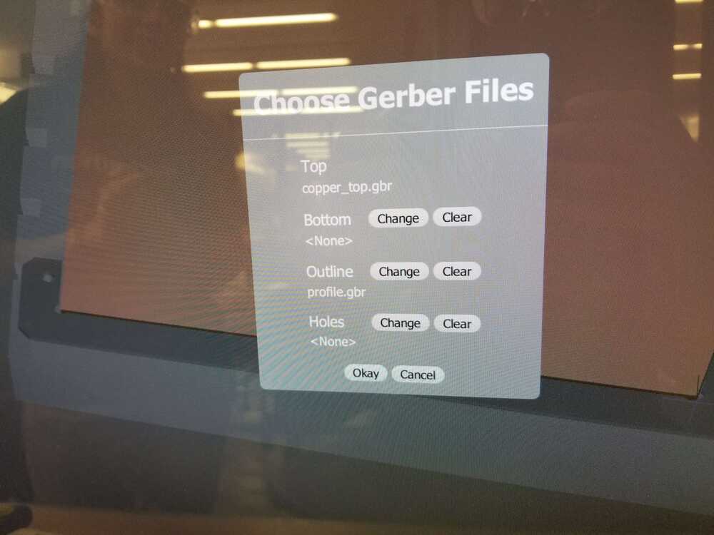
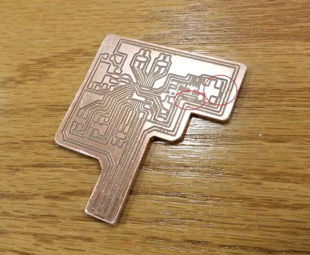
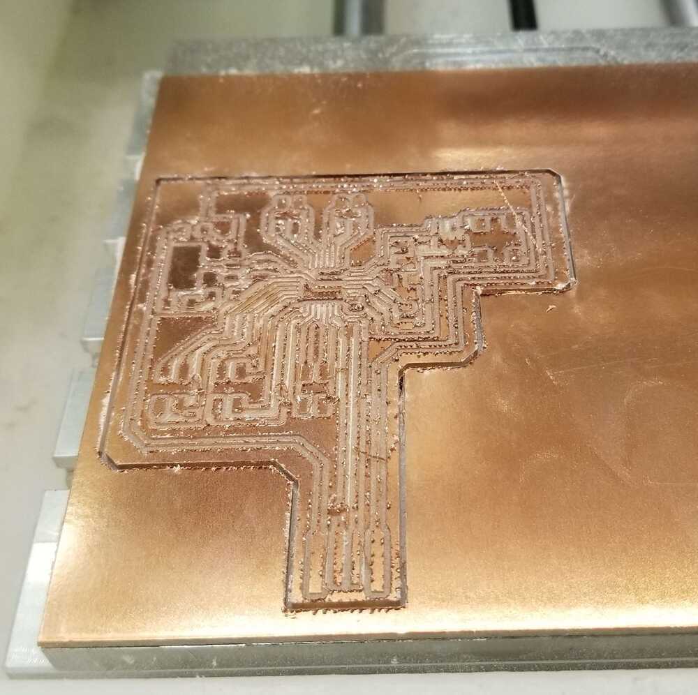
I followed these steps and while watching the mill run, noticed that it was completing very quickly. I attributed this to the fact that I had no holes in my design. However, after the milling process had completed, I looked at my circuit and found it to be very rough-- this was strange because the last time I printed a board, it came out pretty and smooth after all the copper shavings were vacuumed off. I went back to the Othermill and noticed that I did not change the drill settings to "PCB Conservative" (it got me! >:[ ). When setting up this print, I had to change more setting than usual since the person before me had changed most of the settings for their specific print. As noted before, I was used to starting my print after someone else who was completing the same assignment and wasn't used to having to consider every option since some would be preset.
I aggressively sandpaper-ed my board to see if it was salvagable. I was surprised that so many of the traces stayed on! In the past I was always nervous about sandpaper-ing my boards. I found the method that worked best was rubbing in small circles. Anthony told me after that using the painting-scalpel-looking tool we have in the lab to scrape the board parallel to the traces would have been faster and just as effective. Unfortunately for my first print, some traces did not survive, so I went to print again:
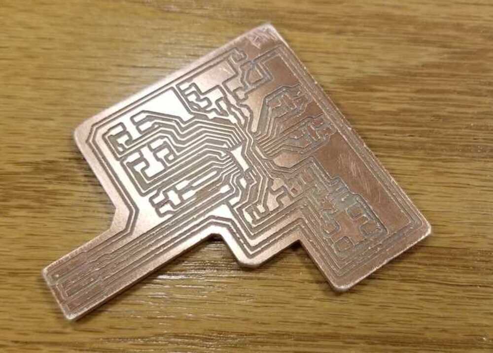
I printed again with the correct settings and the board still came out rough :(.
 After discussing it with Anthony, we figured that it must have been drill bit wear. To prevent future errors, I will add to my lists:
- Running the Othermill:
- 1. Confirm that the origin is in the location as displayed on the screen
- 2. Make sure to use "conservative" settings for drill bits
- 3. Make sure drill bit is not dull or broken
I scrubbed my second board with sandpaper and checked the traces under the microscope and with a multimeter. I decided to go ahead with soldering.
soldering
more soldering techniques
I made a lot of progress this week in terms of improving my soldering skill. I was able to put down the SAMD21E in under a minute... it was a spiritual experience. I will list some of the techniques I found were effective below:
- Soldering tiny pins:
- 1. Place the part
- 2. Touching the part with the gun or solder can (very annoyingly) launch it across the board so instead, head the copper right in front of the pin without touching the part
- 3. Place the solder on the copper between the gun and the pin so the solder flows under the pin, somewhat holding it in place
- 4. Now that the pin is partially glued in place, you can heat the pin directly and place solder on it
- 4.1. If step 4 causes the pin to dislodge, repeat the previous steps and instead of step 4, try to partially glue another pin down in the same manner before moving on to step 4
- 4.2. If the 4.1 solution is not working, apply some solder to the gun, and hold down the component with tweezers. First heat the pin, then flip the gun over to the side where the solder is and place that on the pin
microphones and speakers
amp it up.
My idea for this week is to use a contact mic/vibration sensor to pick up an intended frequency from a hum. This will go through the microprocessor, where the frequency will be isolated/ identified. The program will then take its guess and generate the frequency as a pure tone through an output-- a speaker.
The main issues with microphones and speakers that are connected to microprocessors are insufficient voltage and current. For instance, the sensor microphones generate a voltage/wave that the microprocessor reads; however, on it's own, the microphone generally produces such a small wave that the microprocessor misses the reading. Similarly, the microprocessor cant put out sufficient current to drive a speaker at a hearable volume. So, some sort of amplification both ways is required.
[week 8] let's start with the input.
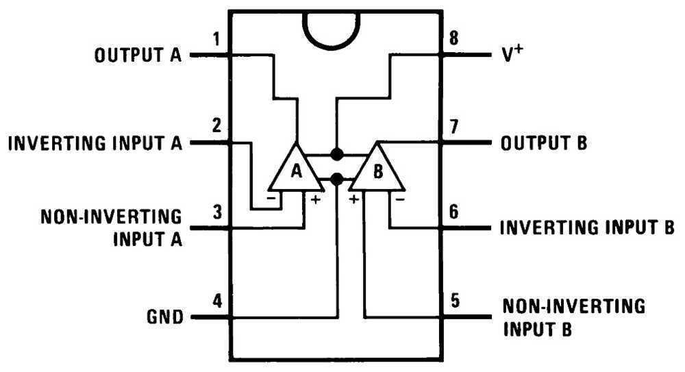
For the mic input, I want a voltage/wave amplification, but not a ton of current amplification since it is going into the microcontroller. I chose the familiar LM358 op-amp to accomplish this. The amplifier circuit is common so I found an example online:
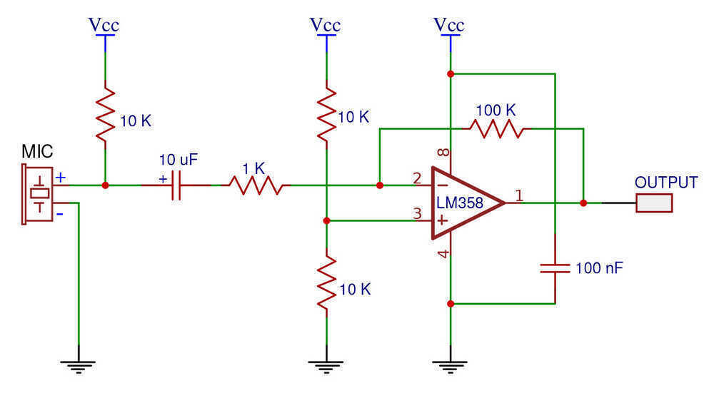
Since the output was going into an analog port on the SAMD21, I wanted to make sure that the input would not recieve higher voltage than the reference analog voltage 3.3V. To do this, I set the positive rail of the LM358 to 3.3V. The downside to this is that you generally do not hit the rail voltage of an op amp, so my voltage measuring range would be compressed.
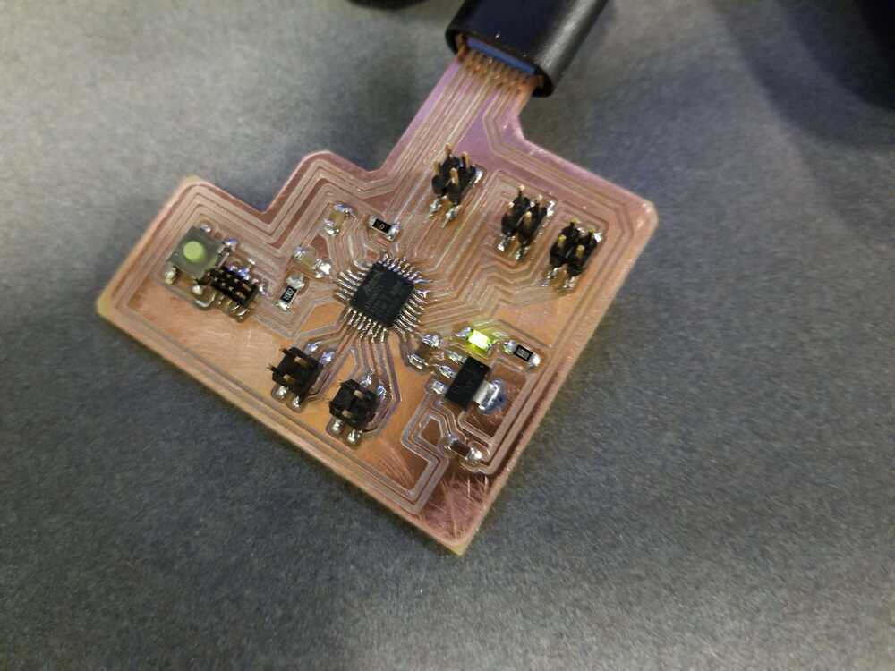
After programming my breakout board, I got a breadboard and some wires to create my circuit. Almost immediately, I realized that I should have created a ground pin when designing my board. The only pin outs were the digital and analog ports. To create a common ground, I had to set one of the digital ports to low and then wire that into the ground rail of the breadboard. It works, but took more time than it needed :/ .
I keep a lot of my old sensors so I had a couple mic options:
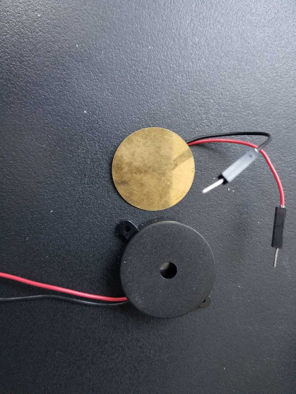 The gold sensor is a contact mic and the black sensor is a vibration sensor. These sensors function similarly: they translate vibrations they experience into voltage. I got the vibration sensor from the lab. Though the vibration sensor looks leagues better than the contact mic in terms of quality, I had a feeling (given my experience with contact mics used in live electronic music performance) that the contact was worth testing as a viable means of relaying the frequency of a surface it touches.
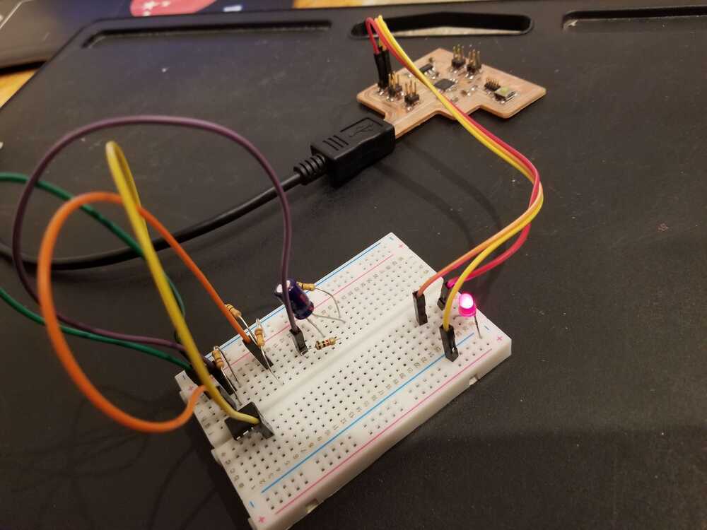
I set up the circuit with the contact mic first. I was debugging as I went using an led I had placed on the board. There are many pins coming out of the SAMD21, so after choosing a pin, I would generally test to see if my wire placement was correct by setting the pin high and sending it through an LED to see if it lit up. I repeated this process to check all of my input pins and then completed my microphone circuit:
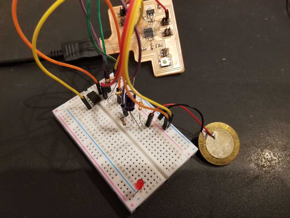
I created a basic program where I read the input values from the microphone and outputted them to the Arduino Serial Plotter. I held each mic to my throat and hummed a pitch. I took video of the responses:
This is the contact mic. You can see clear differences between when I am humming and when I am not. However, there is still a fair bit of noise. This is the vibration sensor. Like the contact mic, you can see clear differences between humming and silence. There is a lot less noise here too.
The vibration sensor seems to be the pick here. Regardless, I think I will keep the contact mic an option as I move to augment my testing apparatus to include output sources.
The next steps for testing the input would be trying to sample the frequency from the mic inputs. While there are likely libraries available that will do frequency identification for you, I feel that it may be necessary to make a custom system. The way I imagine things is that the user will press a button, hum a sound, and then release the button. This will give the arduino a timeslot in which to take samples. Based on the readings, sampling rate, and the time period in which readings were taken, you can calculate frequency. This is the basic solution. If necessary, I see myself exploring fourier transform algorithms. The frequency on the surface of the throat is not a pure tone, so various other frequencies will be mixed in with the target frequency-- this where I see the fourier transform coming in.
I leave the investigation of these options to future weeks since this apparatus could be important for my final project.
[week 9] let's add an output.
While I don't think output devices will be featured in my final project, I recognize their utility for debugging. I had two ideas this week for helpful outputs: an OLED and a speaker. So far, I have only been using Serial Plotter on Arduino for visualizing outputs. It is hard to look at other variables while also monitoring the Serial Plotter, especially when printing to the Serial causes it to scroll up very fast and makes it difficult to hang on to important values while seeing live outputs. Having an OLED would help with data visualization. Additionally, given that the output of my code will be the guess the circuit has for the frequency I hummed, it would be most helpful if I could hear the guessed frequency, rather than read its numerical value. That way, I could determine how correct the guess is using my ear while humming the correct pitch.
I wanted to do the speaker first, given that it was probably going to be the more useful of the two. For the speaker, I wanted voltage AND current amplification so I used an audio amplifier (LM386). The datasheet for the amplifier lists example circuits:
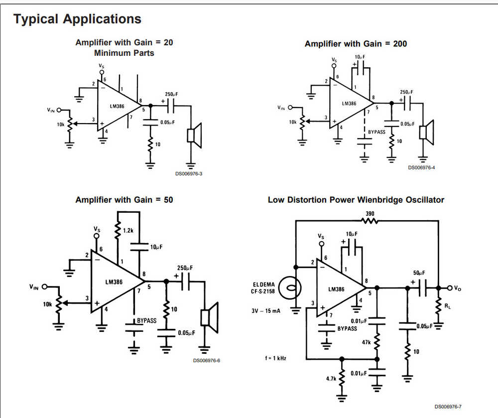
The amplifiers will only boost within the voltage rails they are given. I got a dc jack and a 12V power brick to power the amplifier (exciting!). I collected the circuit components, but later realized that I had collected the components for a different amplifier. Unfortunately for me, I realized this fact when I was working at home, without lab supplies. Guess I am saving the speaker for a later week :(
Thank God for back up plans -- it was time to hook up an OLED screen. Luckily, that was something I did have at home-- again, never throw anything away.
Let's try this again.
[week 9] let's pretend the OLED screen was the original plan :)
I thought the OLED screen would be an easy wire-up.I was wrong.
The first issue that came up was that the OLED screen required 5V to run. I had no pins for GND and 3.3V, so I definitely did not have one for 5V. I will have to include that on my next breakout board. Luckily, I have like 7 Arduino boards lying around in my house. Those boards have 5V pins :). In addition to my ugly wiring, I now had an entire Arduino connected to my circuit. It was not optimal, but it worked.
There is a library that is available for OLED screens that is commonly used when hooking the screen up to an Arduino. It references the SDA/SCL ports that are labeled on the Arduino. Rather than let you decide on which ports are SDA/SCL for general boards, the library (outside of the main file) defines them for you based on your board type. You also can't change these presets. Great.
Looking online, I learned about the TwoWire library which directly addressed this problem. After replacing the initializers in the example file for the OLED screen, I was able to get some outputs. That is all for these weeks assignments.In future weeks, I will move to implement the frequency finding code + speaker circuit!