Electronics Design
This week we had to design our own board that had the basics components plus at least an led and button. I decided to use the recitation video as a guideline for how to design my board and what components to include. Then I added the required led and button. After that I had to route all the parts together. This was the most difficult part to do.Board Schematic and Eagle
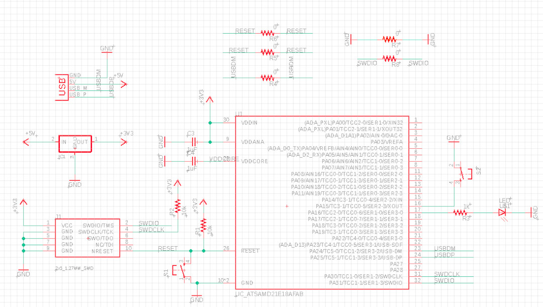
Because I had no experience with electronic design before, I had to learn how to use a design software first. I decided to follow the recitation video to learn Eagle. However the board it creates is different. I asked Anthony if using a SAMD21 chip was okay when the reference board uses a SAMD11. Since this board is just more powerful, he said it was okay so I kept using the same board and schematic as the reciation. I then also added a switch to pin 16 and a resistor plus a led to pin 17.
Once I was done adding all I needed to the schematic, I checked the connections with Anthony. Then I moved onto routing.
Routing
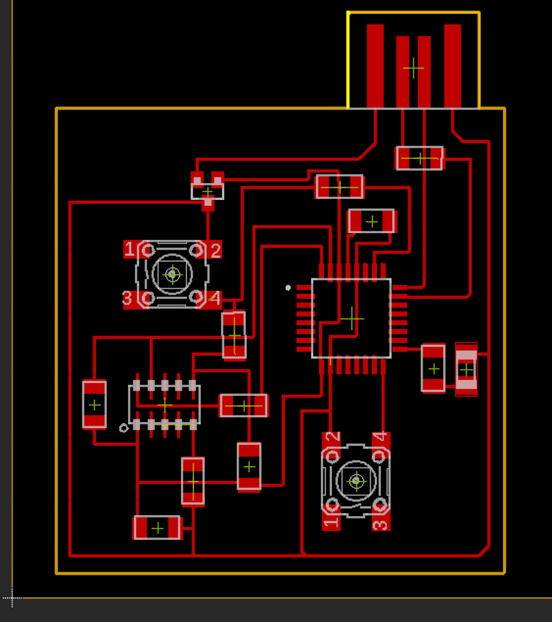
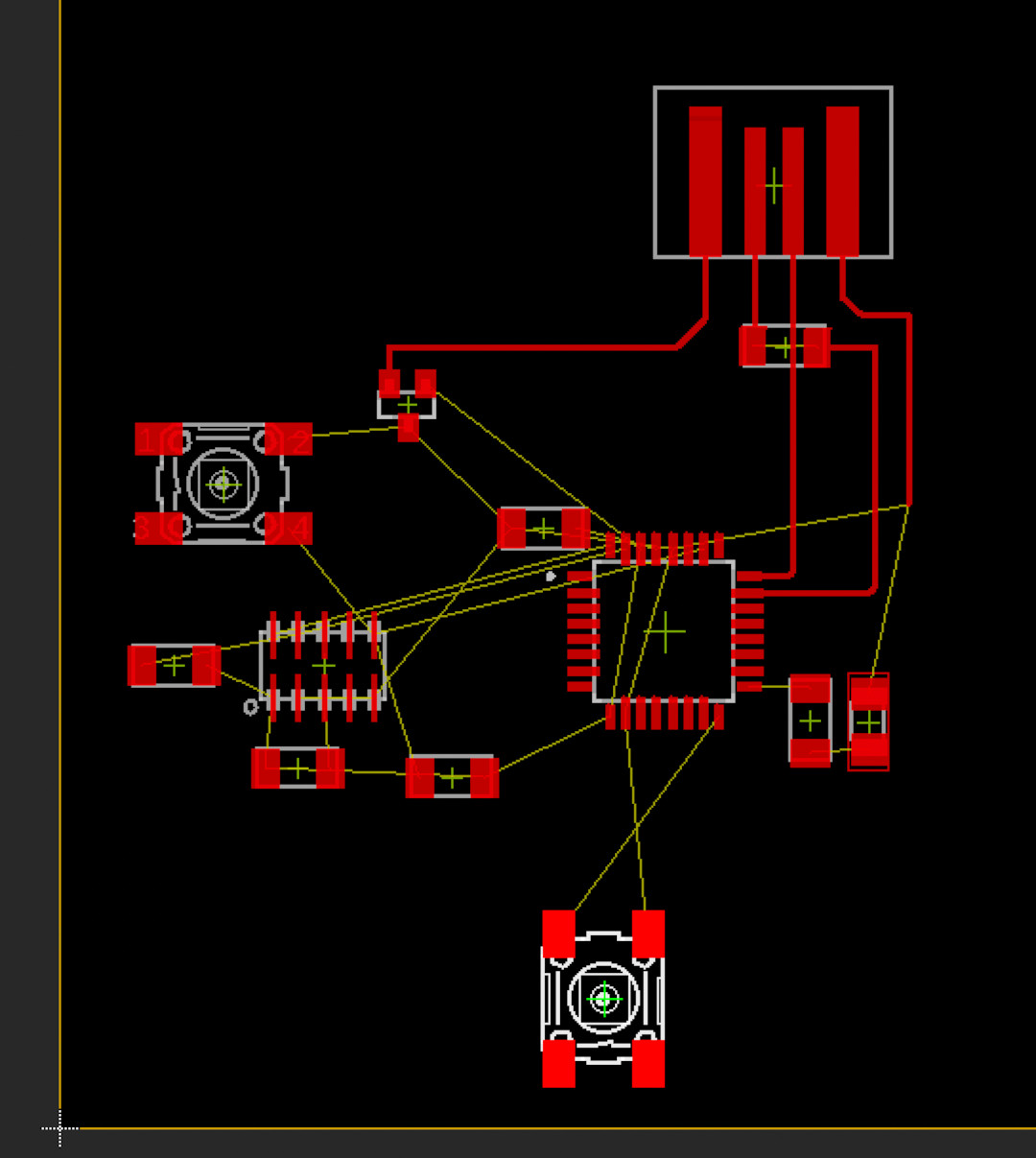
- I started routing by mushing parts together and drawing routing lines to connect parts to where they needed to be connected. I first connected the usb lines to the board. Then I placed the volatge regulator to the left of the usb so that the ground and 3V3 can wrap around the entire board.
- Then I started moving parts to surround the board. If they were connected to the bottom of the board, I moved them below the board and continued that pattern for the rest of the board.
- Once I had all the parts where they made the most sense, I starting adding more routes and seeing where I needed to add jumps.
- I added a jump for the USBDM wire because the board had the USBDM and USBPM wires flipped so there was no way to get around this.
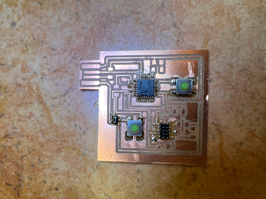
- Button and led were super simple to route because there was nothing in the way.
- The header was where things got interested. It was literally surrounded by resistors and a capacitor. I laid the resistors around the header as close to the side they connect to. However, no matter what I did, I had to use three jumps (resistors with value 0).
- Problem: I needed to get a wire beneath the header to connect to pins inside the header but I could not get it through no matter what I tried. It turned out I had a library that was outdated. I had to change the footprint of the header by moving the pads out a bit manually. Then I use an 8 mil width route to get under the header. This also proved to be very useful for routing underneath the main chip.
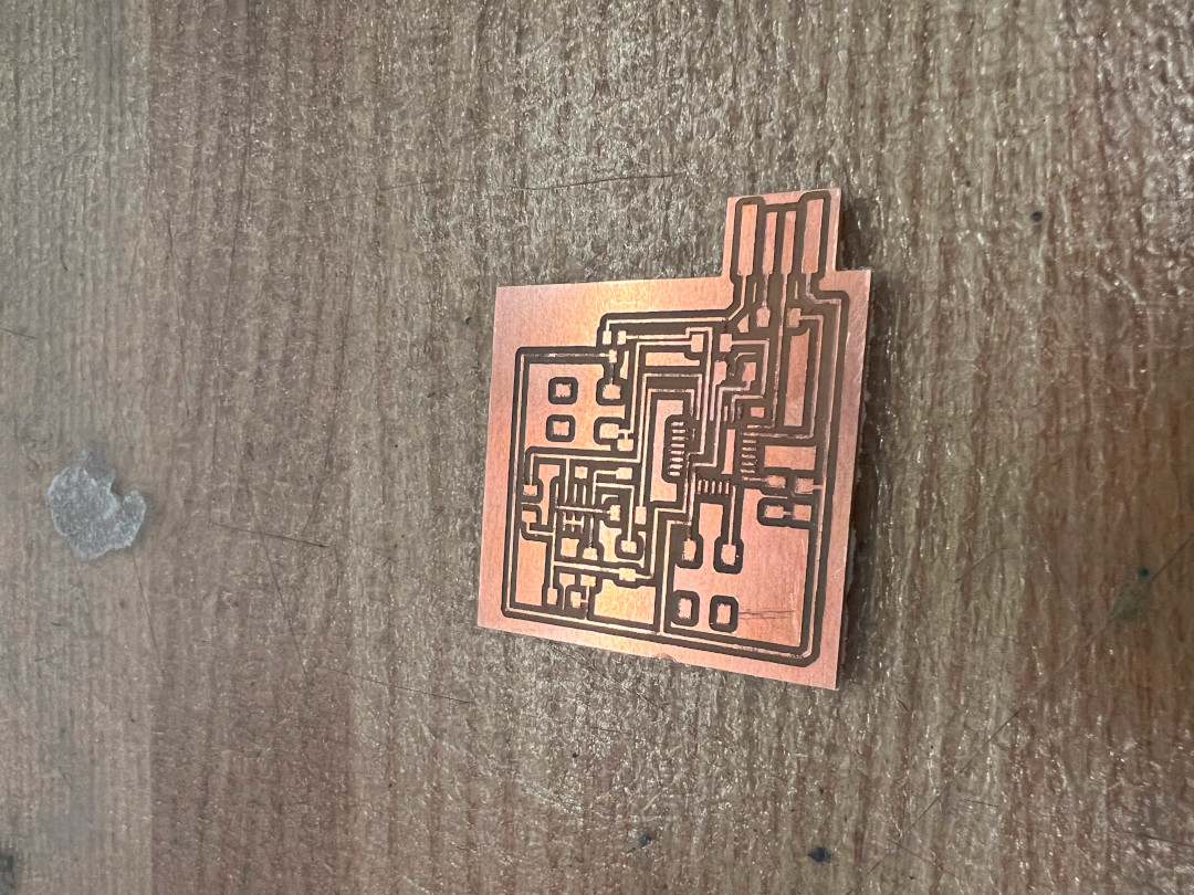
After I was satisifed with my routing. I used the Roland to mill the board. After I picked out the parts and soldered
some of them on.