Welcome to Blog Post!
Vinyl Cutting
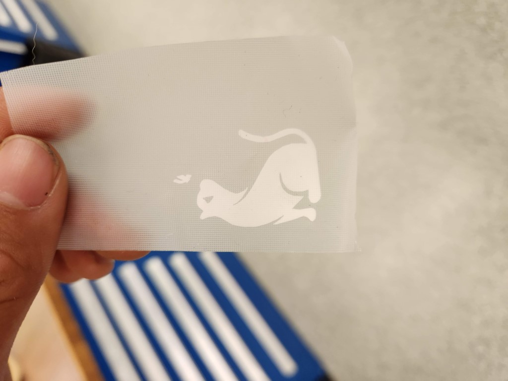
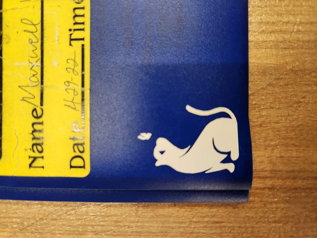
The vinyl cutter assignment went smoothly. I wanted to cut this cat with butterfly decal using the Roland vinyl cutter in EDS.
I loaded the image into the CBA vinyl-cut tool, which took care of the edge detection and pathfinding needed to produce the vinyl cut. I just had to set the DPI (dots per inch) to set how large the cut would be.

Using the vinyl cutter was pretty straightforward. Load in the vinyl, make sure that there’s vinyl underneath the two guide wheels, and hit play. After a few flukes where the cutter didn’t finish cutting the entire path, I finally got the cut!
Next was using transfer tape to lift the cut vinyl off the rest of the spool. I used a pair of tweezers to help peel the vinyl off better and remove gaps in the design.
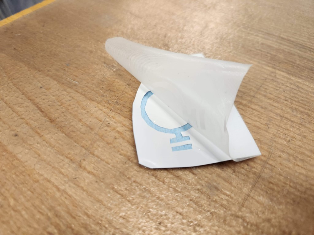
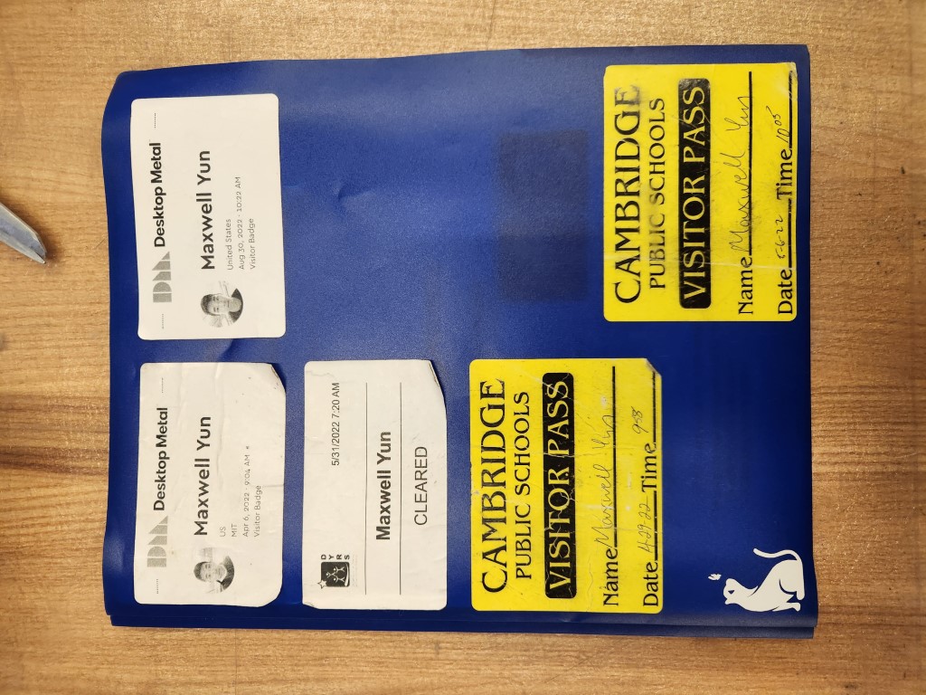
Finally, I transferred the vinyl from the transfer tape to my folder. I now have a cat with butterfly decal on my folder to make it mine!
CAD for laser cutting
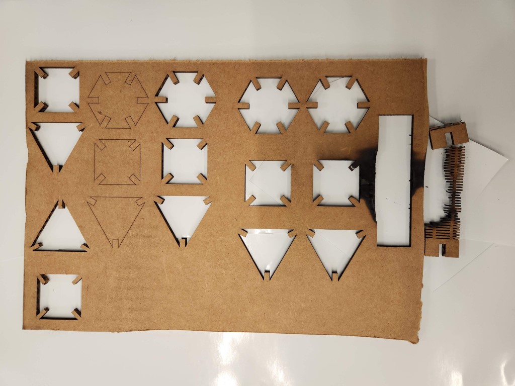
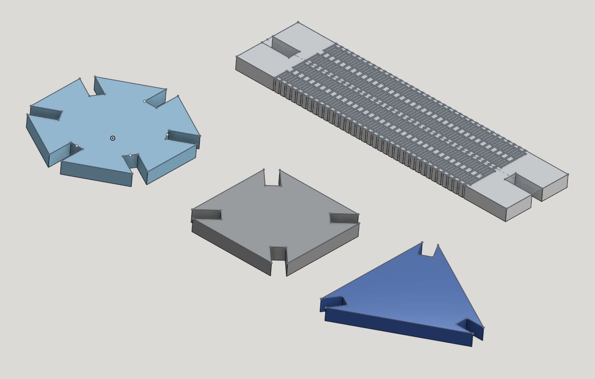
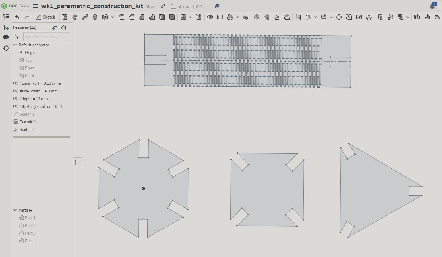
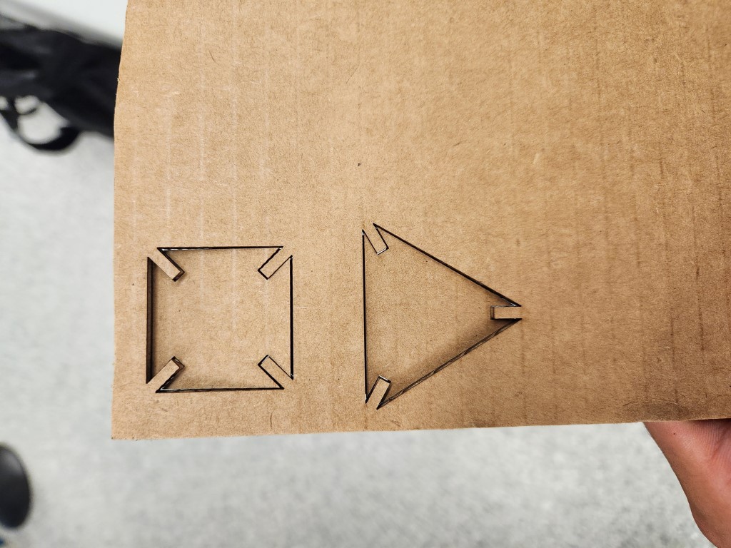
I designed a modular kit that’s intended to be laser-cut out of cardboard, and can be assembled by hand. The kit includes hexagonal, square, and triangular elements that have notches cut out of them, so that they can interlock and be built into any shape.
The CAD accounts for a few factors. First, the width of the cardboard stock itself determines how wide the notches should be. Also, the kerf of the laser beam is critical. The kerf is the width of the laser beam itself; when the laser cuts it “burns off” that width of material. It’s a small number like 0.1mm, but that’s the difference between if something press-fits nicely or is too tight/too loose.
I also attempted to design a flexible linkage using a “living hinge”. The “living hinge” has an intricate network of small cuts embedded in it, allowing the cardboard to be flexible. This design worked out in CAD, but not in the actual laser cutter itself.
One thing I forgot to include in the CAD was a chamfer in the notch. The chamfer rounds off the corners at the top of the notch, helping pieces slide in together better. For future designs I’ll include the chamfer.
Laser Cutting
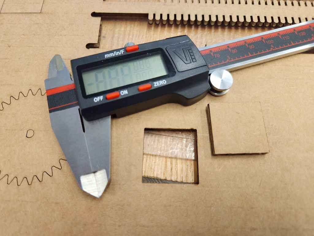
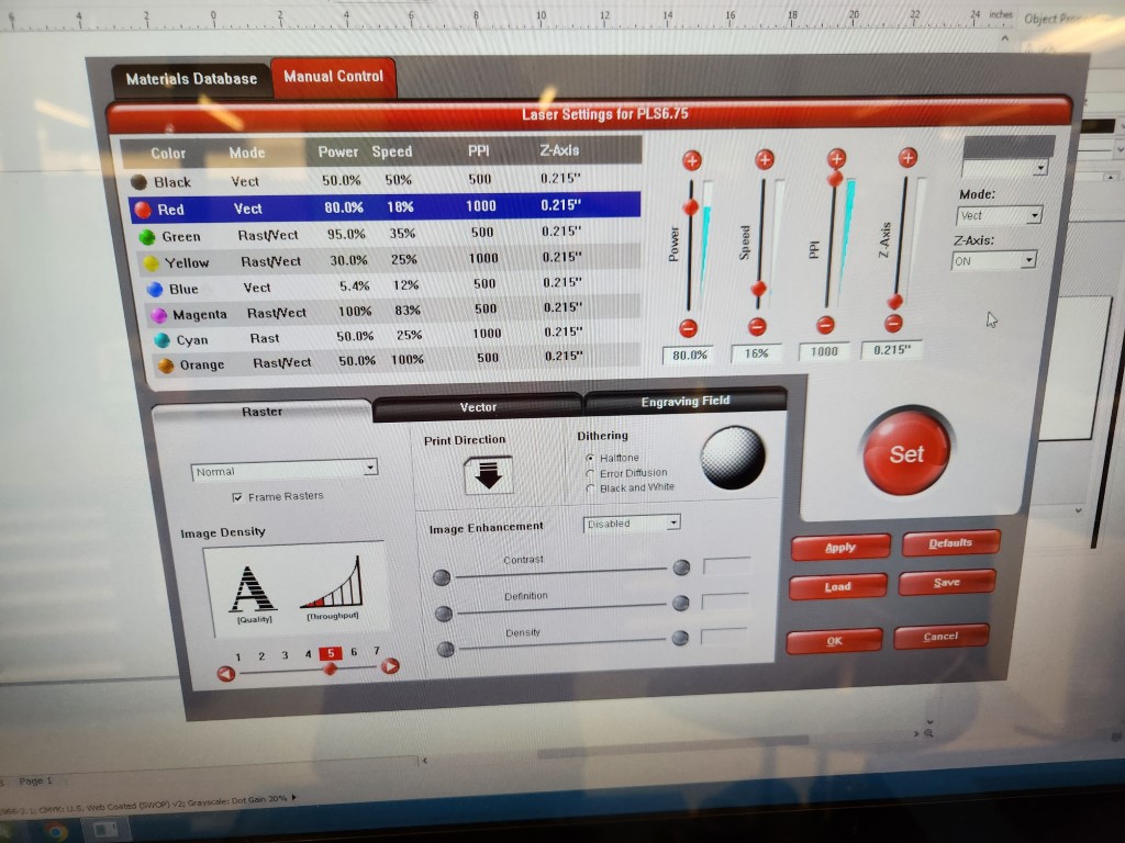
To laser cut, we first had to calibrate the laser power. There are two key parameters: laser power and speed. Too low power/high speed will not cut fully through the material, and too high power/low speed will burn the cardboard… like, set it on fire. There’s a happy medium setting where the laser cuts perfectly. This required cutting numerous test squares out of cardboard and finding the ideal spot where the laser just pierces the cardboard.
We then measured the kerf of the laser by cutting one-inch by one-inch squares out of the cardboard, and measuring the cut square’s exterior dimensions versus the opening’s interior dimensions. The difference between the two, divided by two, gives the width of the laser beam itself. I measured that to be 0.103mm.
Also, the laser focus is another critical setting. The laser beam diverges slightly, and an out-of-focus laser beam can make wider kerf than is necessary. To make sure the laser beam is in focus, I had to use a calibration tool to ensure the laser beam is a set height above the cardboard stock.
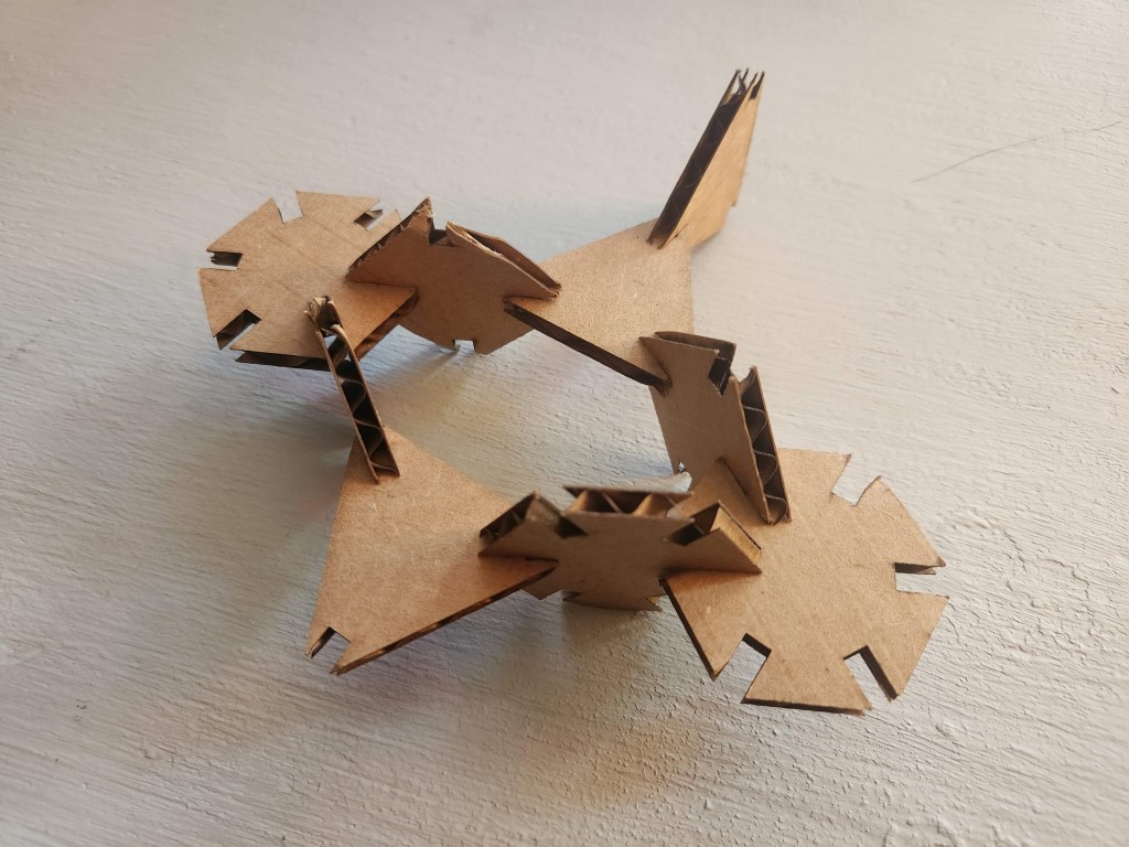
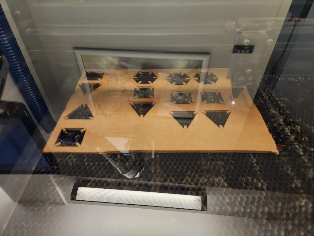
With these calibration settings, cutting the shapes was pretty straightforward. I had to do some CAD fine-tuning of the notch width to get the pieces to fit nicely together. But lo and behold, I had some ready-to-use pieces in my hand!
The flex beam didn’t go so well. The gaps I designed were only spaced 0.5mm apart, cutting it close to the 0.1mm kerf of the laser. The features were placed too close together for the laser to comfortably cut. As such, the flex beam actually caught on fire when I was trying to cut it. I put the fire out and reported the (minimal) damage, but the piece was gone. I’ll have to re-design the flex beam with farther spaced apart features for it to be manufacturable.