Input and Output Devices... and Bike Lights
Nighttime visibility is very important when biking – not only do cyclists need to see the road ahead, but cars also need to see the cyclists. Bike lights are great for this, but they need to be turned on/off and need to be recharged. I figured why not integrate this with my e-bike project, and have auto-switched lights… with a little special something!
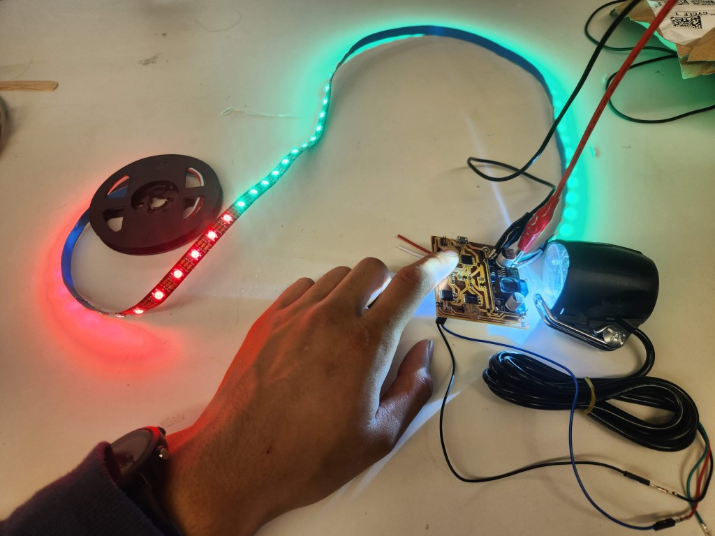
This project combines Weeks 9 and 10, the input and output modules. My input is a phototransistor that senses the ambient brightness, and my outputs are bright LED’s driven through MOSFET switches, as well as a RGB LED strip!
PCB Design and Fabrication
I designed a custom PCB in KiCAD for this week’s project. In past weeks we used the ATSAMD11C microcontroller because it’s smaller, cheaper, and easier to solder. However, this week’s project is a bit more demanding on the microcontroller because of the RGB LED strip. I need a bit more program memory to be able to use the NeoPixel (LED strip) library, so I decided to upgrade to the larger, more powerful ATSAMD21 microcontroller.
Drawing the schematic was fairly straightforward. I copied the SAMD21 implementation from the HTMAA website, including the programming header and power regulator. I added MOSFETs to drive the headlight and taillight, choosing a two-stage design where a smaller MOSFET drives a larger MOSFET because I wasn’t sure the larger MOSFET could be driven by the logic pins. This means that the logic is inverted for driving the lights; pulling the smaller MOSFET’s gate LOW turns on the light, and pulling the gate HIGH turns off the light.
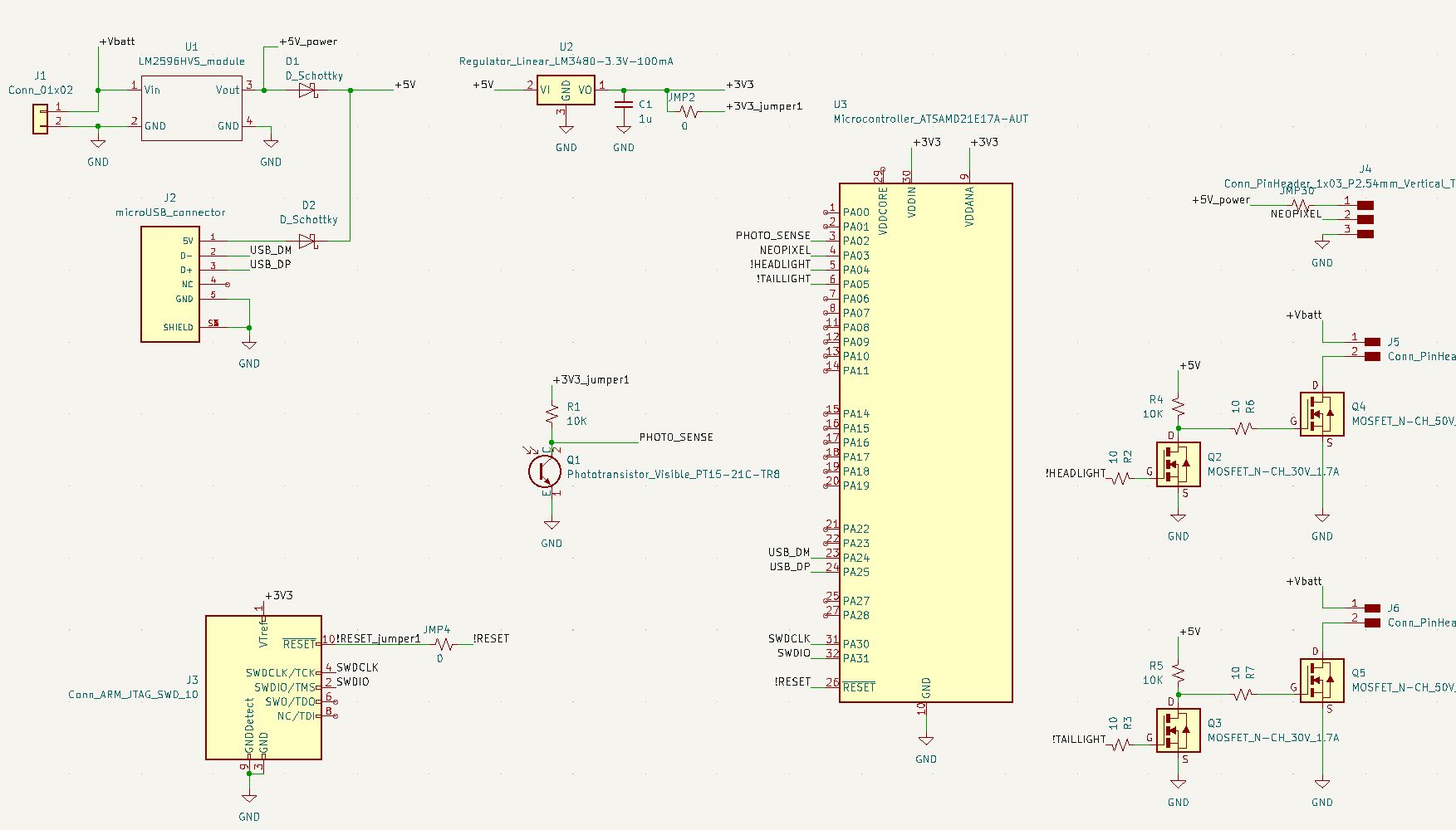
I also used a buck converter that steps down battery voltage (~42V) to a more reasonable 5V. It’s a module I bought off Amazon that takes in up 60V and outputs 3A. It uses the LM2596HV buck converter IC to do its magic. The board logic has to be able to run off the buck converter or the USB connector; I added some diodes from each source to enable this. I had to measure the dimensions of the board and the location of the mounting holes for the design. The buck converter module lives on the top half of the PCB.
Laying out the PCB was a challenge, as all of the traces have to be on the same side of the board as single-sided boards are much easier to machine. Also, the traces have to be spaced far apart, as the machine’s endmill can only cut things larger than 1/64”. For example, the left board was non-machinable (pay attention to the bunched-up traces in the bottom) but the right board was the final board we made.
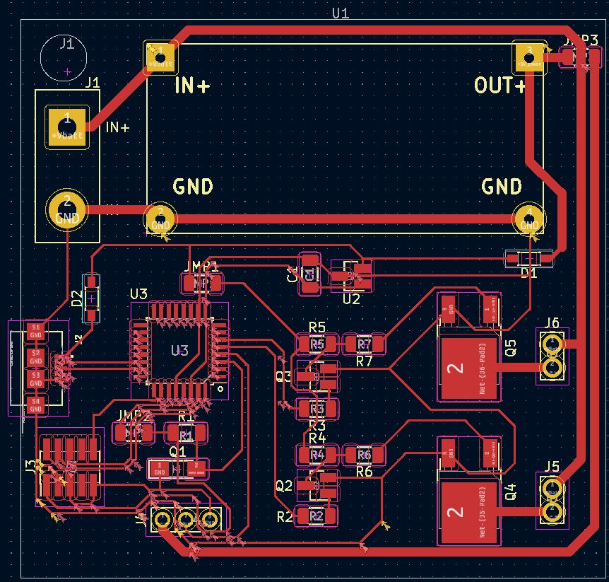
Unmachinable PCB layout
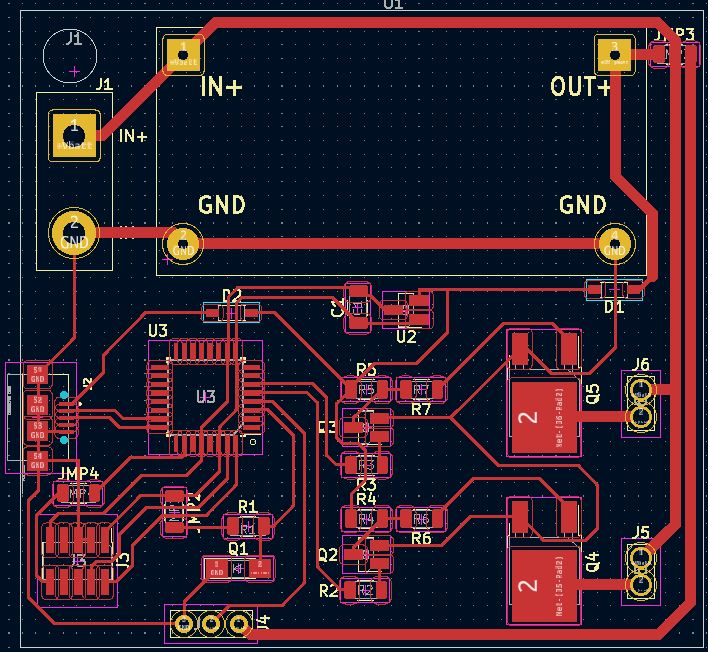
Good PCB layout
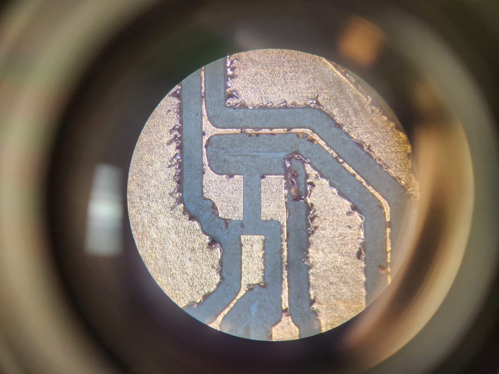
With the board designed, I exported a set of Gerber files and sent it over to the Othermill to be made. The Othermill did a merely passable job with my board, as I think I used an endmill nearing the end of its life. The edges weren’t cleanly machined, leaving raised edges. The traces weren’t uniformly thick. In some cases copper was not fully cut out, requiring I “post-process’ remove the copper with an X-Acto knife. Also, the spacing between the pads on the MicroUSB connector were too close for the Othermill, so I had to manually cut apart the pads with an X-Acto knife.
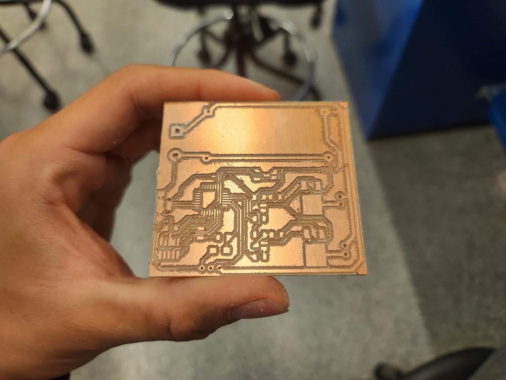
Assembly was smooth, parts soldered on without any issues or hesitation.
PCB Programming
I wrote an Arduino sketch that auto-switches the lights on/off depending on the ambient lighting. Note the inverted logic for turning the headlight/taillight on/off. Fortunately, interfacing with the ATSAMD21 microcontroller is very similar to the smaller ATSAMD11C chip.
#define PIN_PHOTOSENSE 2
#define PIN_NEOPIXEL 3
#define PIN_HEADLIGHT 4 // inverted output
#define PIN_TAILLIGHT 5 // inverted output
#define NUM_PIXELS 60
#define LIGHT_THRESHOLD 800 // will need to fine tune this one
Adafruit_NeoPixel strip(NUM_PIXELS, PIN_NEOPIXEL, NEO_GRB + NEO_KHZ800);
void setup() {
// put your setup code here, to run once:
// pinMode(PIN_PHOTOSENSE, INPUT);
pinMode(PIN_NEOPIXEL, OUTPUT);
pinMode(PIN_HEADLIGHT, OUTPUT);
pinMode(PIN_TAILLIGHT, OUTPUT);
digitalWrite(PIN_HEADLIGHT, HIGH);
digitalWrite(PIN_TAILLIGHT, HIGH);
strip.begin();
strip.show();
Serial.begin(9600);
}
void loop() {
while (true) {
int val = analogRead(PIN_PHOTOSENSE);
//Serial.println(val);
if (val > LIGHT_THRESHOLD) {
digitalWrite(PIN_HEADLIGHT, LOW);
digitalWrite(PIN_TAILLIGHT, LOW);
colorWipe(strip.Color(255,0,0), 50);
colorWipe(strip.Color(0,255,0), 50);
colorWipe(strip.Color(0,0,255), 50);
}
else {
digitalWrite(PIN_HEADLIGHT, HIGH);
digitalWrite(PIN_TAILLIGHT, HIGH);
colorWipe(strip.Color(0,0,0), 50);
}
delay(1);
}
}
void colorWipe(uint32_t color, int wait) {
for (int i = 0; i ;lt; strip.numPixels(); i++) { // For each pixel in strip...
strip.setPixelColor(i, color); // Set pixel's color (in RAM)
strip.show(); // Update strip to match
delay(wait); // Pause for a moment
}
}
Troubleshooting
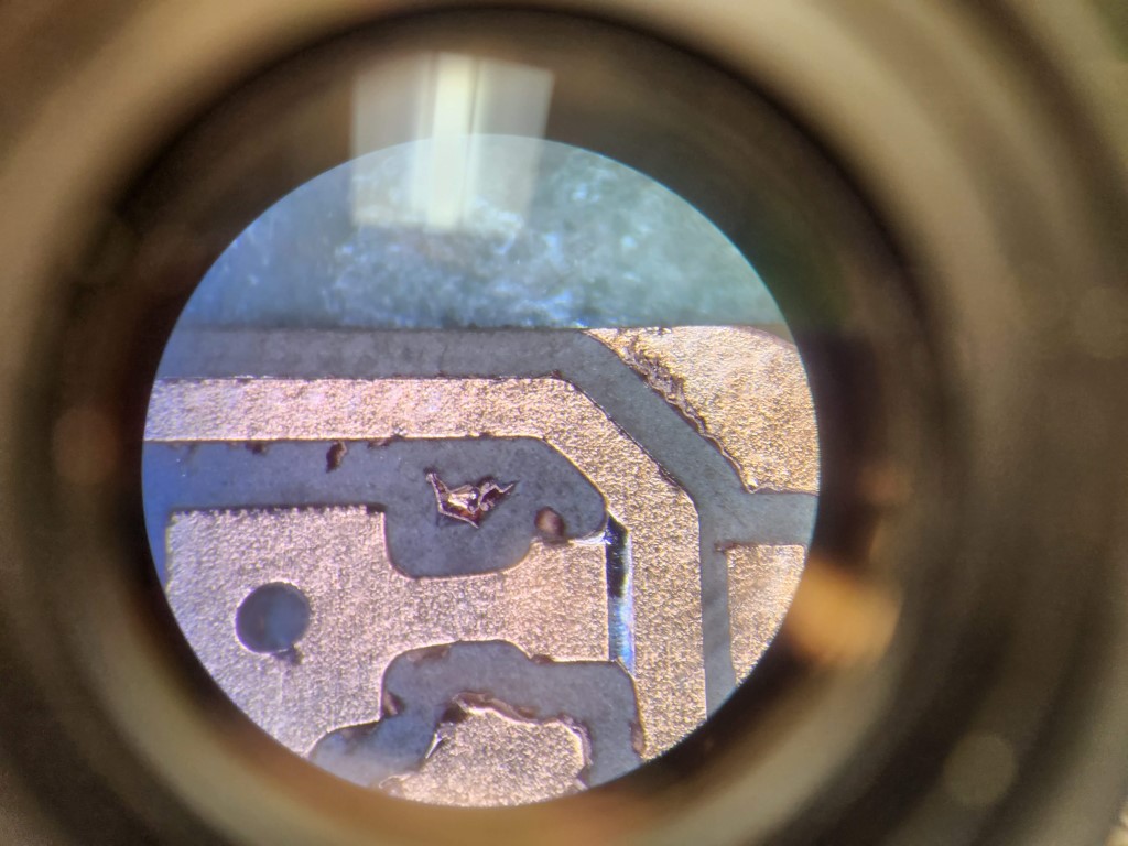
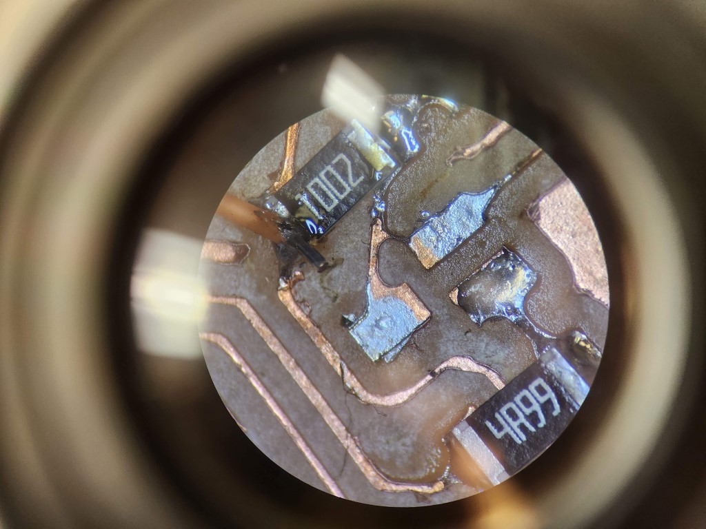
I had a lot of issues with how the board was fabricated. For one, the traces were not well milled out on the board, and I located and had to fix a few short circuits. Some traces were also damaged or extremely fragile at two locations on the board, requiring soldering jumper wire to bridge over the flaws. But nothing beats troubleshooting why my USB port didn’t work, which turned out to be because I wired the USB pins to the wrong pins in the schematic. Instead of connecting to pins 23/24 on the IC, I connected to pins 22/23 because of reading the datasheet wrong. Huge thanks to Anthony in EDS for helping troubleshoot all these board mishaps.
Conclusion
This really put into perspective the effort designing something as mundane as a Lego. We expect our parts to slide together perfectly and feel nice while doing so, without realizing the effort that goes into designing these features.