Final Project: Building a Derp-e-bike!
I like bicycles. I also like electronics. Why not combine both interests and build… an electric bike!
Electric vehicles are the future, so I’ve been slowly building my fleet of sketchy electric vehicles. I started off building two sketchy electric scooters, or rather, upgrading two crappy electric scooters with modern technology to go faster and longer. I’ve put hundreds of miles on both scooters, and they’ve mostly held up quite well! The next step is to take on a larger challenge and… build an electric bike!
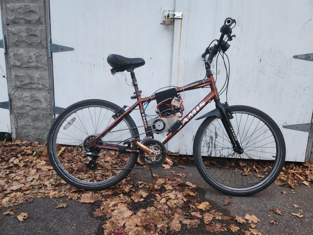
For this project, I’ll be retrofitting an existing bike with an electric motor in a “pedal-assist” configuration. This means that you can run the motor while pedaling to get a nice torque boost, and go faster with less effort than pedaling alone. For now, the motor is controlled via a twist-throttle, just like on a motorcycle.
My e-bike has the motor mounted in the middle of the frame. The motor drives the rear wheel through a second chain that attaches to the rear cassette, or cluster of gears mounted on the rear wheel. The original chain, between the pedals and the rear cassette, is still attached. Thus, when the pedals turn, the motor also turns. When the motor turns, the pedals are also spun. Not ideal, but a tradeoff that I’m happy with.
For this project, I’ll be retrofitting an existing bike with an electric motor in a “pedal-assist” configuration. This means that you can run the motor while pedaling to get a nice torque boost, and go faster with less effort than pedaling alone. For now, the motor is controlled via a twist-throttle, just like on a motorcycle.
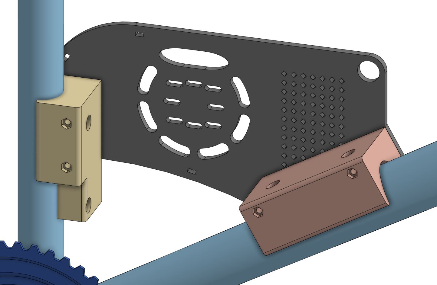
How are we mounting all this gear on the bike? The battery enclosure clamps the top tube in a custom-designed box. The motor is mounted on a plate that then screws into two blocks, that then bolts to the bottle holders on the bike. The motor chain goes around the largest sprocket on the rear cassette, and the pedal-driven chain is still shiftable through 5 of the remaining gears. There’s another recent addition, the motor chain tensioner, that mounts on the rear tube on the bike and applies spring-loaded tension to the motor chain.
Overall, the process took several steps. First, the actual bike had to be designed in CAD (computer-aided drafting) software, yielding a digital model that tries to perfectly replicate the real bike. Then, the accessories have to be designed on top of the bike. Then, we have to make everything and hope it fits together, or go back to the design stage.
CAD’ding the bike
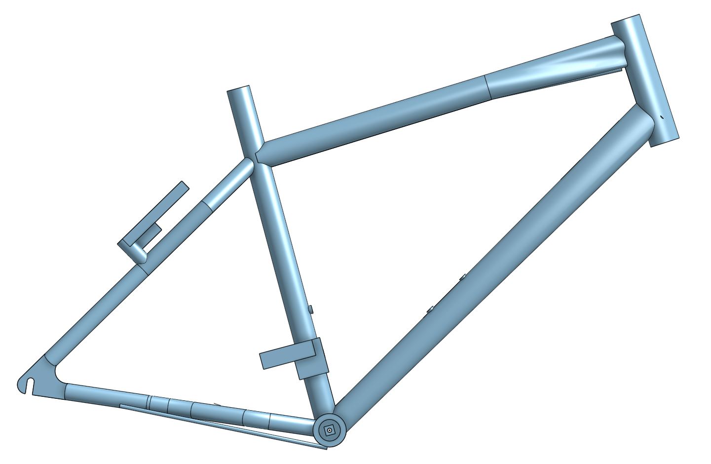
Designing the bike involved taking a lot of measurements and drawing everything into my CAD program, OnShape. Every painstaking detail, from the length of the downtube to the curvature of the top-post, needed to be measured directly, or drawn as close to the actual thing on the bike.
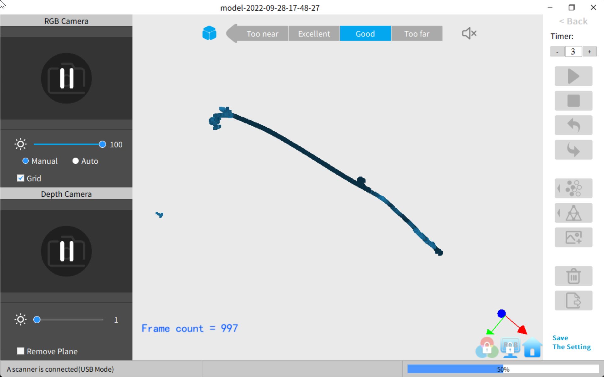
I attempted to do a 3D scan of the bike to make my life a bit easier. Instead of using a tape measure, what if I could simply click between points to get a true-to-life measurement? Using a RevoPoint Pop 2 3D laser scanner, I got… very subpar results. I think it’s because the bike is way larger than what the scanner can scan, as well as the fact that the bike is slightly reflective.
I got to business using a trusty tape measure and calipers. The difficult part of designing a modern (~2008) aluminum bike is that the tubing has non-circular cross-sectional profiles, which was a pain to measure and draw out. If you slice the tube in half and trace out the outline of tube, that’s the cross-sectional profile. This was particularly true for the downtube and top tube, which are funny shapes instead of simple and cylindrical. This might have been easier had I used a steel-frame bike with cylindrical tubing, but I also wouldn’t have learned as much about CAD.
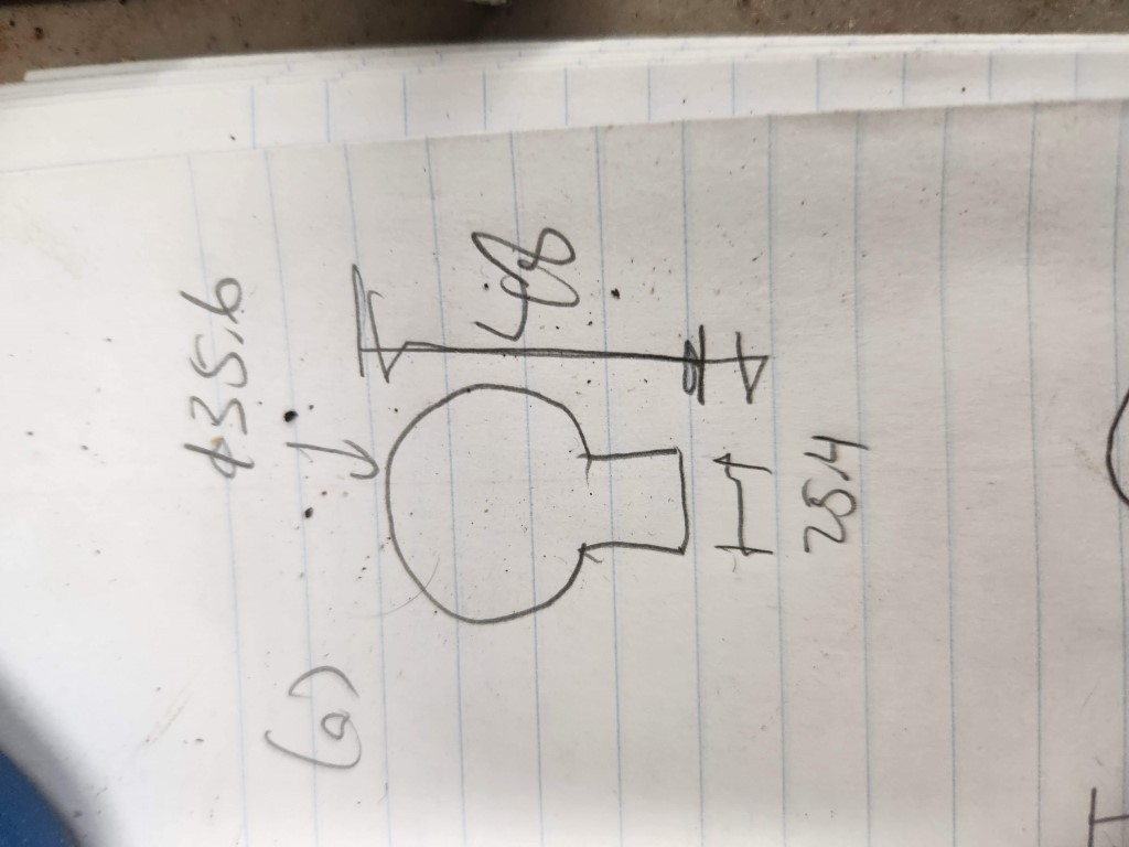
Sketching out the cross-section of the top tube
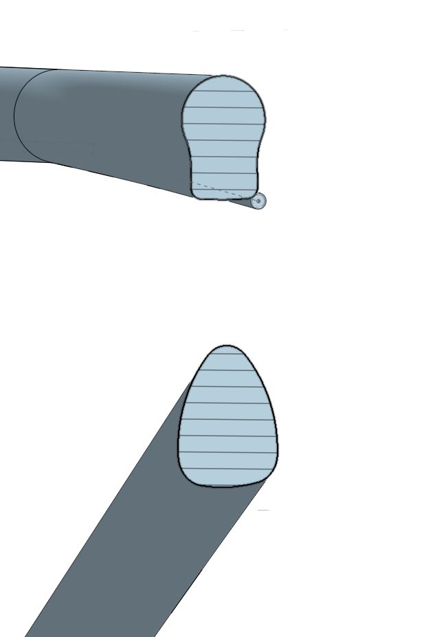
Non-circular cross sections of top and down tube
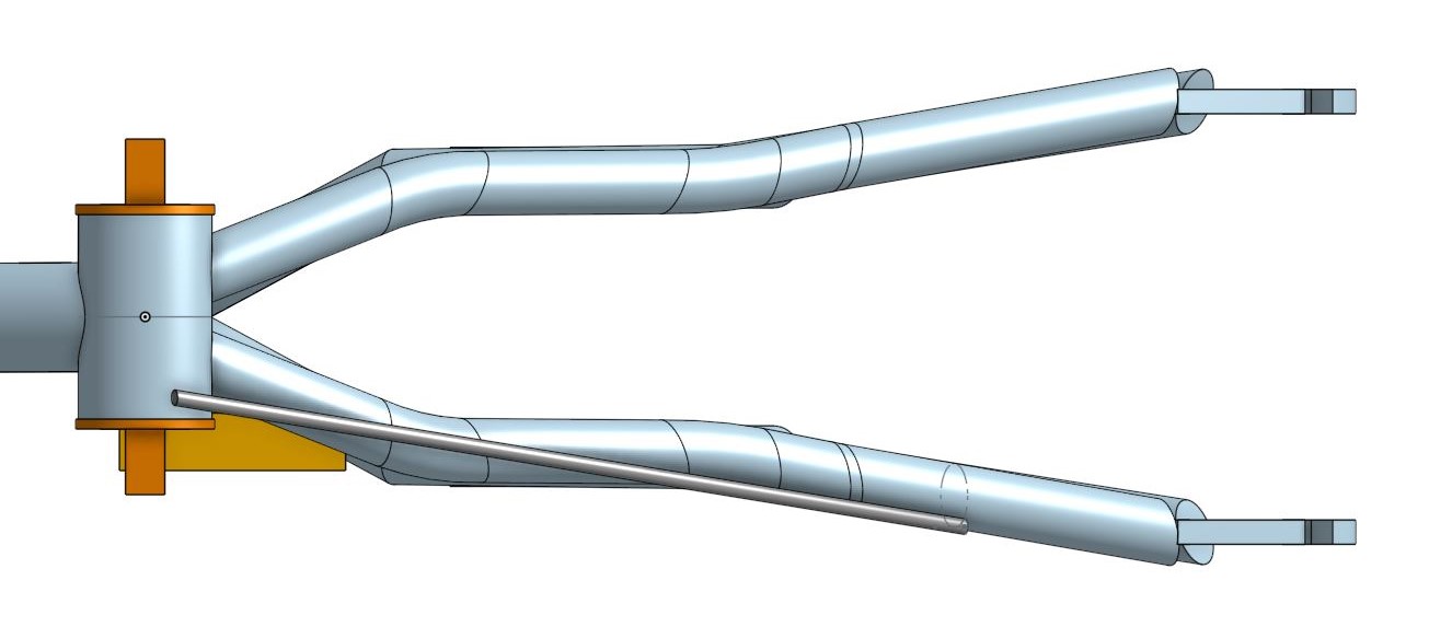
Also, the rear triangle has a lot of kinks in it. I designed this by measuring out the width of each section of tubing, then drawing connecting lines between the segments. I then drew the cross-section of the tube and swept it across the lines I just drew to get the desired shape. The end result is this.
Another thing that needed to be modeled was the cables that ran throughout the bike. This is important because some of my parts clamp around the frame of the bike, and it’s imperative they don’t pinch the cables. I modeled this by running tubing alongside the bike where there’s tubing.
I also needed to take into account the parts of my bike that my parts couldn’t obstruct, like the brakes or the front shifter. I designed those as simple rectangles that designate “keep-out zones” where my parts couldn’t obstruct.
CAD'ding the stuff that bolts onto the bike
With the bike designed, the next step is CAD’ding the parts that bolt onto the bike – the motor mounts, battery box, and tensioner. Here, it was critical that the parts fit perfectly, even around the non-circular profile of the bike frame.
This part was a two-step process – I’d first design the part, then I’d test-print it in low quality to see if it’d fit on the bike. Then I’d make observations like “the radius of this curve is too large, so it’s not touching the bike all the way through” and update the part with these changes. With the non-circular profiles of the bike frame, namely on the downtube, this took some more trial and error than expected.
With the motor mounts fitting nicely against the bike, I designed the backplate that holds the motor and motor controller. One feature I needed was the ability for the motor to tension the chain and absorb some slack, so I designed the motor to be mounted in slotted holes that allow the motor to slide back and forth. I added some vent holes for the motor and motor controller, and even some zip-tie holes for cable management.
Motor mount plate
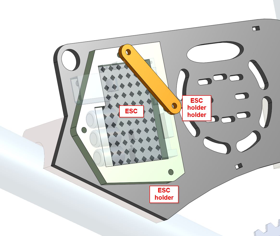
ESC mount on the motor mount plate
The battery box was pretty straightforward to design, although I took extra steps to make it fancy. The box is a three-piece design where the top and middle pieces clamp around the bike’s top tube, and the bottom piece carries the batteries and assorted electronics. The bottom and middle pieces zip tie together, so I added some zip tie holders to the part. There’s also a cutout for the brake cable and holders for the battery management system (BMS) and assorted connectors coming from the batteries. I added some rad graphics on the side of the box for extra visual pizzazz!
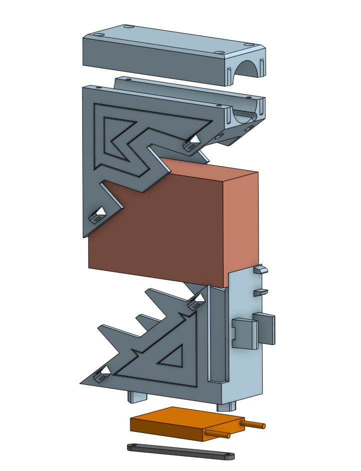
Exploded view of battery assembly
Far later into the design, I designed a chain tensioner to keep the chain tight. The tensioner would push an “idler sprocket”, or sprocket that’s designed to spin freely, into the chain using force from a spring. The tensioner would clamp onto the rear triangle of the bike. Remember how I mentioned the rear triangle has weird curves? Right, time to design around that. It’s also a feature, as the curves would help hold the part in place, or so I thought.
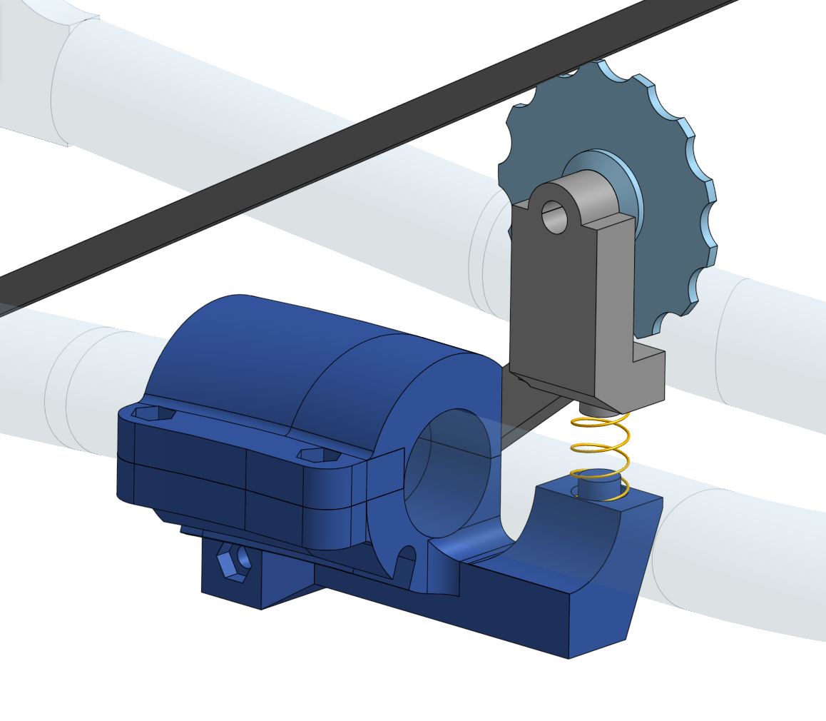
Tensioner close-up view
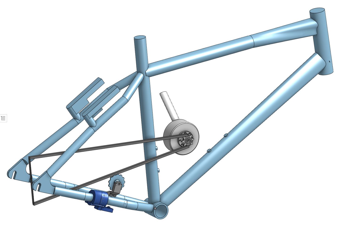
The tensioner on a simplified view of the bike
One challenge was aligning the sprocket to the chain. This took multiple adjusted versions, and multiple prints, to get right. The other challenge was designing the clamp to fit perfectly around the curved section of tubing on the bike. That also took some trial and error to get right.
As with before, I printed some “test pieces”, then adjusted my bike model to account for the fit issues. In particular, I initially designed too sharp of a curve in the rear of the bike, and my test pieces wouldn’t fit at all. I had to widen the curve on the bike to make it work.
Now with everything designed, how do we manufacture it all?
Making things!
For the test-fit prints, I printed in PLA on the Monoprice MP Delta Mini 2 printer that I have at home. It prints very fast (parts done in ~2 hours) and lives at home, so I could iterate quickly.
For actual parts, I printed in ABS plastic on the Stratasys J750 printer at the Cypress EDS shop. I chose ABS as a material because it’s more durable and UV-resistant than PLA. The Stratasys J750 also simultaneously prints a support material alongside the ABS; this makes the part more dimensionally correct. The support material dissolves in a sodium hydroxide bath, yielding a very nicely printed part!
The battery box I printed in PLA on the Sindoh 3D printers at EDS, because that was what’s available at the time. The print was a 29-hour print due to the size of the battery box, and fortunately it worked the first try.
For the backplate, I waterjet it out of aluminum sheet stock. Before doing that, I cut some test pieces out of cardboard on the laser cutter, to make sure the screw holes line up. Then, I first waterjet it out of 1/8” aluminum (pretty thin stuff) – in fact, the aluminum came from the side panel off an old Mac desktop, and I kept the Apple logo on my part! This turned out to be too thin, as the part bent under the torsional forces from the motor. I re-cut the part out of 1/4" aluminum, and have not had any issues with the new part! Thanks to Dave Preiss and Gregory Xie for helping me waterjet the parts.
As with before, I printed some “test pieces”, then adjusted my bike model to account for the fit issues. In particular, I initially designed too sharp of a curve in the rear of the bike, and my test pieces wouldn’t fit at all. I had to widen the curve on the bike to make it work.
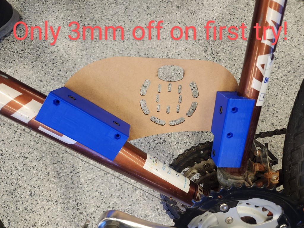
First test-fit of the printed + waterjet pieces
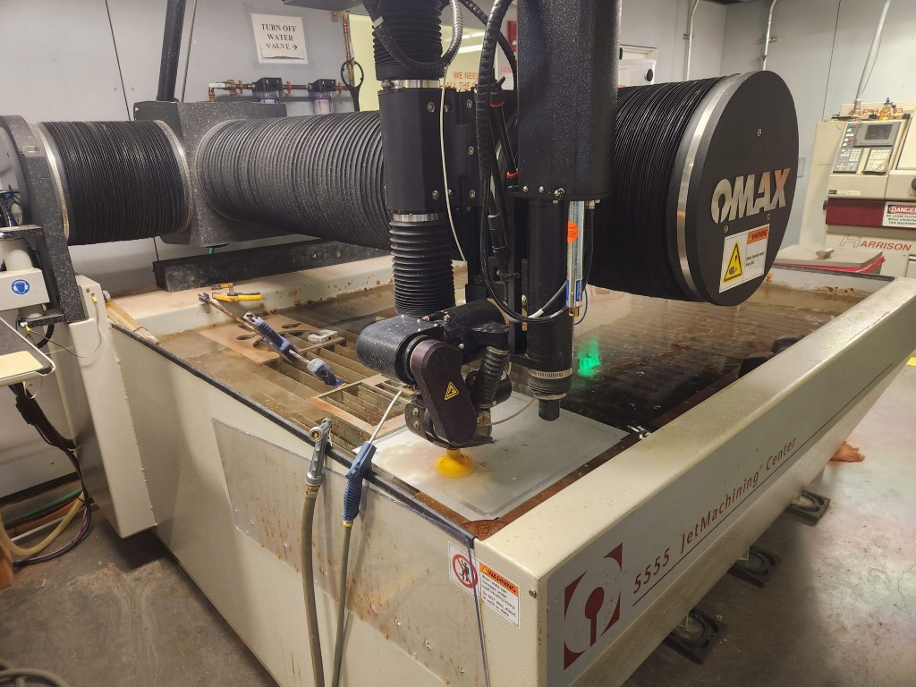
Waterjetting the part at the Media Lab
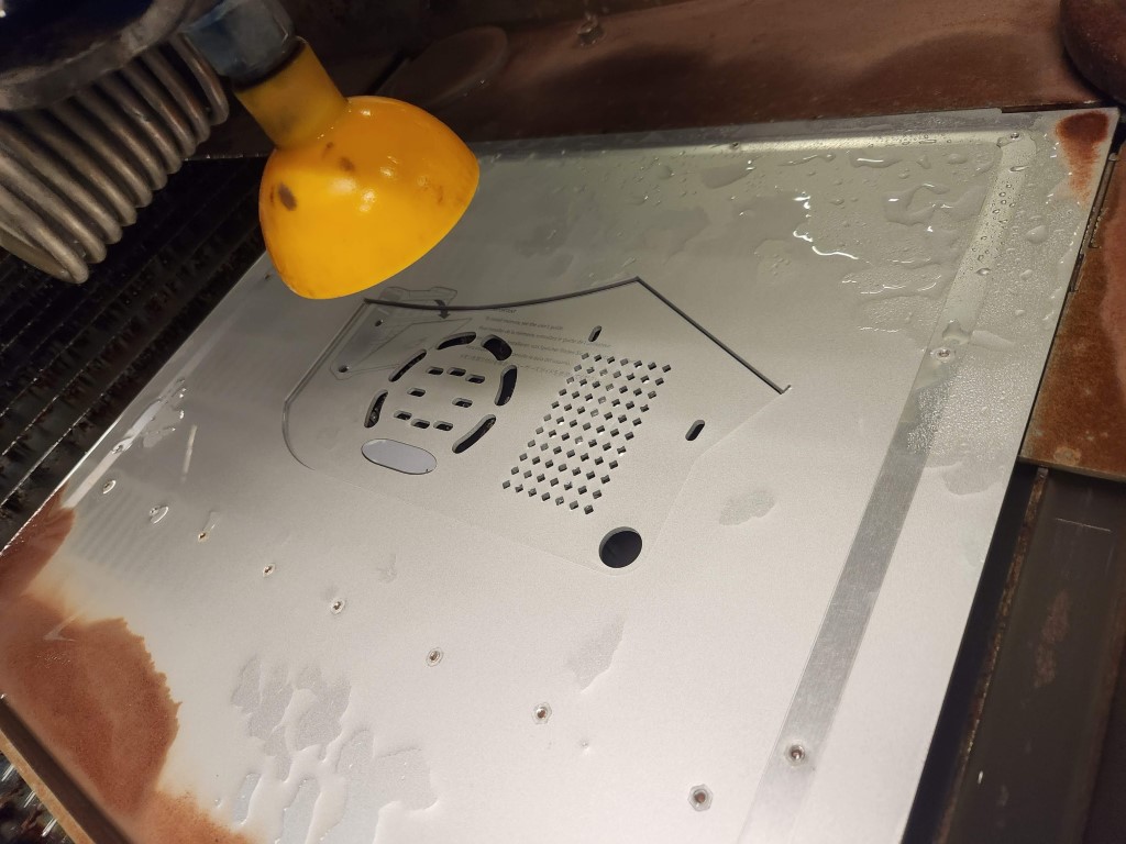
Close-up of waterjet
Assembling the bike
The parts bolted onto the bike… surprisingly smoothly! One hiccup was the fact that the motor poked out too far in CAD, and the chain from the motor to the rear sprocket was crooked. In other words, my CAD was incorrect about the placement of the motor. This was fixed surprisingly easily by removing the spacer I put between the motor and backplate. Voila, problem solved.
Electronics
I’m using 10S of lithium-polymer batteries from two Turnigy batteries connected in series. For the motor controller, I’m using an off-the-shelf Flipsky VESC 6 controller. For the motor itself, I’m using an outrunner motor designed for… agricultural quadcopters! It’s a T-Motor P80 II KV100 motor, designed to turn large propellers slowly with lots of torque on big drones. It’ll still need a reduction to drive the rear wheel though.
The electronics also hooked up without a problem. After wiring everything up, it was super satisfying to see the motor spin!
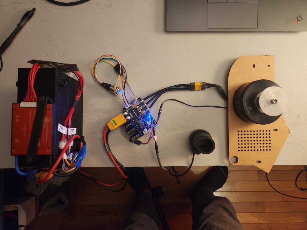
First integration of the powertrain!
Riding the bike
Holy cow. When this bike works… it’s fast! I’ve recorded 25.3 mph top speed, with my pedaling speed being the limiting factor. It gives a nice boost when you’re starting to pedal, and helps you accelerate to a comfortable speed when not being pushed to the limits. It’s definitely breathed some life into this derpy old bike I bought off Craigslist.
My record is riding four miles continuously without problems. Shortly after that, the battery management system (BMS) decided to take a nap and shut off my bike, even though there was still energy in the batteries. I have to replace the BMS with something more trustworthy, I suppose. Also, the tensioner is still a work in progress. When riding the bike, the tensioner occasionally falls off the chain, causing the chain to lose tension and derail. On one occasion the spring flew out of the tensioner assembly while riding, so I’ll try hot-gluing the spring in place for future versions. This moving part will take some more trial and error to get right.
It’s been a great project, and I’ve learned a lot about CAD, bikes, and designing parts. Hope to keep riding this bike into the future!