Final Project: Pauto
With everyone leaving campus for the holidays, there's a major group that is left behind and forgotten, forced to fend for themselves for weeks, stuck in dorm rooms. That right: it's the MIT plant population. Personally, I have two plants that I've been taking care of for the past year in my dorm room, and I've been worried about them for the past few weeks. I need a way to to make sure they're getting enough water and nutrients, and checkup on them while I'm away.
That's where Pauto comes in: a plant sustenance and sensing system that allows you to monitor your plants and make sure they're getting the care they need. It consists of three main subsystems: the physical potting system, the plant sensors/motors, and the backend server. The potting system is a self-watering pot that uses a water pump to water the plant when it needs it. The plant sensors are a soil moisture, temperature, and humidity sensor that are placed in/near the plant to monitor its health. The web app is a web interface that allows you to monitor your plants and control the potting system directly.
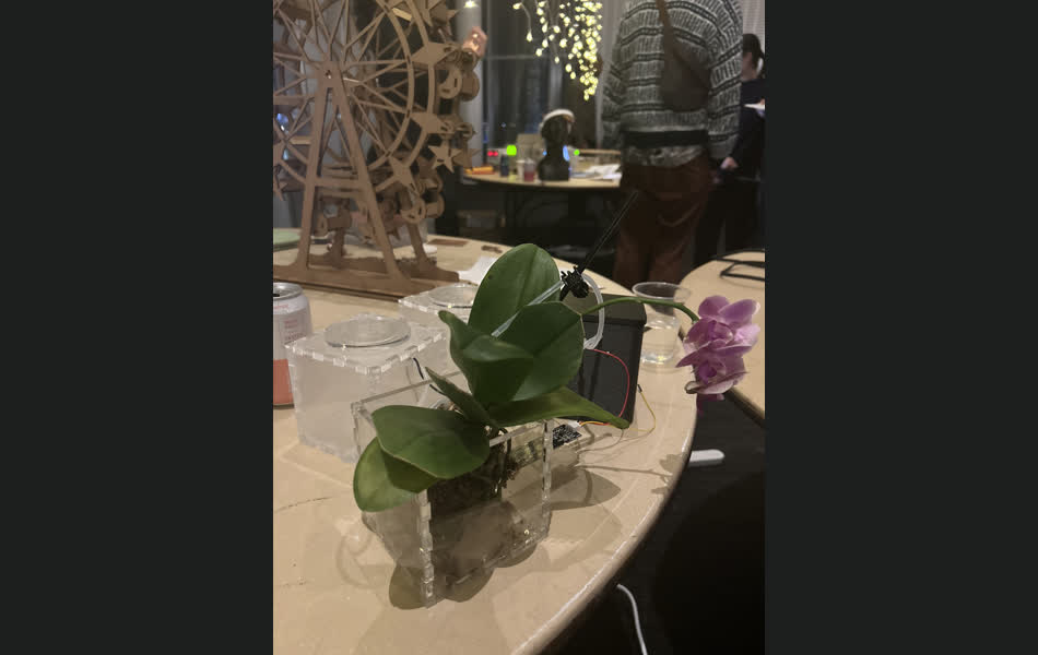
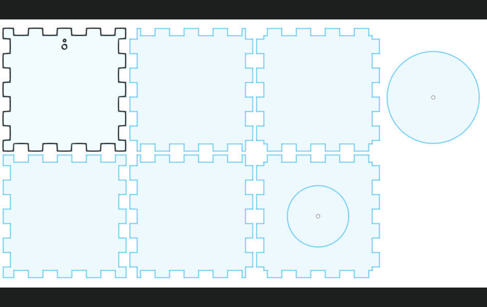
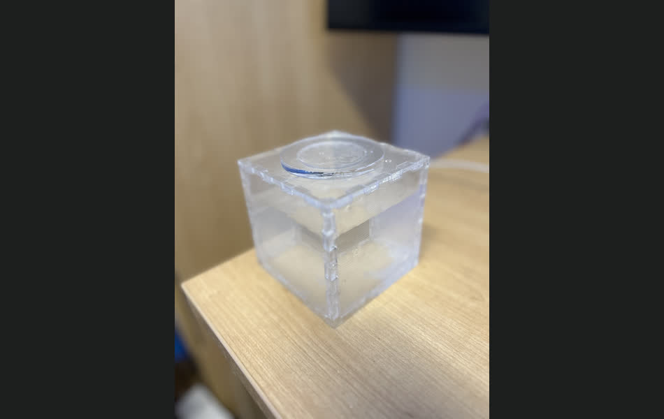
First, let's discuss the potting system. I knew that I wanted the pots to be aesthetically pleasing (and not just standard clay/plastic pots), so I decided to make them myself out of acrylic, and design them in a way that made them look clean and modern (unlike the rest of my room). After much iteration, making mistakes with the tolerances of the tubing and sensor units, I finally got a design that I was happy with. The potting system consists of three main components: the water reservoir, the nutrient reservoir, and the plant pot. Ther reservoirs are connected to the plant pot via plastic tubing, which goes directly into the soil; meanwhile the reservoirs must have tubing within them that goes to the pumps that pump the water/nutrients into the plant pot.
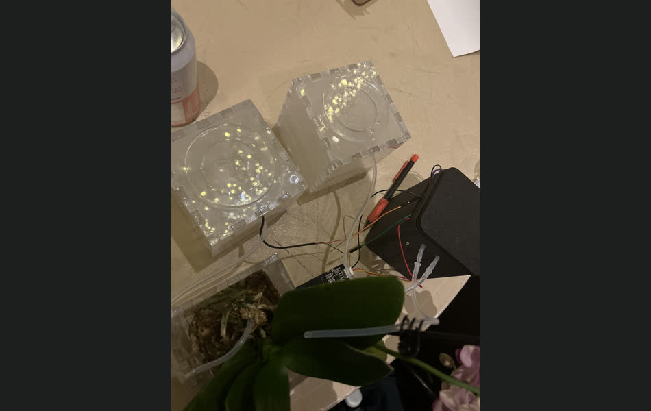
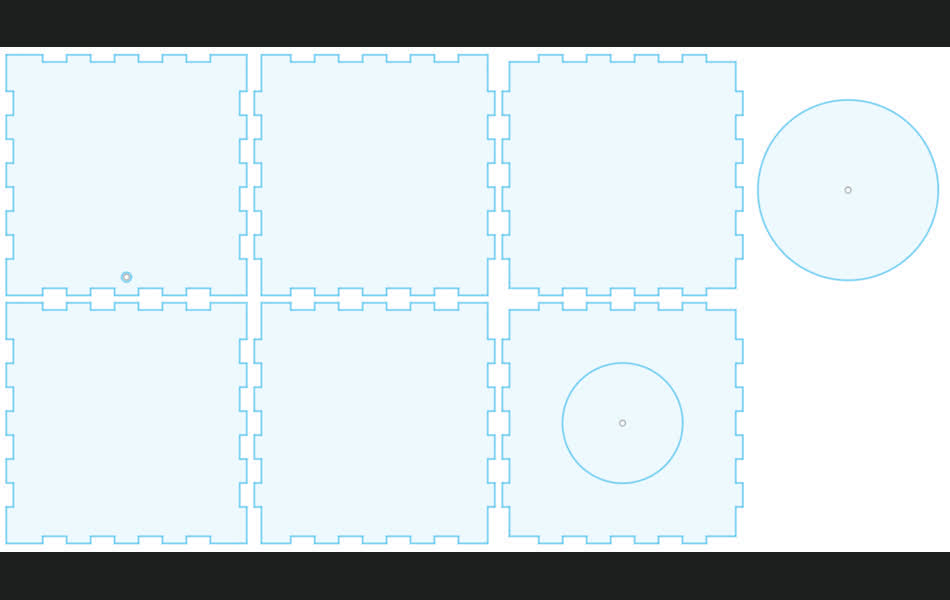
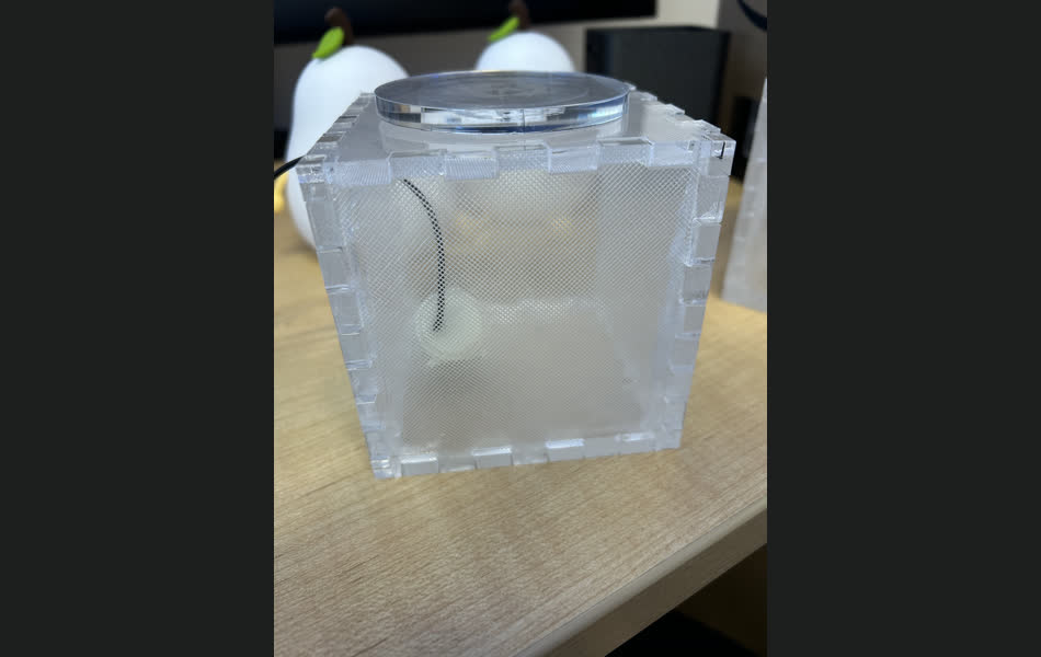
The general structure of the acrylic potting system is shared across all three components. They were constructed as individual slabs of acrylic, with finger joints to connect them together, cut with a laser cutter. The two contrainers holding liquids were also rastered to give them a nice sparkly/cloudy finish (depending on lighting conditions). The finger joints were then glued together with super glue, and the edges were sealed with hot glue. Originally, epoxy was tried to seal the edges, but it was too messy and difficult to work with, so hot glue was used instead. The boxes' water seal was tested, and if it was not watertight, it was resealed with hot glue. The final product was a nice, clean, and modern acrylic potting system, with pretty and easy to remove lids for easy access to the reservoirs.
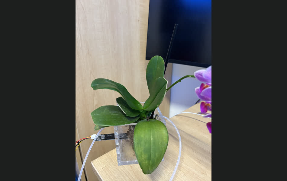
As is visible, the pot goes inside the waterproof acrylic enclosure, which has two holes for the tubing of the water and nutrient reservoirs. There is also a thin slit for the soil sensor array to go through, which is used to monitor the soil moisture.
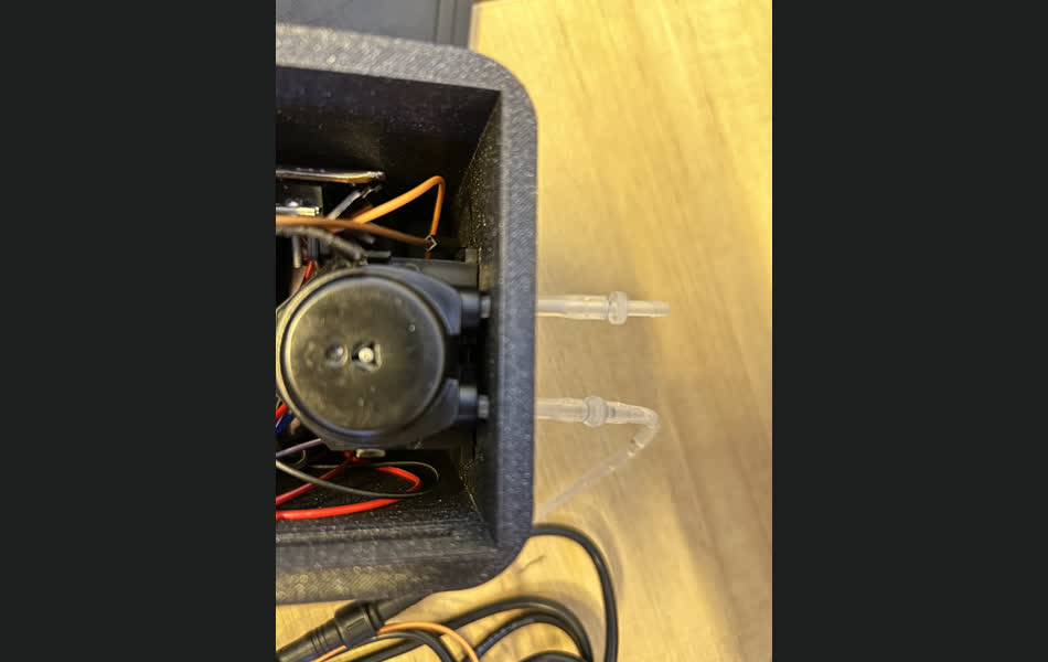
The structure of the liquid reservoirs is similar to the potting system, but with a few key differences. The water reservoir has a hole for the tubing to pump the water out, but also a hole for the water pump wiring, since it's submerged in water:
The nutrient reservoir has only one hole for the tubing to pump the nutrients, since that system is powered peristaltically. The reason the water reservoir is powered by a submerged motor and the nutrient reservoir is powered by a peristaltic pump is nutrient mix may leave some residue on the motor, which could cause it to be damaged.
Originally, I had been thinking about using a hydroponic system for the plant potting, but I decided against it because it would be too difficult to implement, and would also not generalize well to plants (like mine) that drown in that much water.
Now, we can discuss the second main subsystem, the electrical system, and how it interfaces with the other web and physical components. The sensor array is a soil moisture sensor that is placed in the plant pot itself, and a joint temperature and humidity sensor that is placed in the main electronics enclosure.
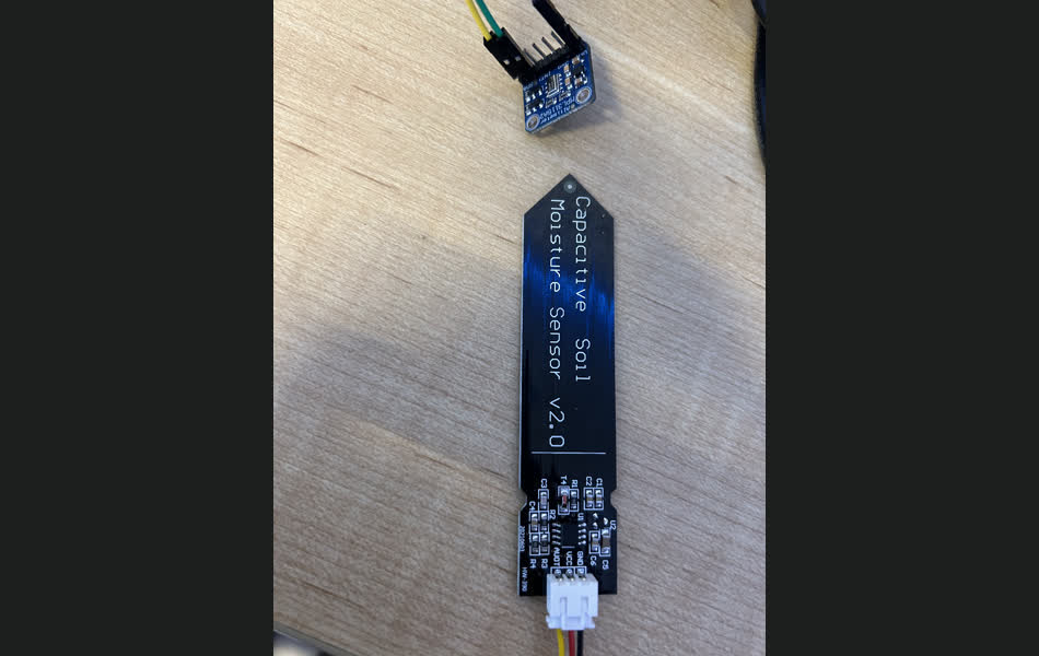
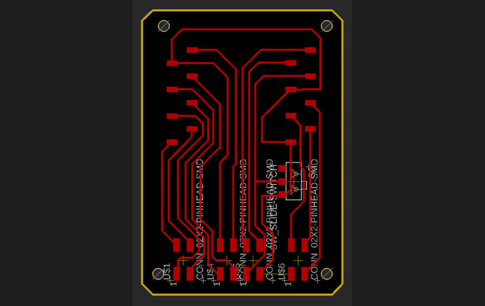
The moisture sensor is a capacitive sensor that is placed in the soil, and is connected to an analog input on the ESP32. The temperature and humidity sensor transmits data over I2C, and is connected to the ESP32 via I2C. During development there were many issues faced while interfacing these sensors with the ESP32 CAM, since there are limited pins exposed, and many are rendered unusable due to the WiFi module. As described in my input week writeup, the ADC pins that were used for the moisture sensor were not available while WiFi was active, so the code cycles between WiFi and ADC readings to get the most accurate readings possible and still push them to the server. There were also issues of some pins being set to default HIGH, meaning that the range of options of pins was narrowed down to 4 or 14; furthermore, 4 is connected to the LED, which can get quite annoying and drains a lot of power if left on, so 14 was chosen for the analog moisture sensor. As for the I2C pins, they could be chosen as any other available set of pins. The ESP32 PCB is shown below:
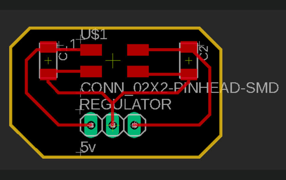
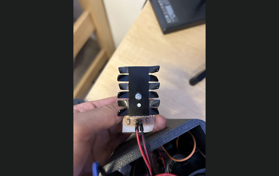
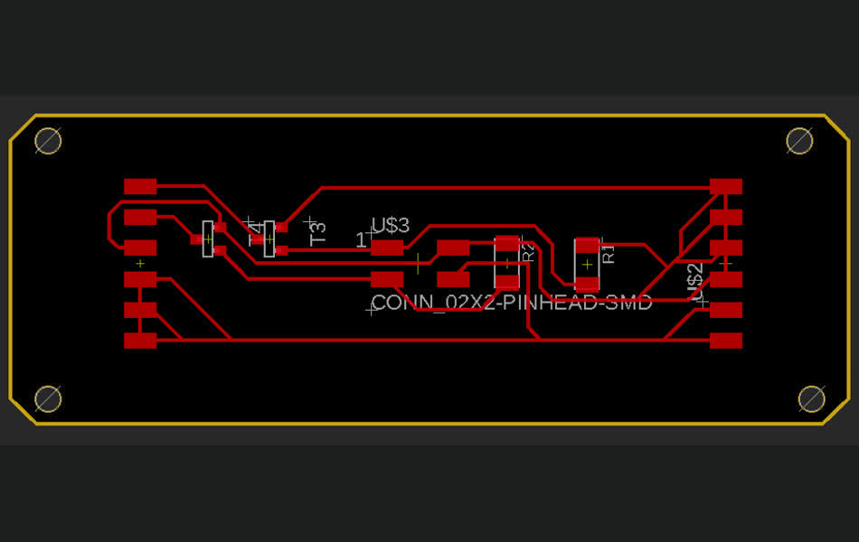
Since one of the main goals of this project was to make it as easy as possible to set up for other users, I decided to make it able to plug into the wall, so that it could be used anywhere, independently. The power supply outputs 12V, which then needed to be converted to 5V for the sensor array through a voltage regulator, the PCB design of which is shown below. It got hot enough during testing that a large heatsink was needed to keep it cool, and the PCB was designed to be able to be screwed into the heatsink.
Now, with a working power supply, input sensor array, we can discuss the motor control system, which is a MOSFET. The MOSFET is controlled by the ESP32, and is used to control the water pumps; increasing the voltage on the gate of the MOSFET increases the current through the drain-source, which is used to control the speed of the water pump. The MOSFET PCB is shown below:
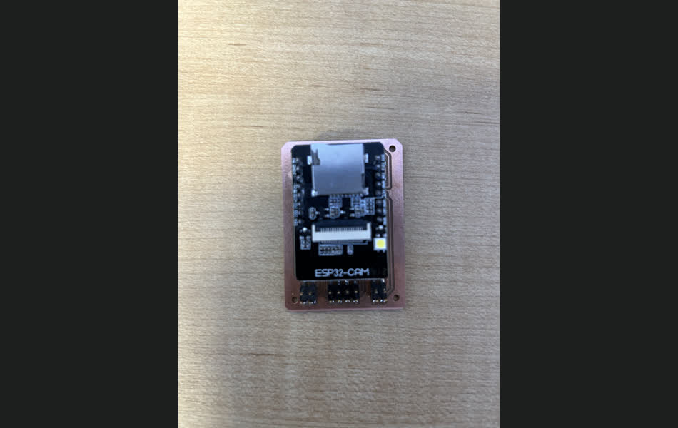
For some current in-development improvements, a nutrient sensor is being added to the sensor array, which will be used to monitor the soil for nitrogen, phosphorus, and potassium levels. This will be used to determine when to add nutrients to the plant, and how much to add. The sensor is a 3-in-1 sensor that will be connected to the ESP32 via I2C; however, it is a bit tricky to set up since it has it needs to be spoken to to return the data, and it also needs to be calibrated. Additionally, a camera is almost functional on the ESP32 CAM, which will be used to take pictures of the plant and send them to the server/user; the main issue right now is that there are further pins that can not be used while the camera is active, so some internal re-wiring (removal of wiring to useless SD card) might be needed to make it work.
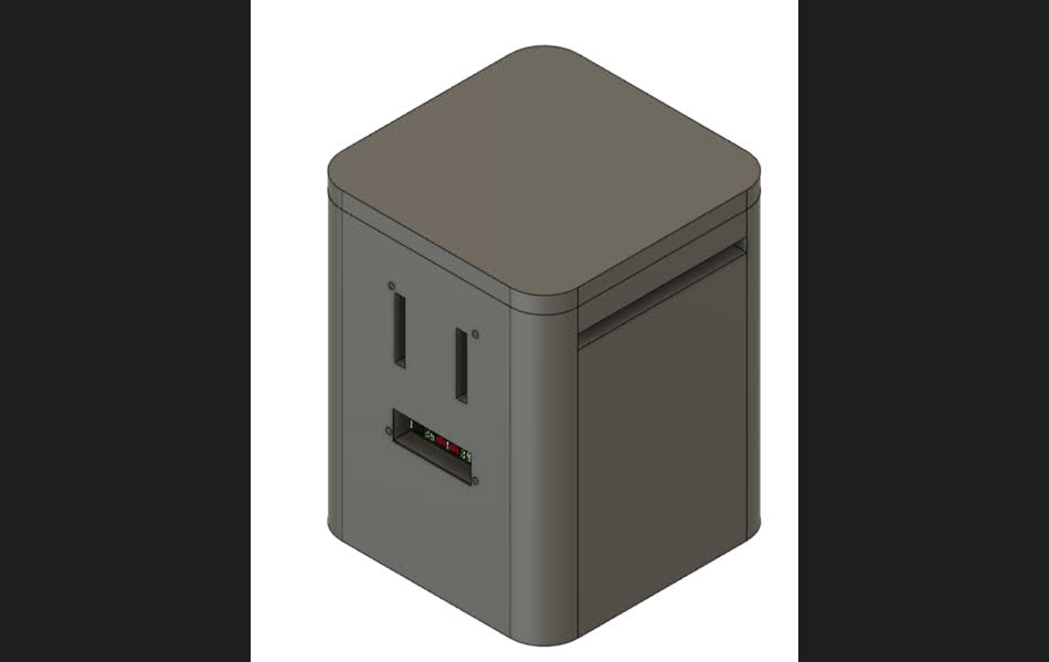
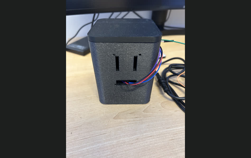
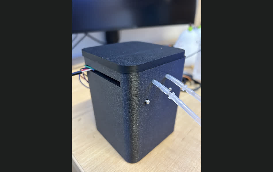
Finally, to make this system compact and easy to use, I designed a 3D printed enclosure all of the electronics to fit into. Nicely, the ESP32, with the intended camera attachment, fits over the case, but inserts into the PCB on the back, keeping only the necessary parts exposed. Additionally, there are screws holding together the internal components to maximize the longetivity of the device. The PCB to Fusion functionality worked perfectly here to set up the internal structure of the 3D model. It fully contains the peristaltic pump, only exposing the tubing. The enclosure is shown below (and it's shaped like a smiley face :)
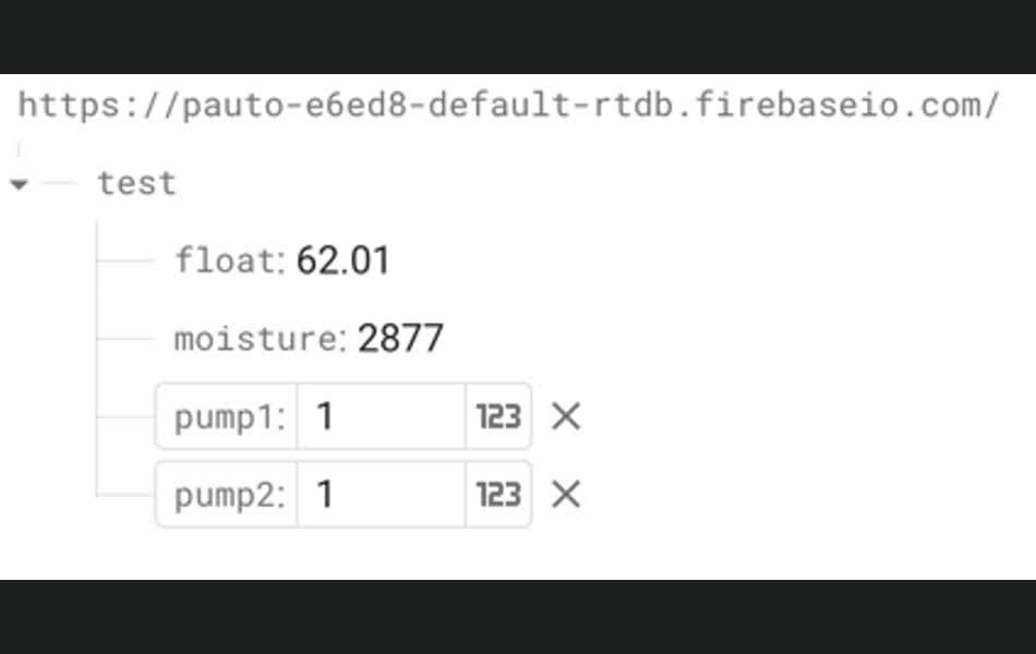
Finally, we can go into the backend server of the system. The server is a Flask server that is hosted on a free GCP instance, and is used to send commands and store data sent from the ESP32 to the Firebase server. The server has a few key functions, which are to intermittently send a "watering" command to the ESP32, which is used to control the water pump, and to send a "nutrient" command to the ESP32. If the moisture sensor detects that the soil is dry, the server will send a "watering" command to the ESP32, which will then turn on the water pump for a set amount of time. Some improvements to this system include a more robust UI (however, I don't intend to be watering the system manually, so the backend is all that is necessary for me).
And that's all! I had a total blast working on this project, and I learned a lot about the entire fabrication process! Thanks so much to Anthony for being a great TA, and for all the help he gave me throughout the semester and ESPECIALLY over the last week of final project time. I hope you enjoyed reading about my project as much as I enjoyed making it! I'm excited to say that the device has been working for the last few days keeping my plant alive, and I'm excited (and a bit terrified) to see how it does over the next few weeks! Hopefully, I will be able to return to some thriving plant life in the near future!