**[Raiphy Jerez's site](../index.md.html)**
Personal website for [MIT MAS.863/4.140/6.902(0)](https://fab.cba.mit.edu/classes/863.22/)
# **Oliya: Electric ATV**
Joint effort with [Ahmad Taka](../../Ahmad/page/final-project-details.html)


Task List
- [x] Cast resin suspension sleeves
- [x] Waterjet motor mount
- [x] Weld
- [x] Headlights, Taillights, Turning signals
- [x] Battery
- [x] ∫
# Resin suspension sleeves
Week 8: design a mold around the stock and tooling that you'll be using, mill it, and use it to cast parts
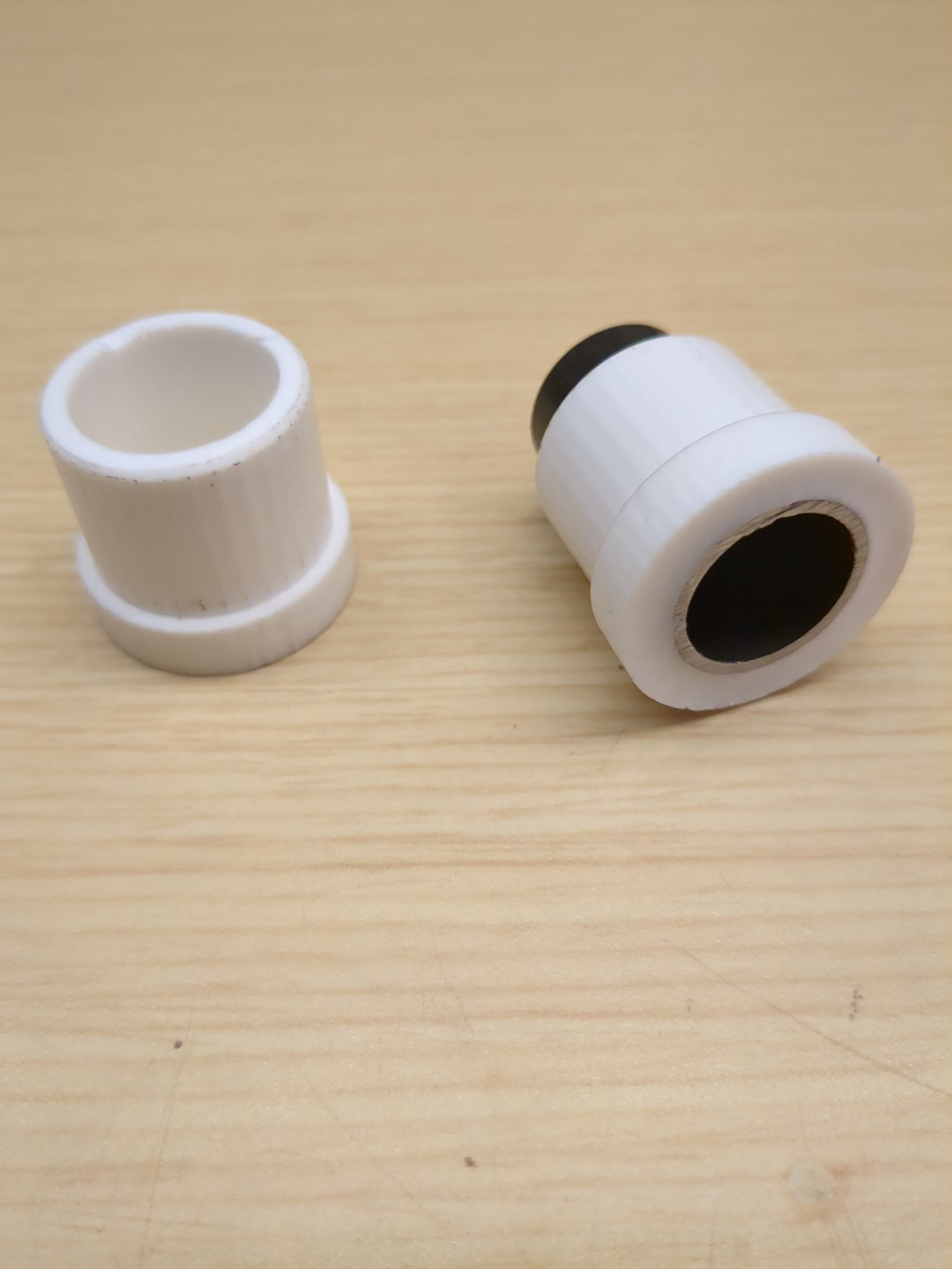
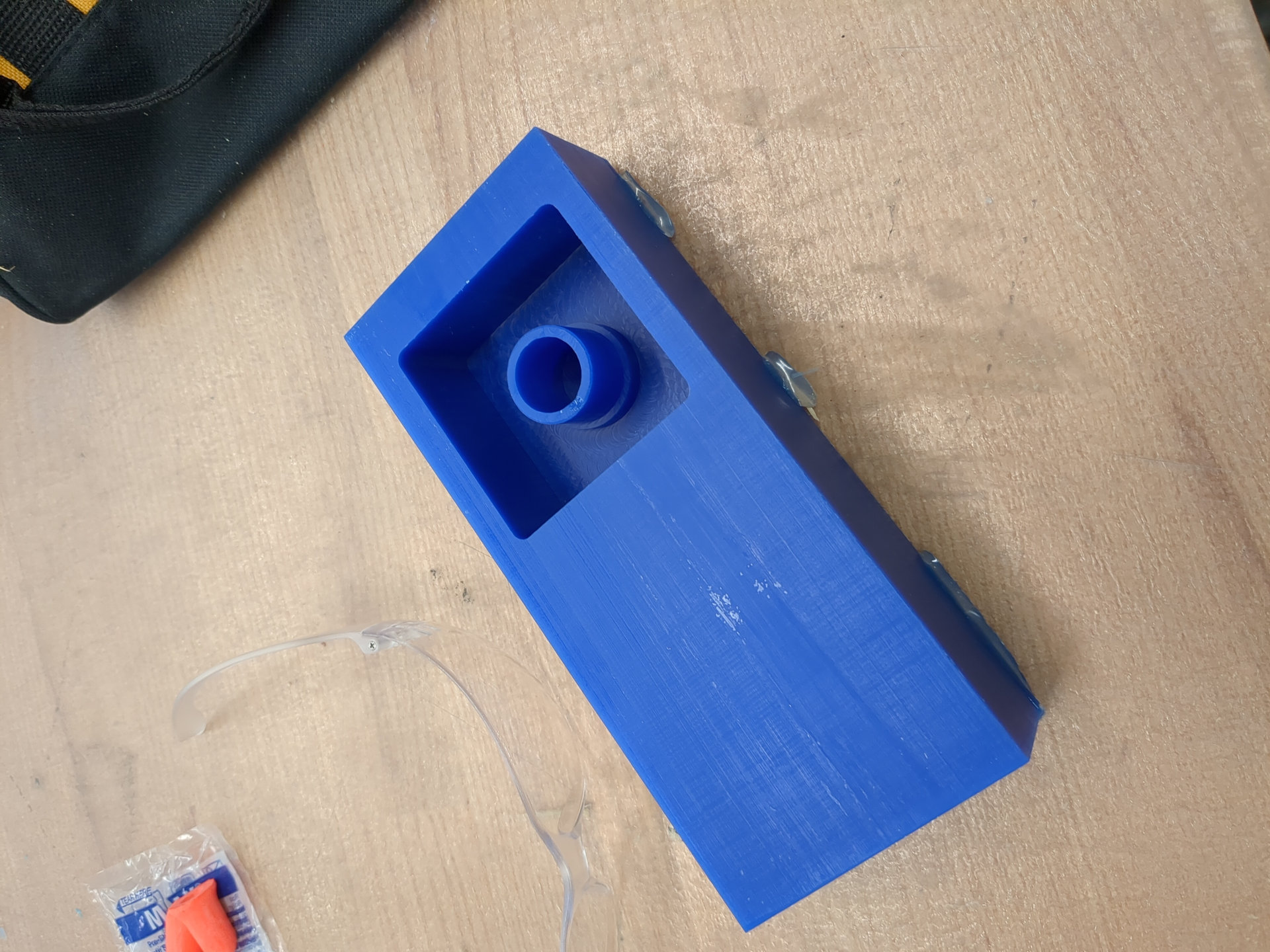
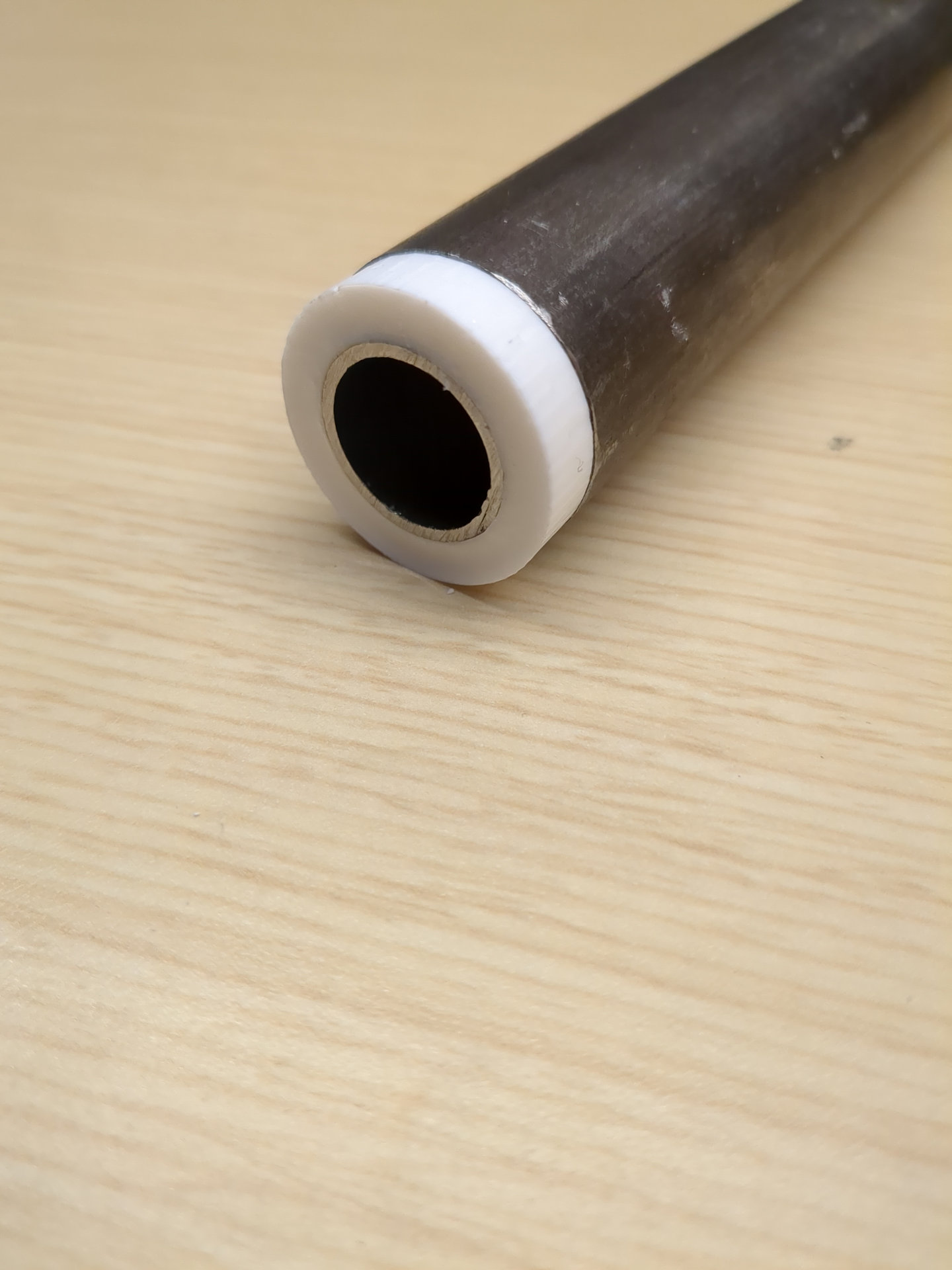
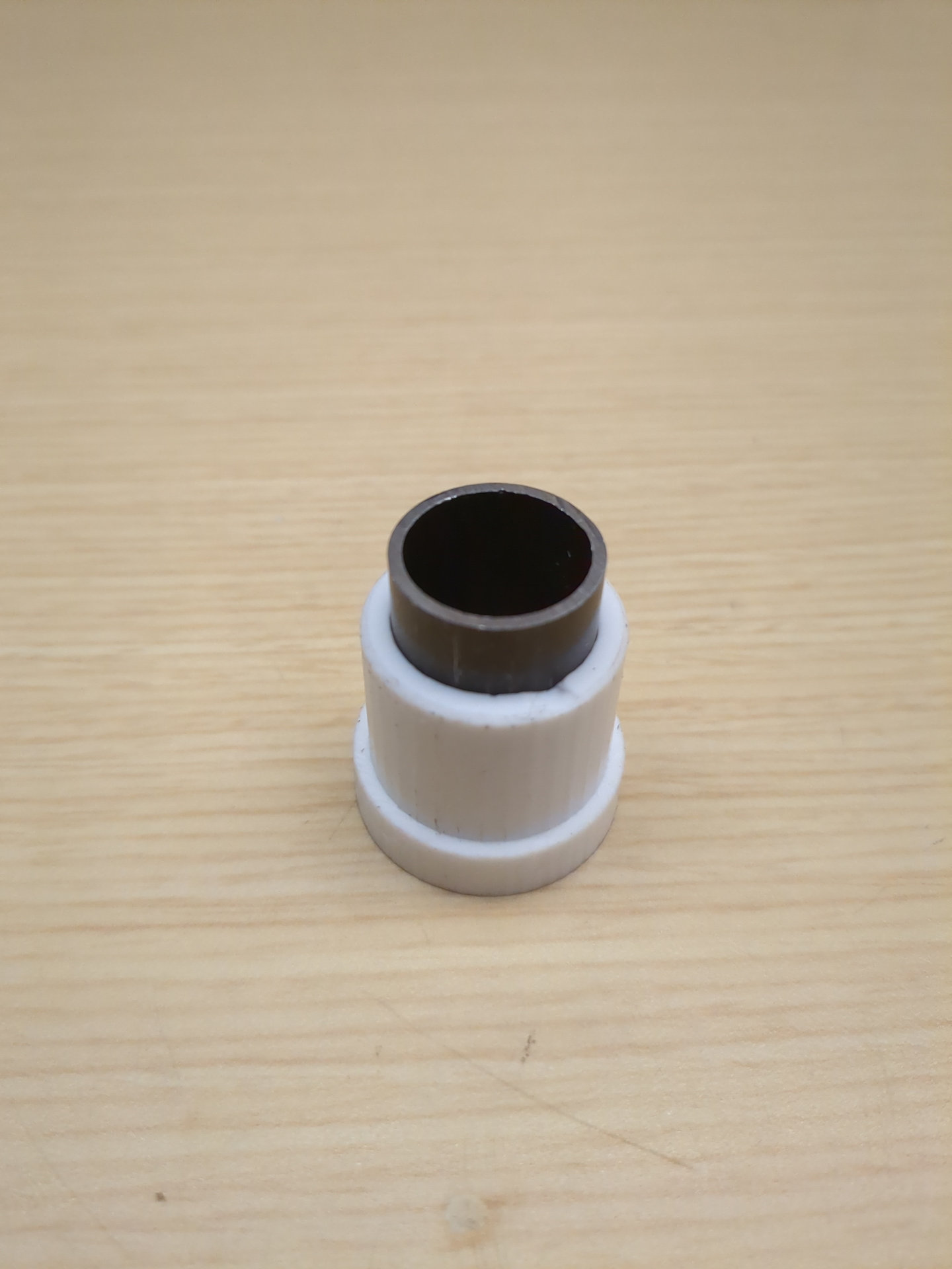
I wanted to make a part that would center a 3/4" pipe within a 1 1/8" pipe. Although it would be faster to 3d print one or 2 of these parts, I can make multiple silicone molds and make multiple at once in the time it would take a 3d printer to make one.
## CAD/CAM
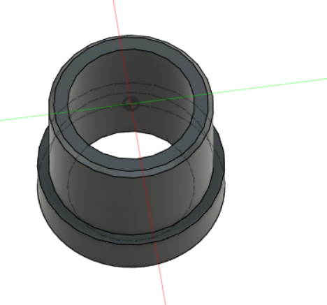
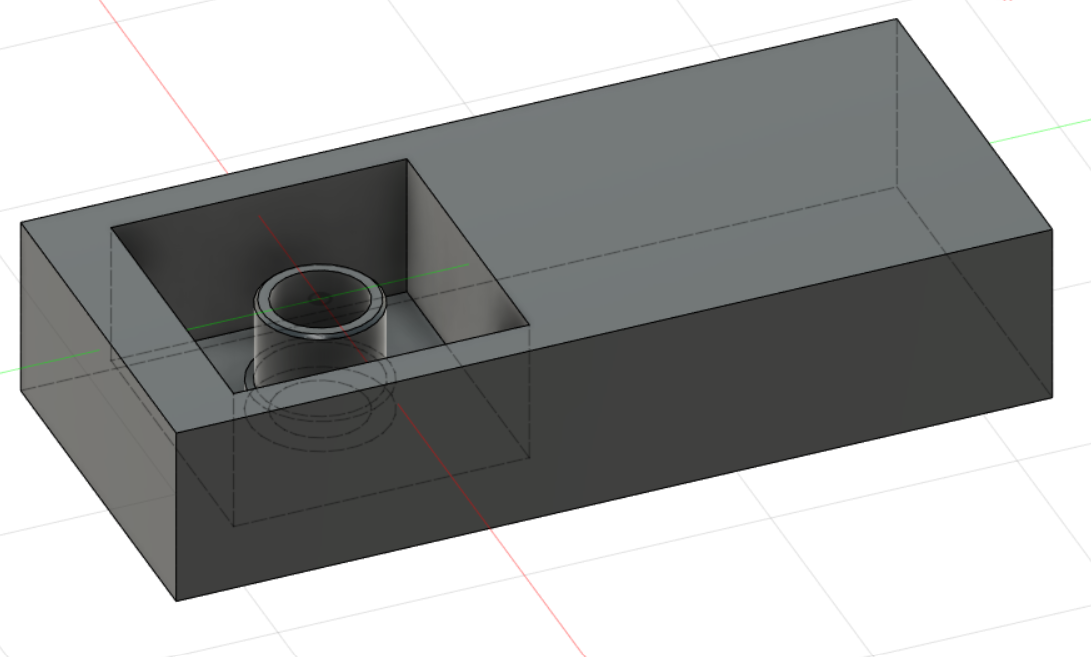
The design was just a parametric sketch and a revolve around the Y axis. I then modeled the stock around where I wanted the mill to machine the part from. Because my part was so small, I put the job one one half of the wax brick stock so the other half could be used for another job.
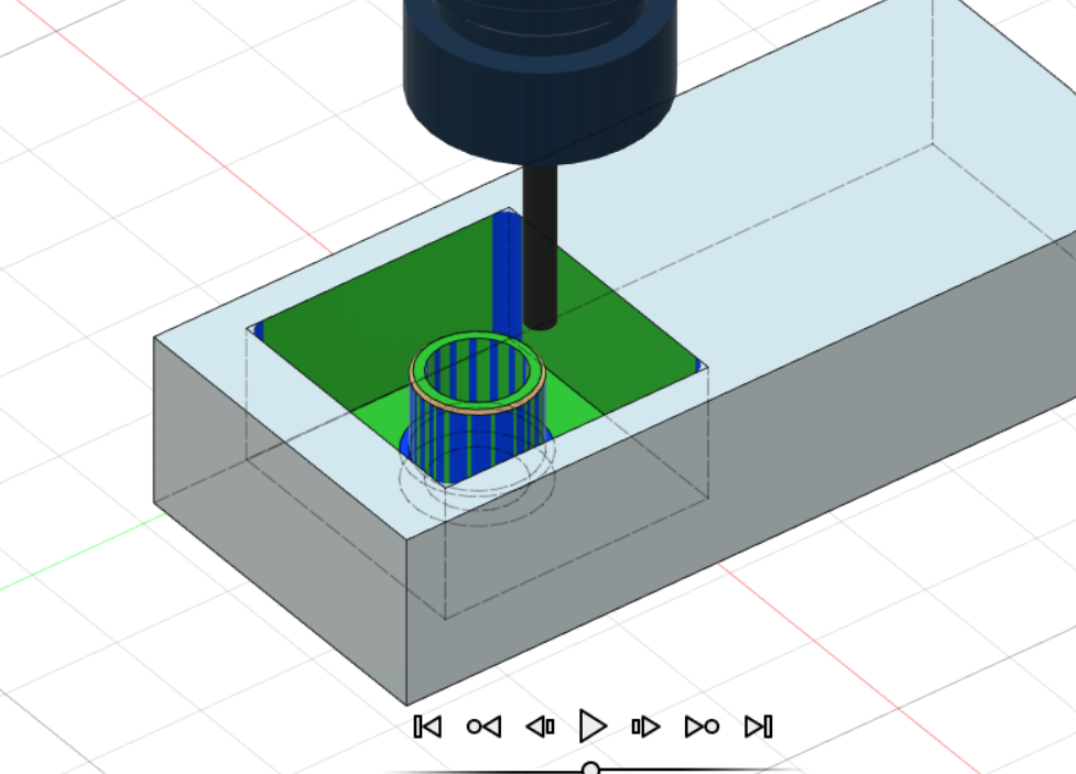
In CAM, I used 2 operations to clear away the wax around the part and for the mold. I used a final flow operation to create the chamfered edge around the exterior of my part. I set the tool size to 1/4 inch and a spindle speed of 18000rpm. The feedrate was set to 100 IPM but it was later fiddled with at the machine.
## Milling
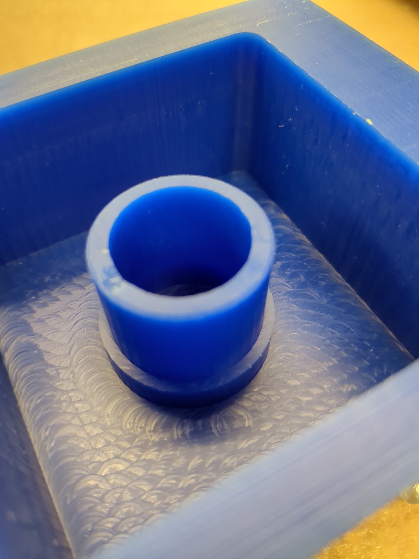
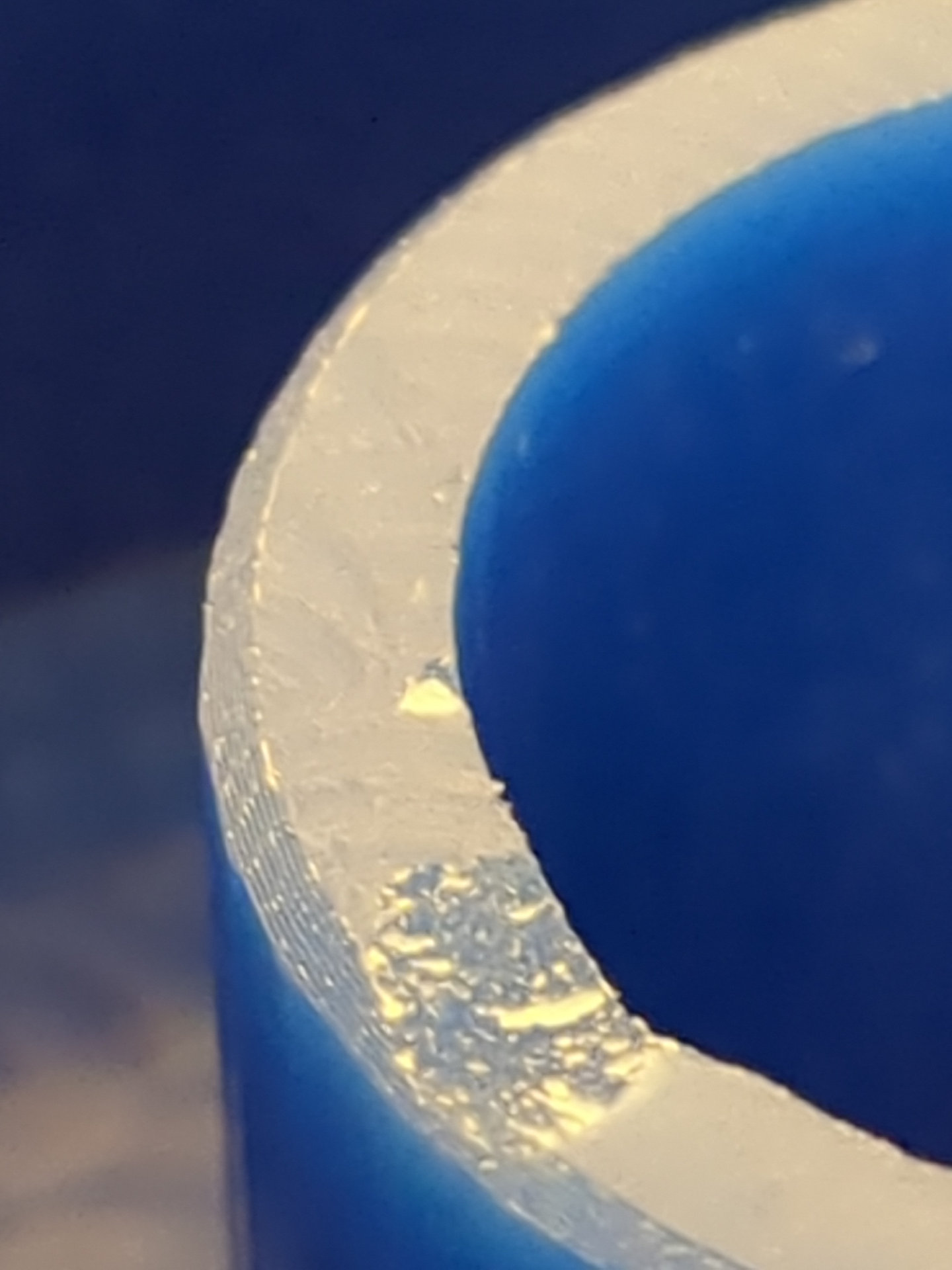
Milling was uneventfull. The whole job took around 10 minutes. The top edge of my part has a small chip in it. Other than that it turned out just like the CAM Sim.
## Creating the Mold
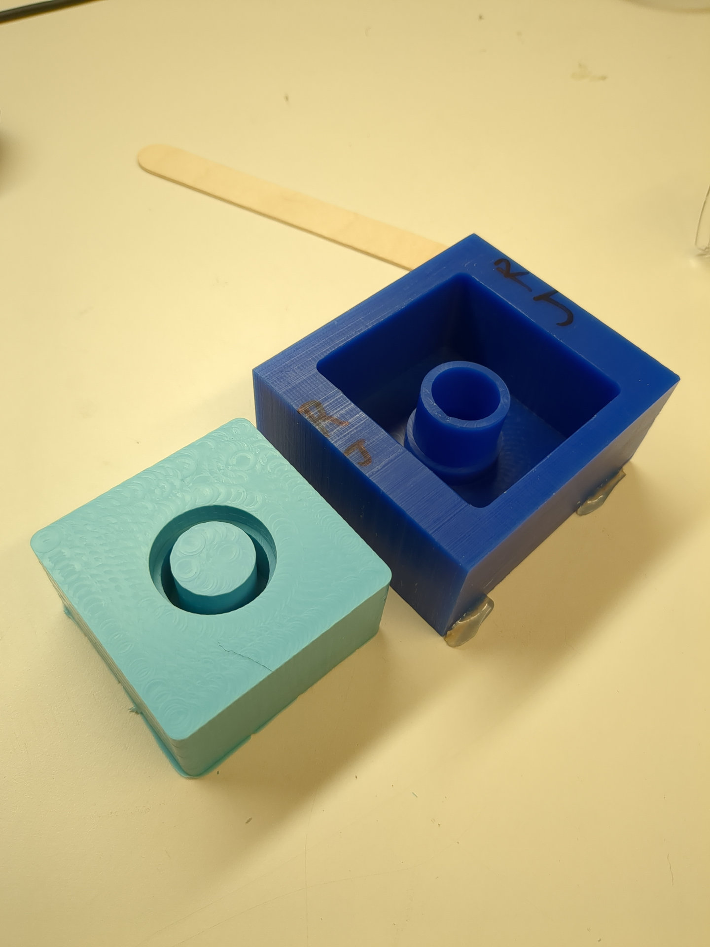
To create the mold, I mixed up equal parts of Oomoo part A and B by volume. After letting it cure for a day I extracted the silicone mold from the wax mold.
## Casting the Part
I casted the sleeve in smooth-on smooth-cast 305. I extracted it from the silicone mold after waiting 30 minutes and it was still soft. I took this chance to press it into the steel tubes to make sure they fit.
## Final Product

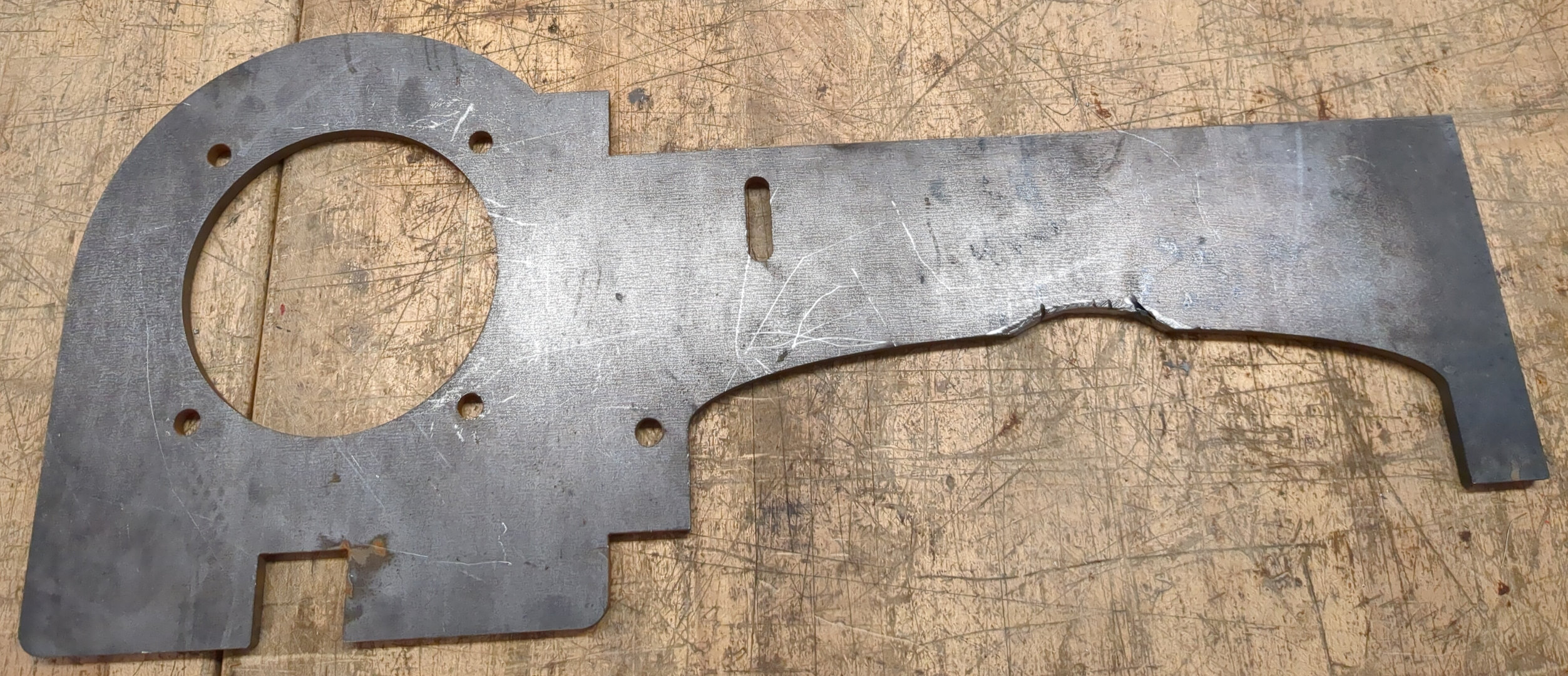
# Waterjet machining
I decided to make the motor mounting plate for the Electric ATV using the Waterjet machine at CSAIL. I was trained to use it a couple months ago by Ron.
I designed the plate to be able to slide into the rear suspension assembly. Because I didn't want to waste the steel plate we had, I cut out the piece on some wood first.
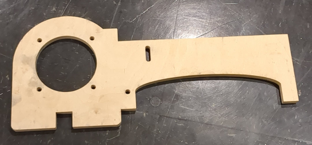
I then used the wood piece to test fit it inside the rear suspension. It fit perfectly. Time to waterjet the steel plate.
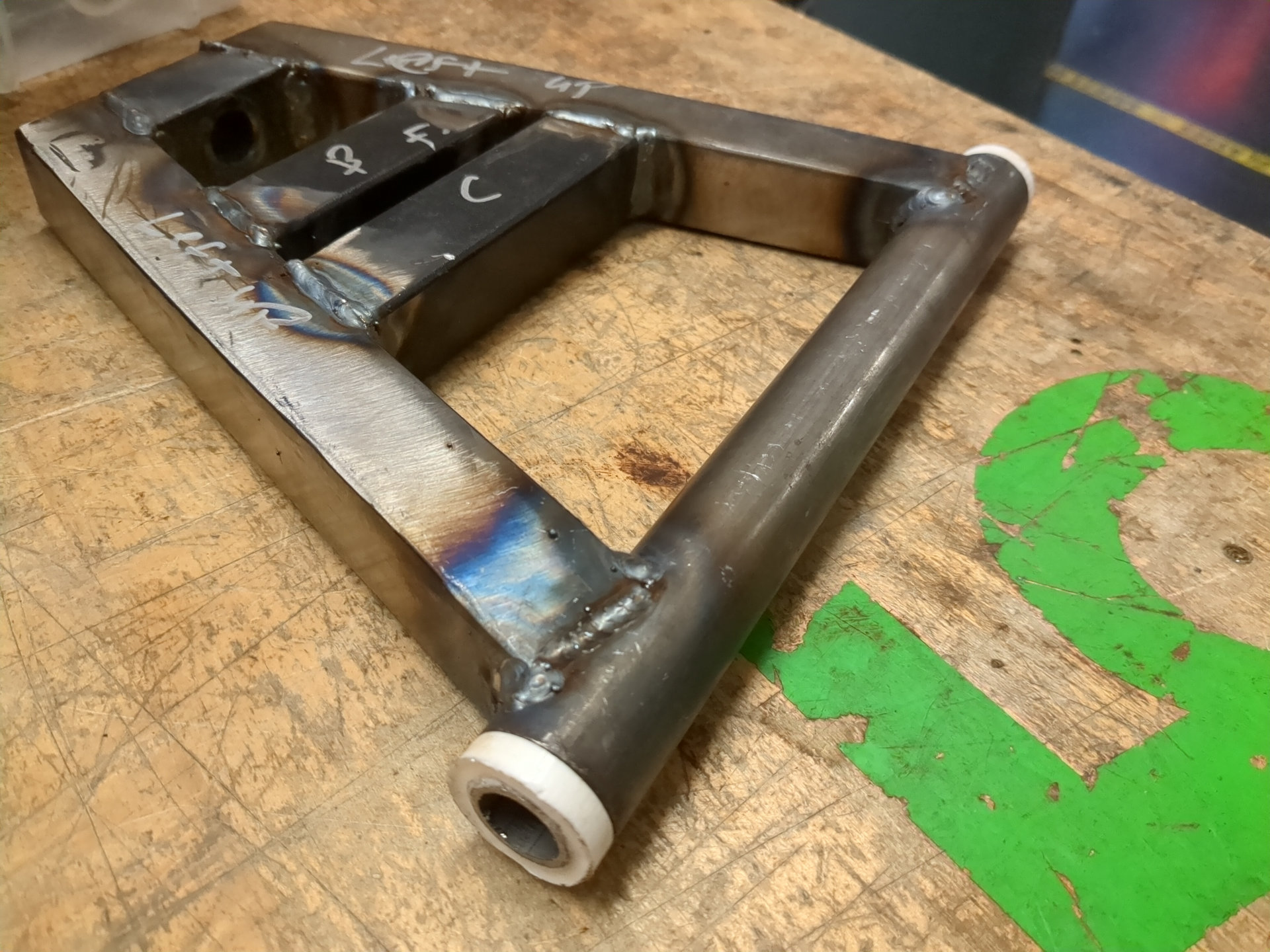
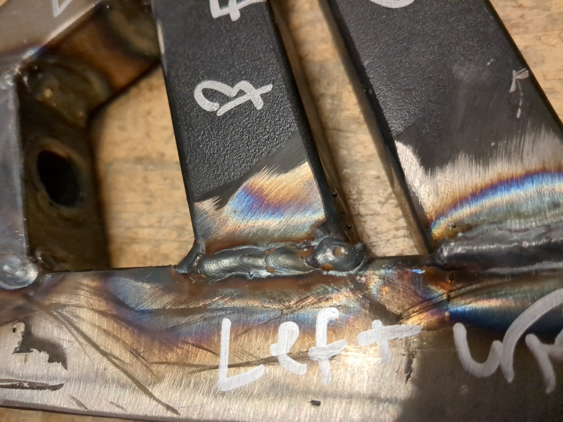
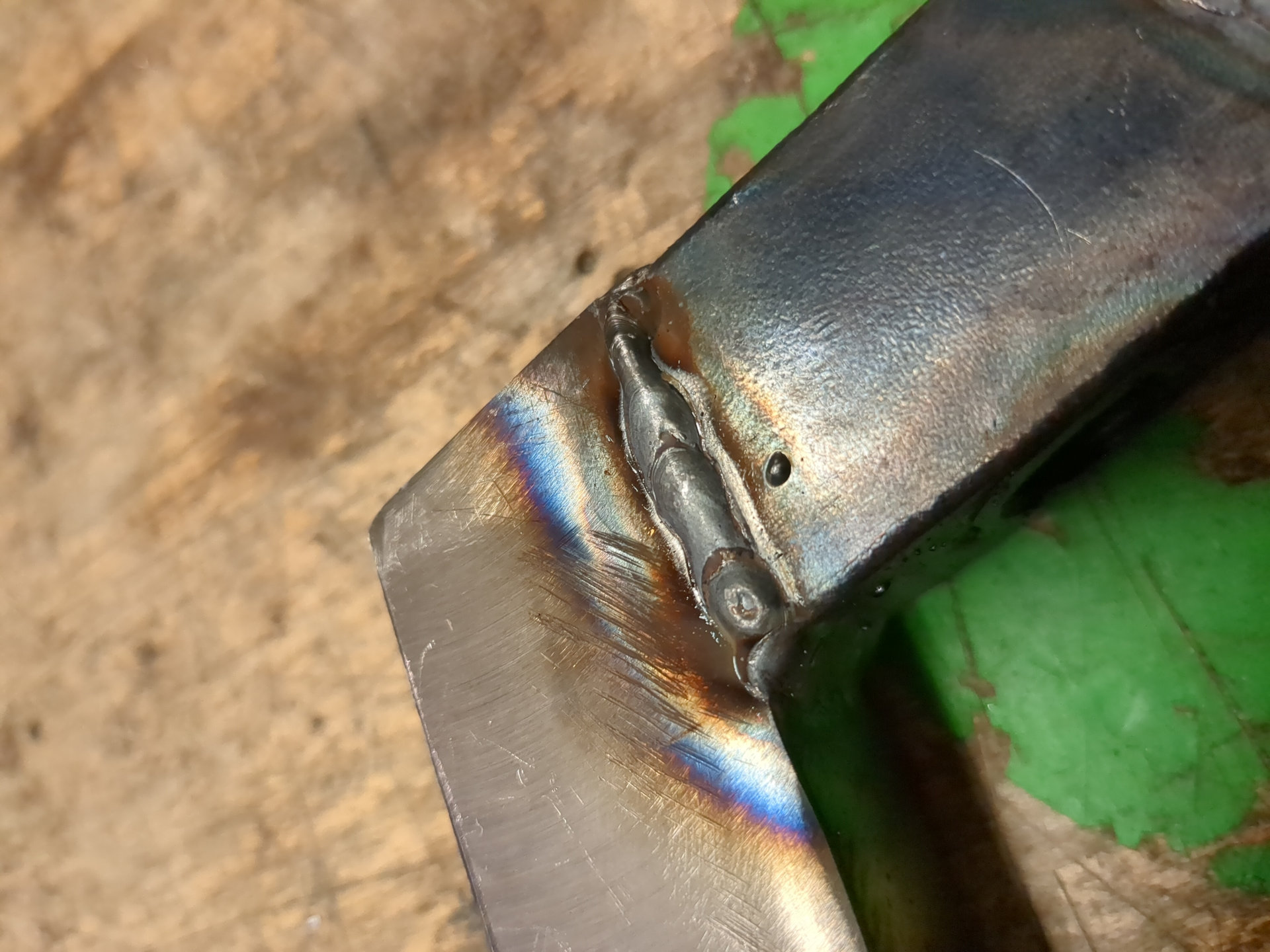
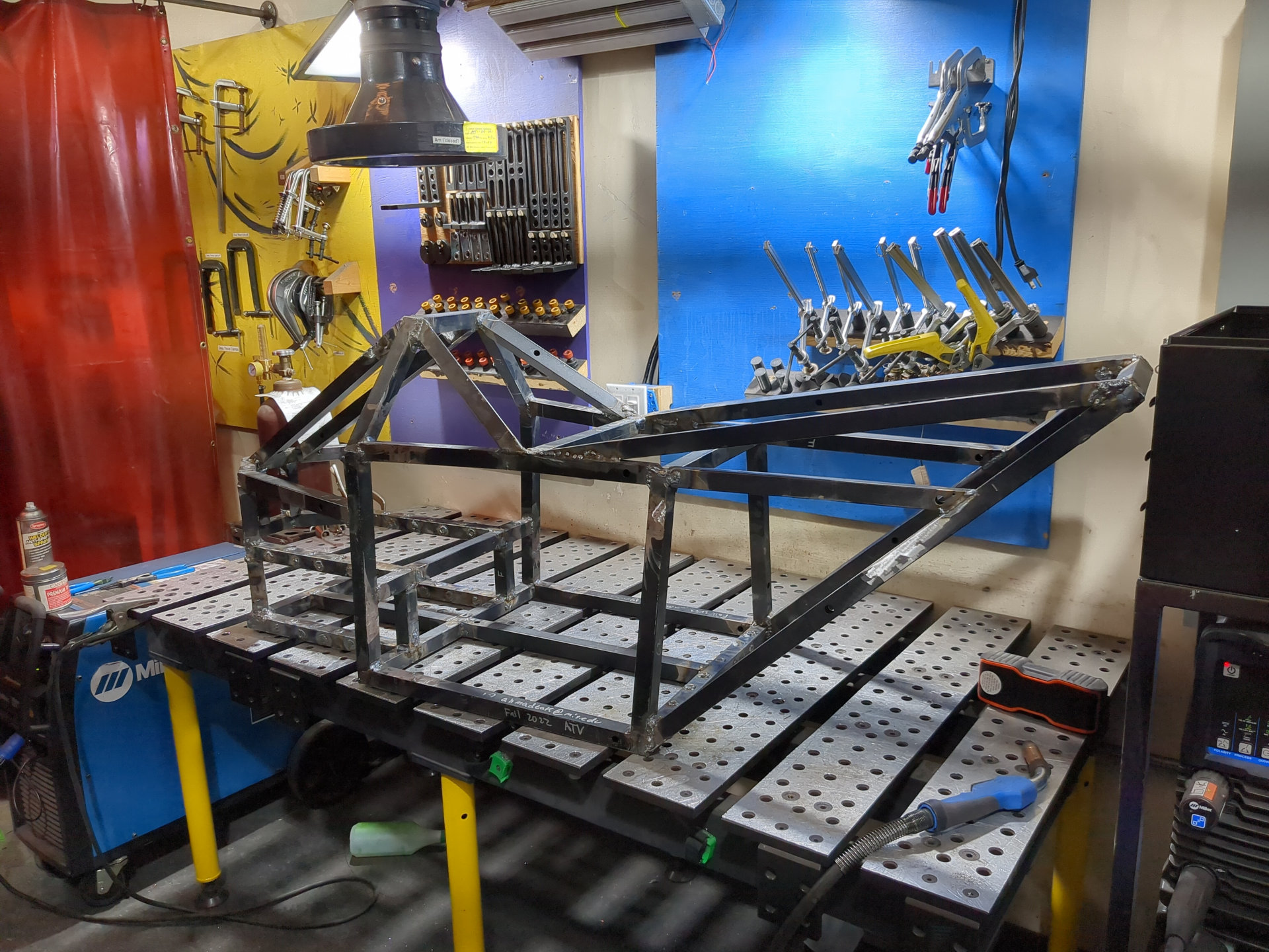
# Welding
I welded the arms for the front suspension. I am using a MIG welder to make the welds for the ATV. As you can see from the pictures, I need a lot more practice to get more consistency in my joints.
# Headlights, Taillights, and Turning signals
## Headlights
I elected to build the headlights for the ATV. For the headlights I chose to use a premade LED bulb from Home Depot. I did this because I want the bulb to be waterproof and easily replaceable.
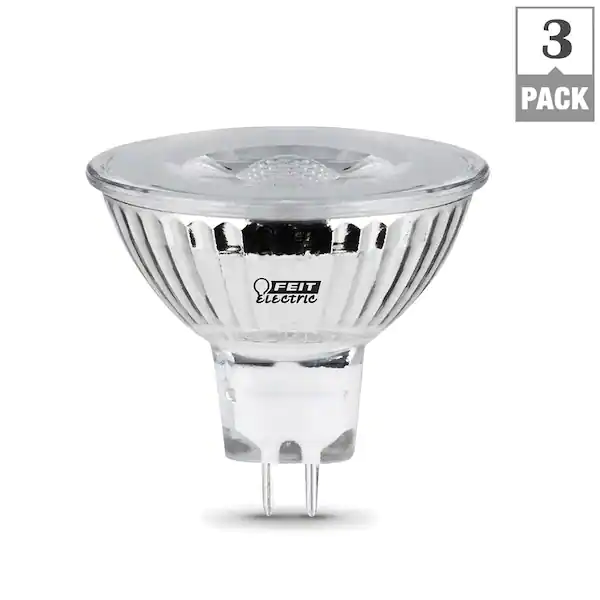
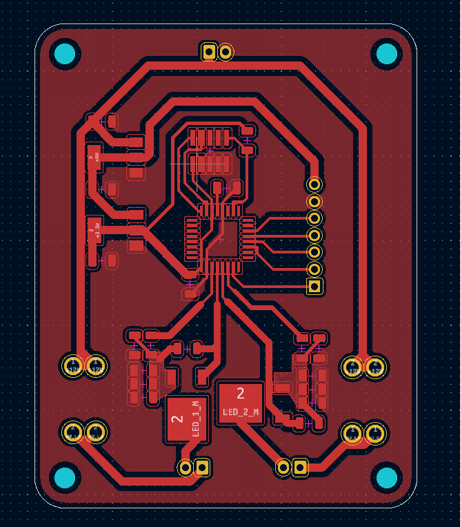
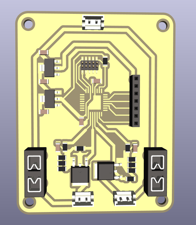
These bulbs are nice because they are designed to run off 12V AC and are dimmable. This means you don't have to worry about plugging the in backwards and can use PWM to dim them. I designed a board that uses a couple MOSFETS and a SAMD21 to control the brightness of 2 LEDs individually. I also broke out some more pins so we can have a 3 position switch to select what brightness we want.
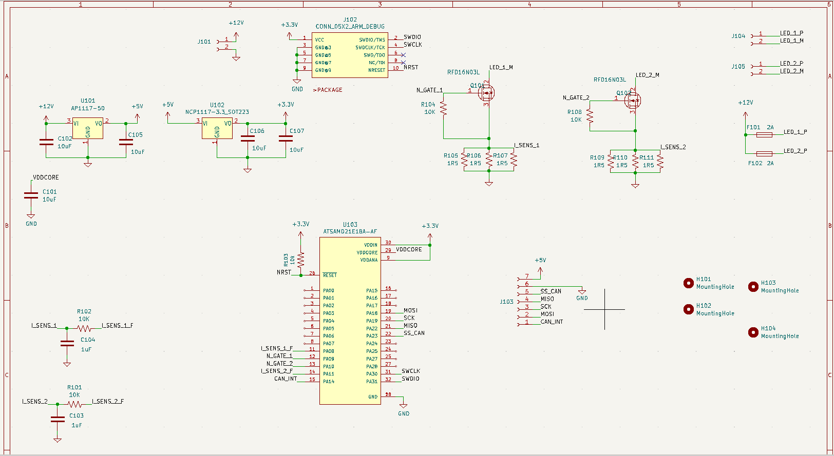
Each light is individually fused and has current sensing. This is so the firmware can detect when one bulb "burns out" and could alert the user. This is not implemented yet in firmware but it is possible.
To mount these bulbs to the frame, I designed a mount that uses zipties to affix to the square tubing. The socket for the bulb was hot glued in such a way that the bulb was held snugly in the mount. I designed the mount to be symmetric for ease of assembly.
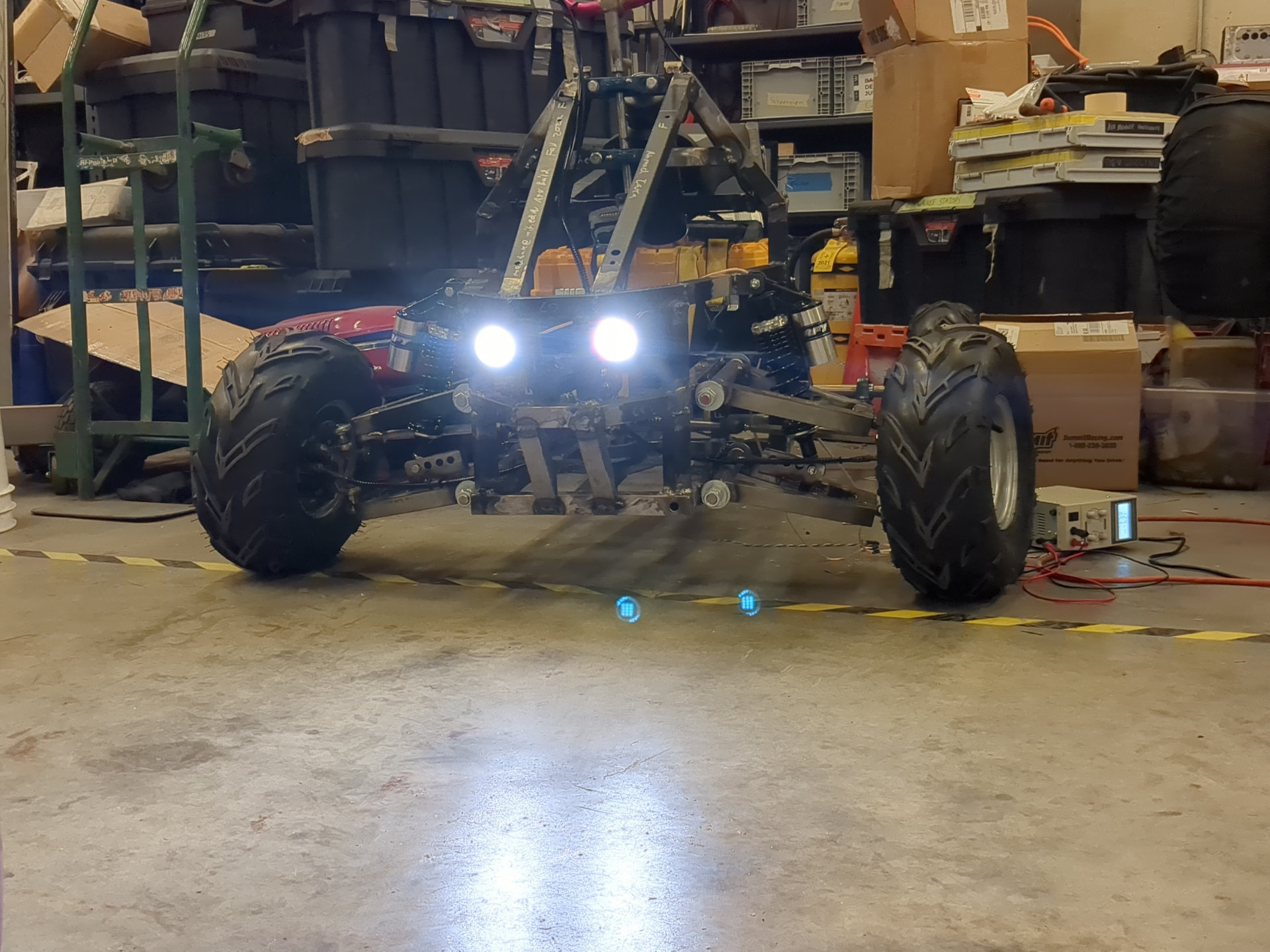
I 3D printed 2 of these and ziptied them to the frame. Because I couldn't resist powering up the lights with a powersupply and seeing how they looked on the frame.


## Rear Lights
I also elected to build the Rear Lights. These lights need to fulfill 4 requirements:
- turn a dull red when the headlights are on
- turn bright red when the vehicle's brakes are applied
- act as turning signals
- most importantly, look absolutely sick.
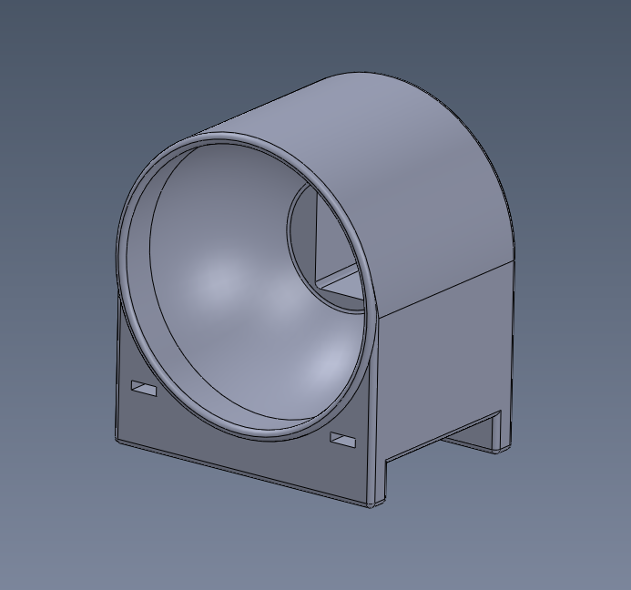
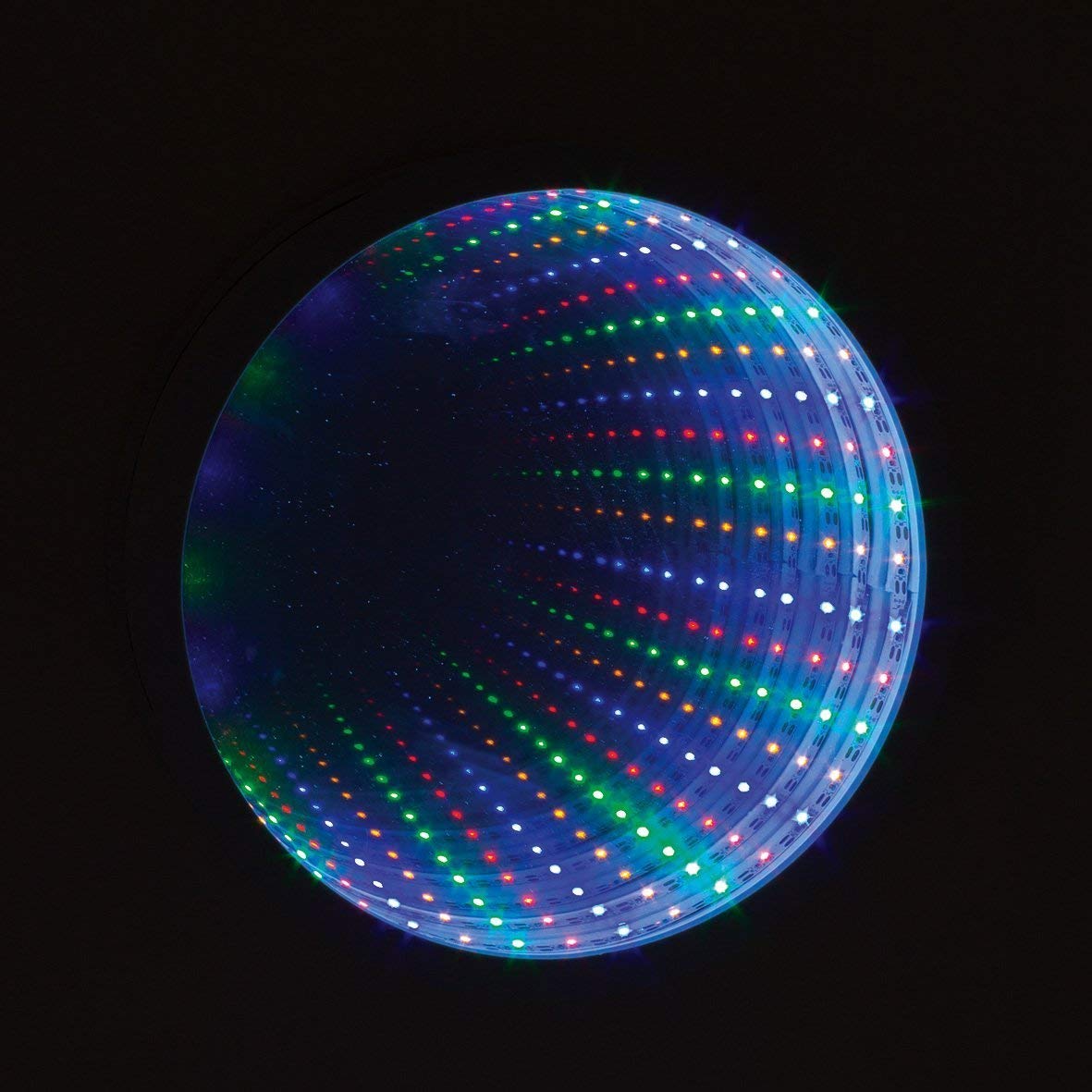
I designed the light assembly to be an infinity mirror. I did this in order to satisfy the last of the 4 requirements.
To do this, 2 types of mirrors need to be used. A fully reflective mirror should be placed on the inside and a partially reflective mirror on the outside. A string of LEDs should be placed in between these two mirrors. Because glass on an ATV is a bad idea, I used acrylic mirrors.
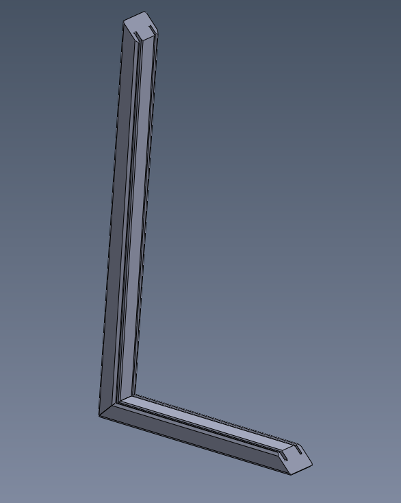
To make a frame that would hold these 2 mirrors in place, I designed a 3D printable piece. To fit it onto the frame, the light assembly had to be rectangular and to fit the LED string, the perimeter had to be less than 3.2 feet.
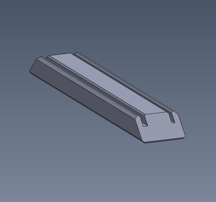
To make sure the angle on the chamfers lined up, I created an assembly with the long side and the short side of the rectangle.
To be able to change the color of the LEDs, The LEDs needed to be RGB. To create the turning signal, I would need individually adressable LEDs. I chose to use the WS2815 LEDs as they run of 12V (meaning less voltage sag). On the same board that controls the headlights, I wrote some state machine logic firmware to control the color and pattern of these LEDs depending on the vehicle state. Below is a video of the fixture signalling a right hand turn:

Below is a video of the fixture signalling a right hand turn while the vehicle is also braking:

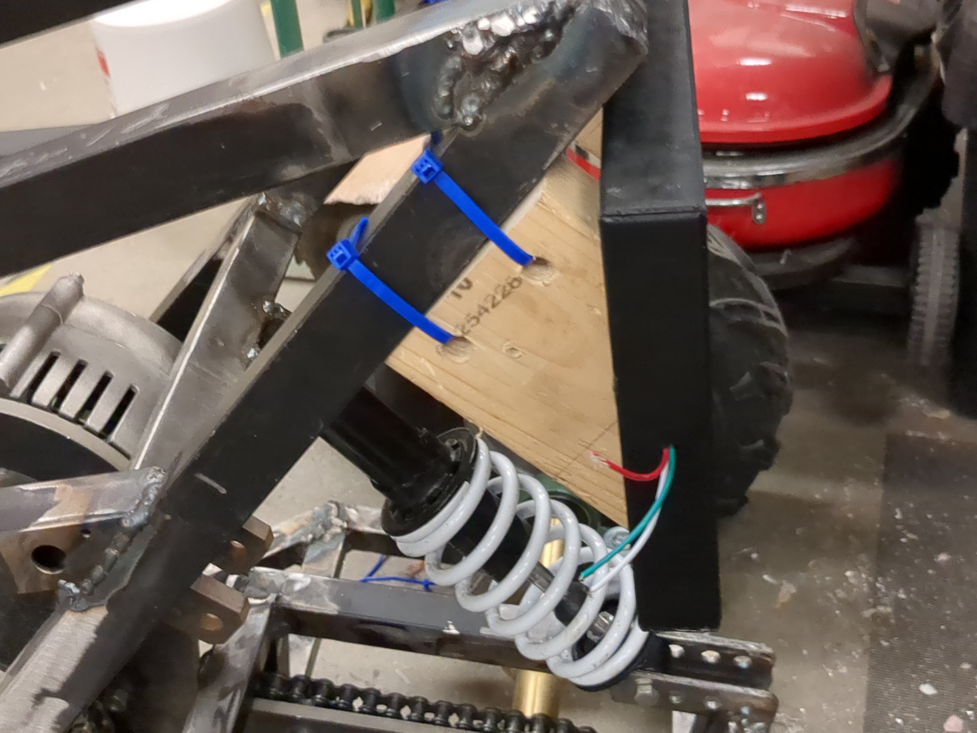
To mount this fixture to the ATV, I again used zipties. I cut a couple pieces of wood at a 45 degree angle and drilled in each 2 holes. I fed zipties through these holes and to the frame of the ATV. I used hotglue to attach the fixture to these pieces of wood.


## Firmware
I wrote the firmare that controls the vehicle's lights. To calculate the color of the LEDs, I wrote a function that sums the red component of the RGB value with the correct red value for the current state of the brakes. This function is responsible for the dim/bright red color you see depending if the headlights are on and/or if the brake lever is pulled.

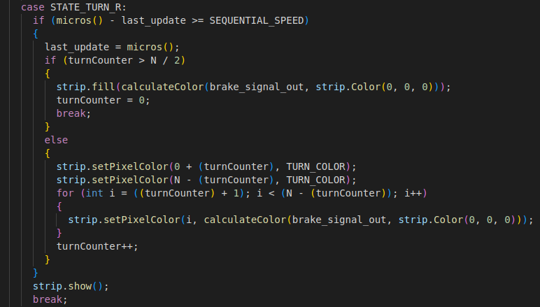
I wrote all the functions of the firmware to be non-blocking and time invariant. I did this to make it easier to add more functions to the code in the future. To create the nice sequential turning pattern, I sequentially fill the strip with the yellow color one pixel at a time every ~4 ms. The rest of the pixels are filled with either black, dull red or bright red.
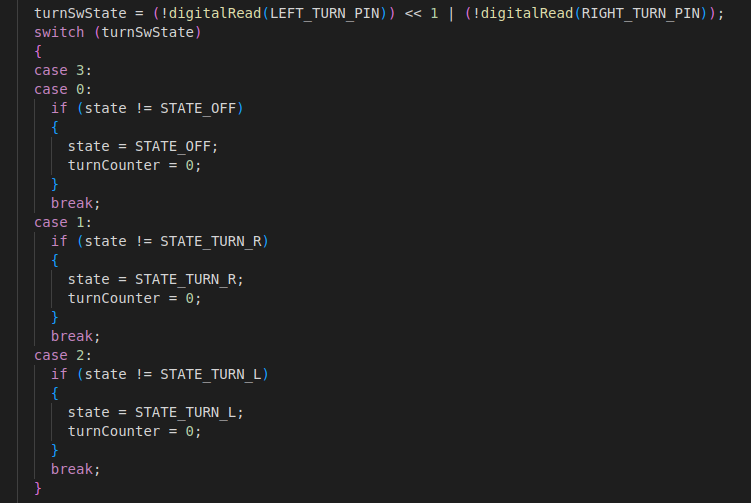
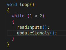
I wrote the input reading as a seperate function to the LED update function. In the following snippet of code, I update the LED state and reset the pixel index depending on the state of the turning signal switches. As a fallback, if somehow the left and right signals are activated at the same time (this should be physically impossible except in the case of an electrical short), the lighs react as if none of the switches is activated.
Writing my code this way allowed me to have a very simple main loop function:
# ∫
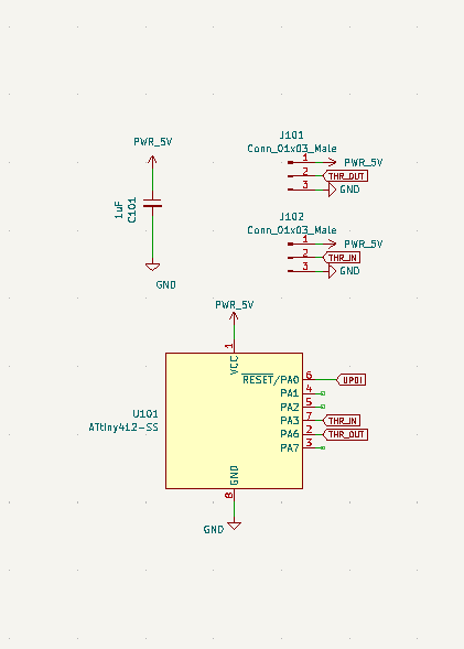
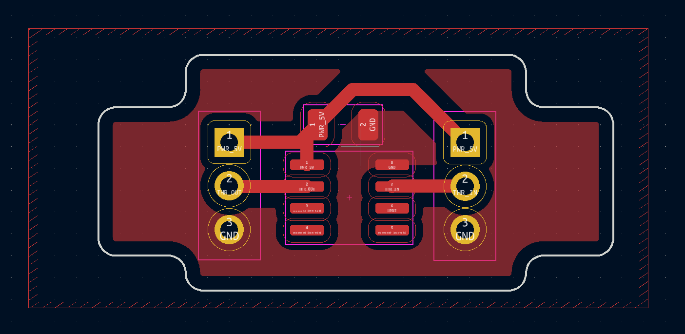
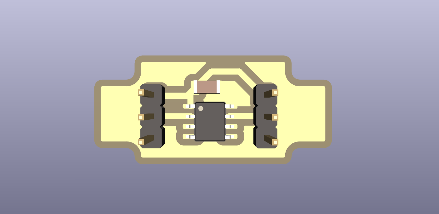
## Throttle mapper
The vehicle's throttle is a grip with a hall effect sensor that outputs an analog voltage between 1 and 4 volts. For some reason the motor controller would not accept this 1-4v signal, so I needed to remap it to be 0-5v. I did this with a simple adapter board and an ATTINY412.
## Bonus: Battery
I did not take as many pictures as I'd hoped while building this battery over the summer. Here are some pics of what I could find:
# Thanks
I would like to give a huge thanks to those who helped me make this project. First to Anthony, Neil, and the rest of the HTM staff. Your support helped to start this project and your honesty kept us on track. Next, I'd like to thank the other students of HTM, current and previous. Learning from a teacher is one thing, learning from your peers is a different level of learning. Another thanks goes to Jack, Dan and the rest of the staff at MIT D-Lab. It was in your shop we spent most of our time working, it was with you we learned to weld, thanks to you this project was possible. Huge thanks to MITERS for donating the motor and controller. Finally, I would like to thank my friends and family for putting up with me through this project.
Done.