**[Raiphy Jerez's site](../index.md.html)**
Personal website for [MIT MAS.863/4.140/6.902(0)](https://fab.cba.mit.edu/classes/863.22/)
Week 3: make an in-circuit programmer that includes a microcontroller, mill and stuff the board, test it to verify that it works
Design files
=======================================
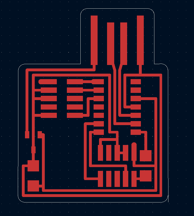
I started by downloading the pcb's gerber files from the course website. I then opened them using kicad's built-in gerber viewer. From there I imported the traces into kicad's pcb editing software. Because only the traces were imported, I had to manually draw the edge cuts. Once I had finished drawing the edge cuts layer, I re-exported the design as gerber files (only the F.Cu and Edge Cuts layers).
Milling
=======================================
To mill the board, I imported the gerber files into the milling software. I had to set a position offset to make sure my board was cut from a piece of the stock material that hadn't been yet cut. I also told the software to give me 5mm of clearance offset. This was to make my job easier later while soldering. This one little setting would have added a long time to the job if it weren't for this one trick. In the list of tools to be used, I added a toolchange to the 1/8th inch endmill. This made it so it would use the large endmill to cut away the large areas of copper and also the edge cuts. This saved at least 10 minutes from the total job time.
Soldering
==============================================
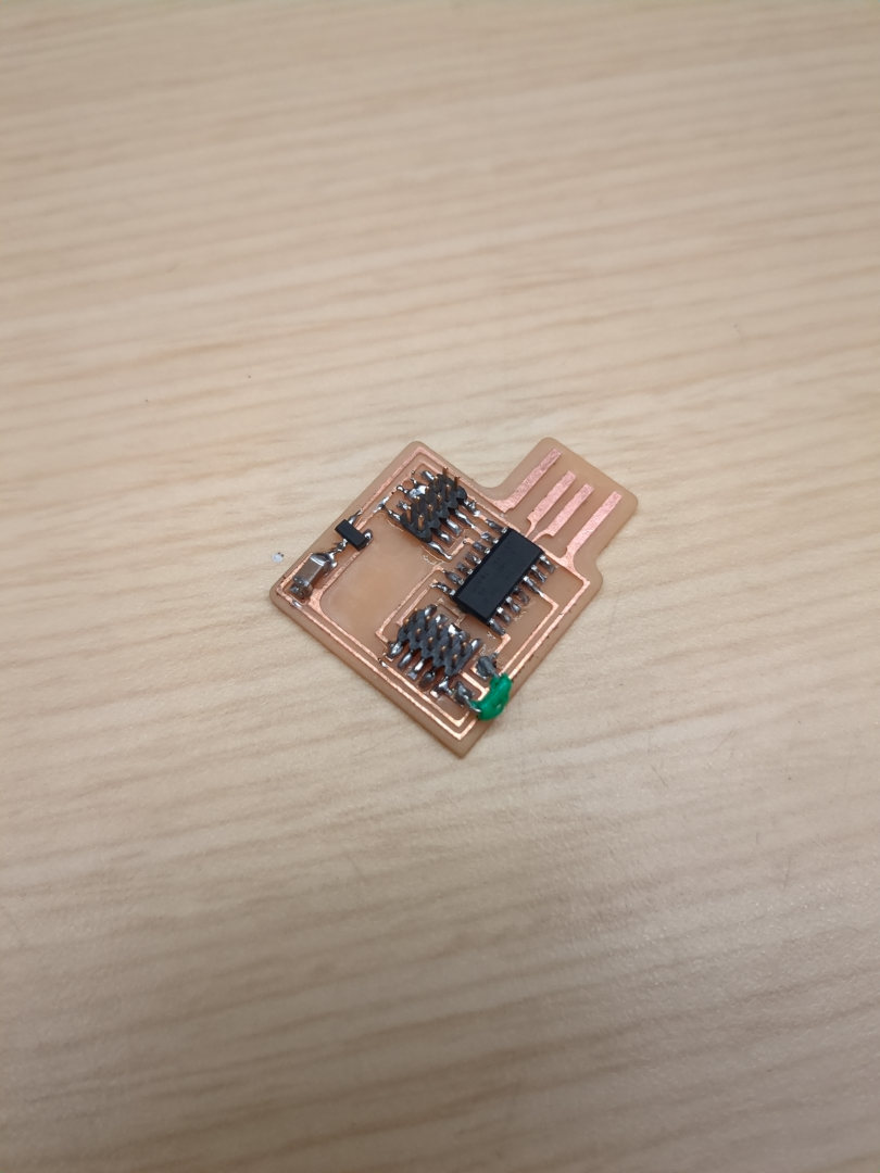
Once the mill had finished, I cleaned the dust from the mill and board and gathered the components for soldering. Soldering was pretty straight forward. I forgot to grab a 0 ohm resistor so I used a piece of jumper wire instead. After I finished soldering I used a multimeter to test the resistance between the 5v rail and GND. This was to make sure there were no shorts. I then did the same with the 3.3v rail for the same reason. After I was sure there were no shorts, I plugged it into my computer and measured to see if 5v/3v3 existed on the board and they did.
Programming
==============================================
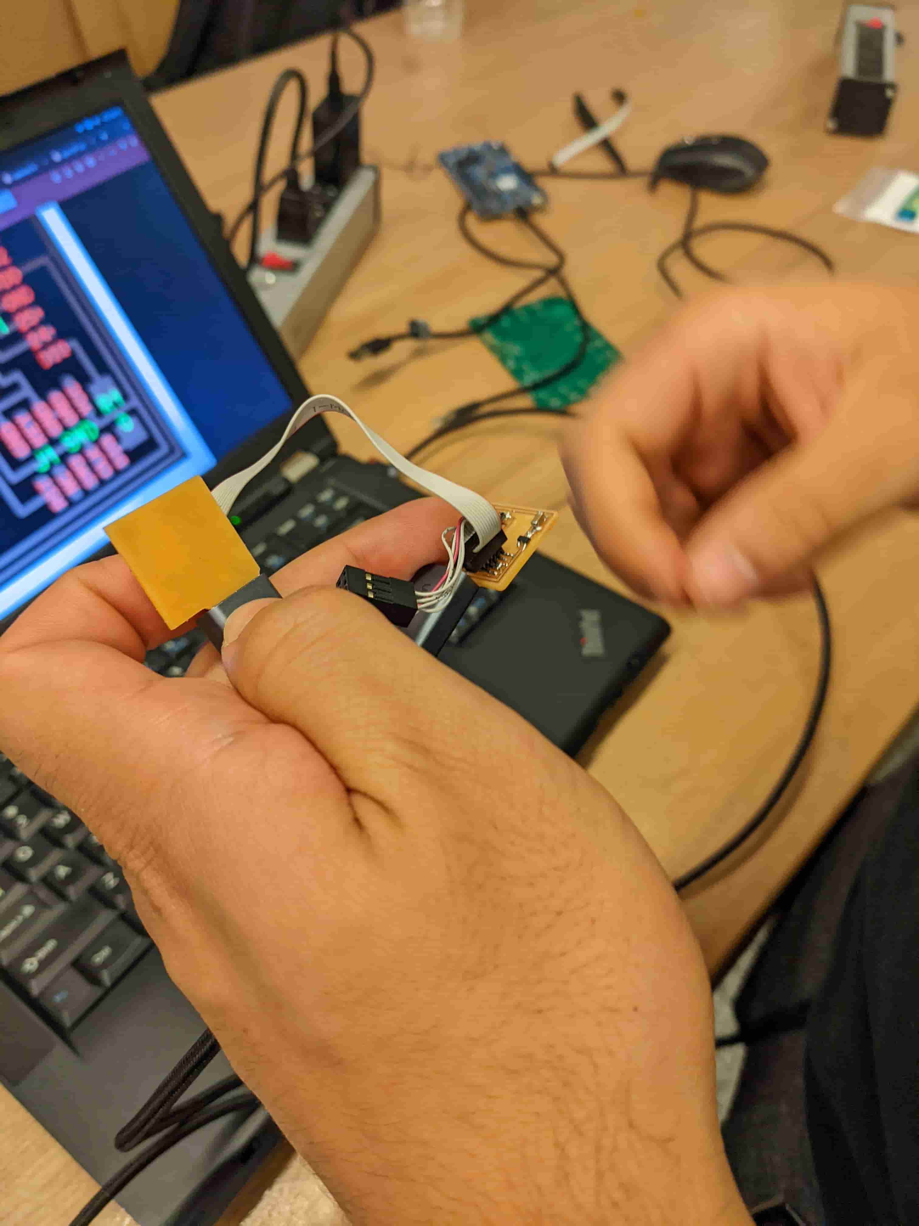
To program the board, I used the edbg executable binary and the ATMEL cmsis programmer. Because there are 2 connector on the pcb and 2 orientations for each connector, there were 4 possible ways to connect the programmer to the board. Initially, none of them worked. I then realized that the board would not be powered from the programmer and had to be powered from the usb port. After trying again, the board responded to the programmer and edbd said it had been successfuly programmed.
Final test
==============================================
To verify the board was now a programmer, I had edbg scan for cmsis debuggers with the board plugged into my usb port. It was detected. I then proceded to program my friend's board with my board and it worked.