Final Project
The Idea: DIY Multi-color 3D printer
Last semester I took 2.00b which is seemed to be the class course 2 funnels all their money because for their learn to CAD assignment they told us to design an enclosure for a music box and to “Remember to add colour since we’ll print these on our Stratasys J55”.
At $300 worth of material for each box times 100 students, they spent $30,000 dollars just making our random creations. Excessive, yeah but results were incredible.
Honestly, ever since using the J55 printing in a single colour on a Prusa has been midly dissapointing. While taking to Anthony about if EDS had any colour printers – it does not :( – he mentioned that some people online have had success using sharpies to dye filament as it left the extruder.
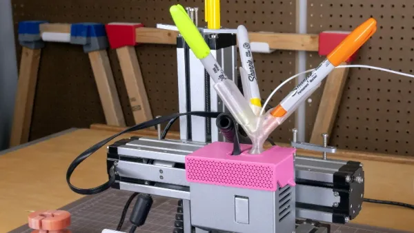
The results from mechanical systems that implemented this are quite impressive.
Effectivly, you can 3D print holders which press multiple sharpies against a white filament entering your extruder.
However, there are issues with this approach
- Resiudal colour. Once the shaprie enters your nozzle it heats up with the filament, and portions of it tend to stay in the nozzle coloring future prints
- Control of the color. Just pressing the sharpies to the filament makes a coloured piece but you can’t print pieces which require certain colours in specific places (e.g. like the box above)
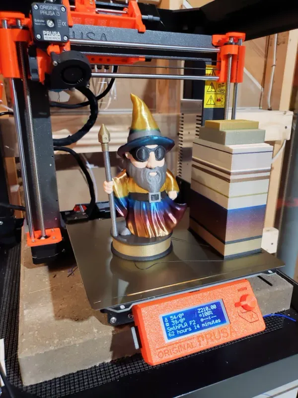
Another way to get mutli-colour prints is to use multiple filaments. Prusa has their MMU2S addon which converts their printers from single-filament into 5-filament machines. While the results are beautiful they’re also incredibly wasteful as they build a “wipe-tower” where they deposit filament during changes
Finally, there are articles online about the daVinci Color a relatively cheap printer which can make multi-color prints in RGB colours without waste. However, I can find very little examples of it being used by consumers rarther than specific review sites. However, it’s approach is what I’m going to try do. They use a special ink absobation PLA filamenet and print inkjet ink on the outer layers of the print.
How will I fund it?
This is definetely going to take more than the 10s of dollars HTMAA offers and as a broke college student I don’t have that sort of money so I’m getting MIT to pay for it through Projx. Specifically I’ve gotten $500 dollars, yay :)
The execution
Planning
At the beginning of the project back in Novemeber I came up with this plan
- Apply for Projx
- Investigate stepper drivers
- Look into printers to modify
- Currently thinking about Ender since it’s so cheap
- Need one where I can add addons to its control board
- Look into inkjet printer head
- Heard from someone that most heads can’t be interfaced with and there’s only one generic one which can. They said this was info from 6 years ago however
- Design inkjet printer gantry
- Build and install inkjet printer gantry
- Write addon for Slicr to use inkjet printer gantry
However, after getting the ProjX funding there was a meeting with the other funding recipents. There I got talking to someone about my plan and they cautioned me against using inkjet printer heads since they are very difficult to hack into. After further conversations with Anthony (during my Midterm review) and Neil (during class after being called on), I decided against using inkjet printer heads
So instead of using an inkjet printer head I decided I should spiral to that eventually. What will be the first spiral?
- Maybe before RGB colors I use felt-tip pens and color in the sides. This would require me to build most of the gantry system and I’d just have to make it modular to take out and repalce
- Mix my own paints (this is what Neil suggested)
- There is an example of this: DIY Inkjet printer
Then on Thingiverse I saw that someone developed the 3D Colorizer, a collection of 3D printable hardware and software which make multicolor prints with sharpies. The results looked great and I decided that I wanted to do something similar. After reading how the 3D colorizer worked and other people’s feedback I saw there was one big issue. It holds it’s sharpie tool change mechanism at the top of the printer, which means every time you want to pick up or deposit a sharpie you have to perform a time consuming z-axis movement.
This would be my first spiral and afterwards if I had extra time I could look into hacking the inkjet printer head.
The new plan
- Pick a printer to design addon for
- Ideate tool change mechanisms
- Aquire a printer
- CAD tool change mechanism
- Install tool change mechanism
- Get printer to talk to tool change mechanism with networking
- Make a Cura plugin to actually move the sharpie around
1. Picking a printer
Anthony was able to source two printers which I could modify: Ender 3 & an AnyCubic Mega S. I’ve used an Ender before but never an AnyCubic so I’m needed to decide between the two
| Ender 3 | Anycubic Mega S |
|---|---|
| Community (Lots of people have hacked Enders, made addons for them, etc) | Has a better heated bed |
| Open Source (open source hardware and firmware should make this easy to work with) | Filament sensor |
Due to the size of the Ender’s community I’ve decided to go with that, if anything went wrong I hoped that it would be easy to find support.
2. Tool change mechanism
There were a couple of requirements for this:
- Has to be faster than z-axis movement
- Has to be an addon for the Ender 3
- Minimize the amount of motors
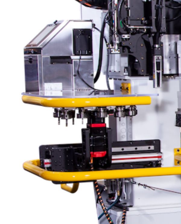
For the tool change I was initally inspired by how the Onsurd in the N51 architecture shop works. It has all the tools on a side-mounted cylinder which rotating cylinder and when a tool change needs to occur it has the effector move over to the side, the right tool rotates into position and then is attached.
My first idea was to try maximize the speed I could color at. I wanted to attach a rotating sharpie tool change to the printer head on the x-axis. The idea was that I’d have a rotating platform which could hold 4 sharpies. The sharpie would rest on top of springs so their tips wouldn’t leave the tool change system. Then in at one location I’d have a solenoid, to use a sharpie the tool change would rotate the correct underneath the solenoid, the solenoid would be activate pushing the sharpie and compressing the spring underneath and the tip would leave the change and be able to be used.
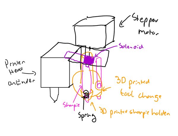
However, I was concerned that the extra servo would add a lot of weight to the printer head which could reduce printing speeds.
So next I thought about just adapting the mechanism that the 3D colorizer uses.
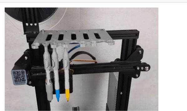
Briefly, at the top of the printer a plate is mounted which contains gaps. Each shaprie is given a cap which can fit inside this gap, so you can suspend shapries from the top of the printer. The printer’s extruder is given a shaprie holder which it uses to pick up these sharpies.
In this version I would mount my tool changing cylinder to on the end of the x-axis gantry. Then I would give each sharpie a cap so they would sort of dangle (but securely) from the tool change system. On the printhead I would have a cup attached to the side connected to a small servo, when I want to engage a sharpie I would have the printhead come over to underneath the sharpies, the servo would raise the cup to displace the shaprie cap from the tool change, I’d move the printhead back to position and the sharpie would lower to start coloring in.
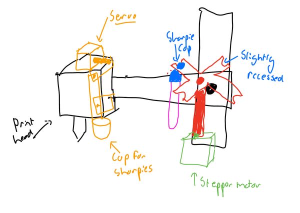
The major pro was that I had already cadded the sharpie holder for machine building week.
However, this would of required a second motor (in this case the hobby servo) and I was unsure about how stable having the servo convert it’s rotational motion into vertical displacement would be.
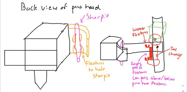
Finally, I thought up an idea to do everything from one roating action – flextures.
On the print carriage instead of a cup I would have two flextures. Small arms sized for the diameter of the sharpie which the sharpie can “click” into. Similar, but weaker flextures would be present on the tool change. When I want to put a sharpie on to the print head I would move the stepper such that the both the arms of the tool change flextures and the print head flexture face the same way, then the sharpie will be pressed against the print head tool holder constraining it’s movement but the stepper will still try moving so the the sharpie will pop into the print head flexture and out of the tool change flexture.
For the reverse action, going from the print head onto the flexture, I would move the motor in reverse, except this time the tool change flextures will be the piece applying pressure, pushing the shaprie out of the extruder but first onto the tool change flextures since they are weaker.
Parts that I need
The hard deadline for getting parts for the project was Dec 9th so I had to come up with a list. Niel had said that we could only get parts off the Fab Inventory list but Anthony then told us that the lab had some money to buy other stuff, yay :) so I got
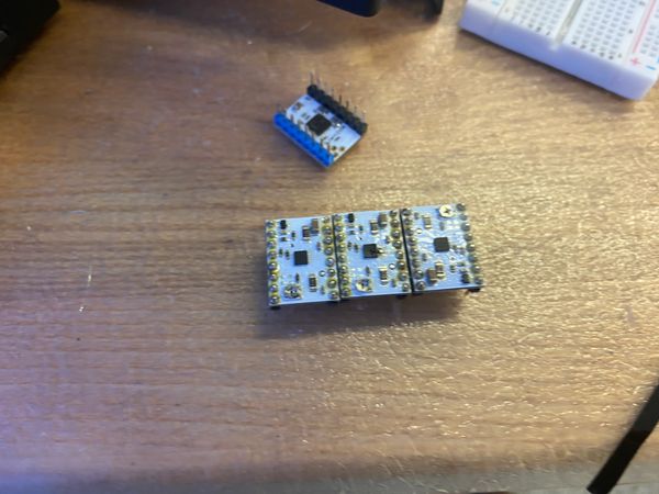
- ATSAMD11C
- Stepper Motors (To rotate the tool change)
- TB67H451FNG (Stepper driver)
- Nylon filament
- I had heard that it absorbs inks better than PLA, but I just wanted to check if EDS would by any chance have some already, I could test with.
- Sharpies
Acquire and fix a printer
Now that I had decided to use the Ender 3 I went over to EECS and picked it up.
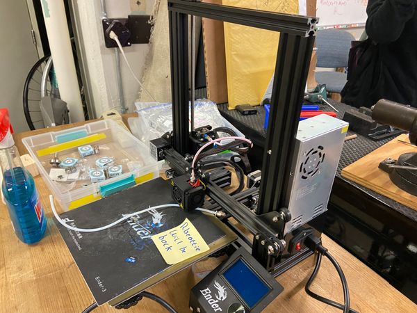
It used to belong to a professor and he no longer needed it so I wasn’t surprised whenm, when I plugged it in and started a print job it starting smushing the nozzle against the printer bed. Oh no, calibration time I guess.
There were a couple of issues that I needed to fix. First was the bed level, it was everywhere. I took a level meter and the bubble went straight to one side. Underneath the Ender bed there are four springs – one at each corner.
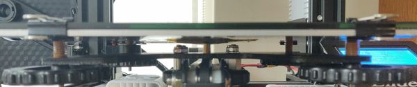
I moved the nozzle to each of the corners and adjusted these until the nozzle was flush. Unfortunally even after doing this the bed was still unlevel, and given that this wasn’t my final project and I wanted to move on as fast as possible I bought the BL Touch which is an inductive probe for automatically detecting the bed level. In my hurry however, I didn’t realise that I bought the probe for the Ender v 4.2.2 motherboard however while the Ender I had had the v 1.1.3 Motherboard, thankfully the Endergerton student center had a spare Ender just lying under a table which had the more recent motherboard so I was able to salvage that. This I thought would also be generally useful as the v4.2.2 I had read was easier to interface with.
Installing the BLTouch was realatively easy, I followed along with Creality’s guide for the v4.2.2 motherboard. It roughly involved:
Installing the bracket:
- Insert the BLTouch into the bracket
- Install the mount on the Ender hotend
- Connect the attached cables to the BLTouch
and then I had to remove the Z endstop since the BLTouch would otherwise conflict with it. Next I needed to disconnect the Z endstop from the motherboard ( (ughhh which involved unscrewing it right after I had just rescrewed it from changing the board) and plugged in the BLTouch.
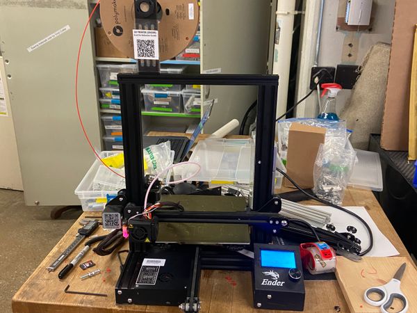
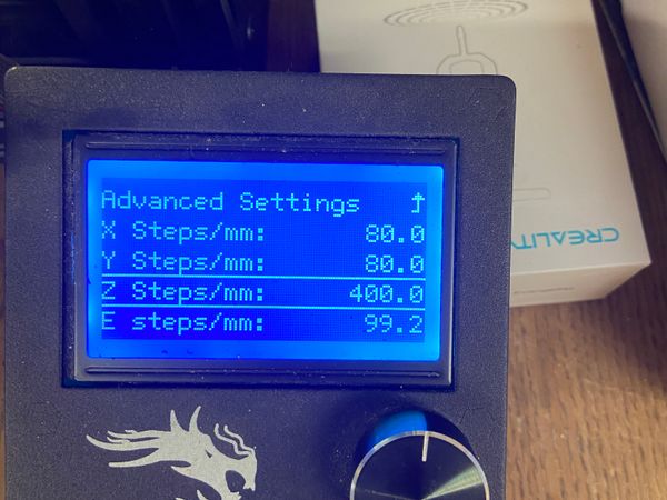
Things still didn’t work however and the printer was still under extruding, after thinking what it could be I decided to check how accuratly it was feeding the extuder. I measured out 100mm on the filament with and then told the printer to extrude 100mm. Then I measured how much was actually extruded. It was awful! It only did 30mm. Again I went back to Edgerton’s spare Ender and salvaged it’s tensioning system for the filament against the bowden tube to replace mine with.
Once done, it started extruding correctly, and I only needed to do a small change to the e-steps to get everything working.
Finally it was time to print a calibration cube and it worked!
CADing the tool change mechanism
For the tool change I first searched for a reference CAD file of the Ender 3 however I found nothing, so I copied over the sharpie model than I had previously found for machine building week.
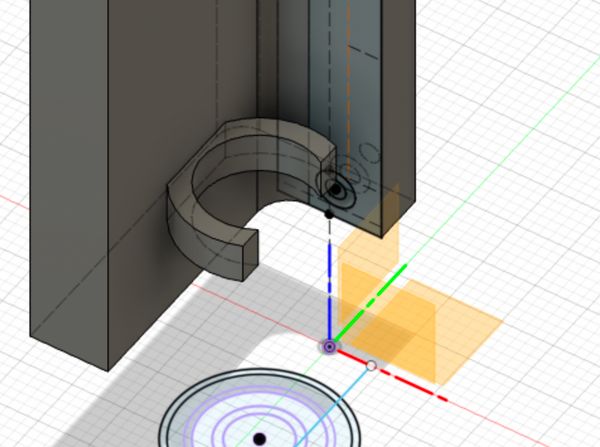
The first step was to design the flexture that would attach to the printer carriage. On the right side of the printer carriage there is a cold-fan which is attached with 4 screws, my idea was to switch two of them out for longer screws and attach my sharpie holder there.
I got out a pair of callipers, measured the size of the screw holes (M3) and the distance between the holes and added all that info into a Fusion sketch.
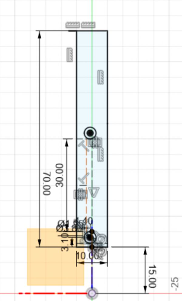
Then I extruded this sketch and extruded a back wall for the sharpie to press against
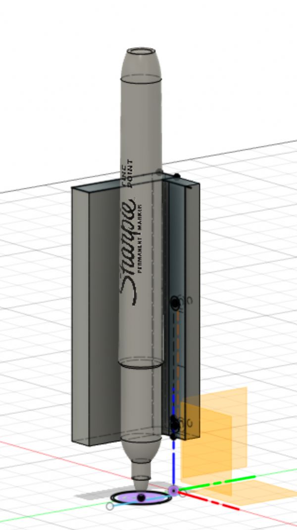
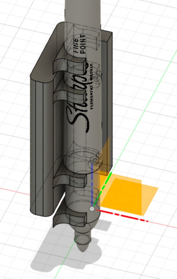
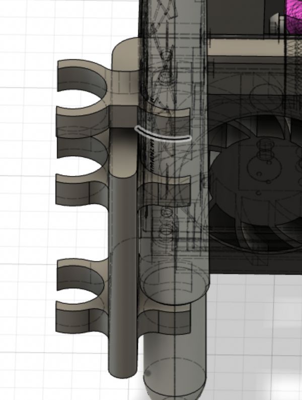
Now it was time to create the flextures. Thankfully, in machine building week I had confirmed that the GrabCad model I had found was the correct sizing as the sharpies which I had. Tolerances and fits were going to be key here to get everything to work. I created a new sketch and projected the different circles of the sharpies for it’s varying radius along it’s length. Then I offseted the second to largest circle (corresponding with the lower radius of the sharpie) by 2mm for the thickness of the flexture and extruded it with a height offset to go flush against the sharpie.
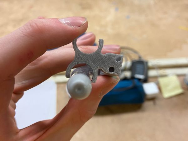
Of course, once I had a flexture made I instantly started printed them for testing. Throughout this whole process I kept going back and changing the offsets to optimise the flexture
I repeated this process for making a flexture for the top of the sharpie except this time using the largest projected circle.
Finally, as they are above they won’t bend well and actually would probably just snap off since they’re attached to rigid wall along one line. Instead I filleted them to improve their bending and strength
With this done it went off the printer and I started working on the flextures for the tool change system.
For these one I simply created a new sketch, projected by own flextures, offset them by a little bit (~0.2mm) and extruded them with height offsets so they would be above and below the effector.
Then I sketched some rectanglaes to connect both the bottom and top flextures together while still leaving room for the effector so that the tool change could pass the effector after it deposits the sharpies.
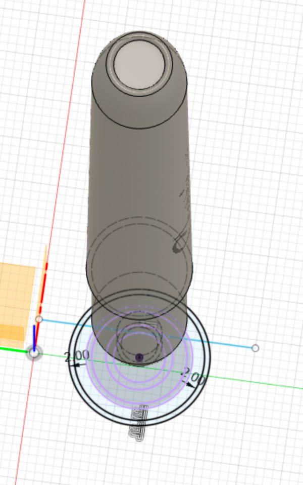
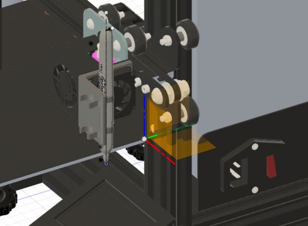
Now I could design the tool changer. First I measured the available distance that I had between the maximum X position on the Ender and the rail that the X-axis moved on (35mm) and then I created a circle of 30mm to leave a little room to avoid butting into it. I made the circle tangent to one of the flextures to maximum space but ensuring the sharpies would not hit into them. Then I created screw holes for M4 bolts (Metropolis ran out of M3) and cut through both the extruded circle and the tool changer flexture bit. In the flexture bit I cut out a another slightly bigger hole for the cap of the screw to fit into. Then I mirroed both the circle and the screw holes to the bottom and joined them with a hallow cylinder – hallow so that a rod could fit into it to restrict any lateral movements while rotating. I circled patterned all the screw holes so that I could store four sharpies and finally I measured the diameter of the spoke on the stepper motor and create a hole that size with a small offset for a press-fit attachement.
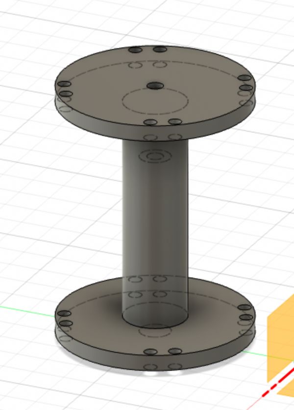
Then I circular patterned the tool change flexture bit around to see how it would look all together.
Communicating with the printer board
Once all the CADs were done I put them on printers around campus (I think at one point I had 4 prusas going), and I switched to looking into how I could get the printer board to move the extra stepper in responde to GCode. This part was a little contrived since to complete the assignement I needed to mill and use my own boards as much as possible, although having a way which doens’t use up scarce pins on the motherboard would be very cool.
After looking into what communication methods the printer board can use I saw that it talks with the LCD screen over I2C. Having previously done this in networking and interfaces week I thought I’d try do it again.
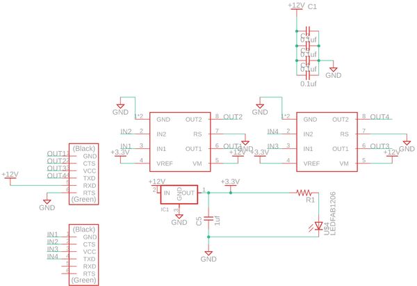
First up I found a reference schematic for the board online
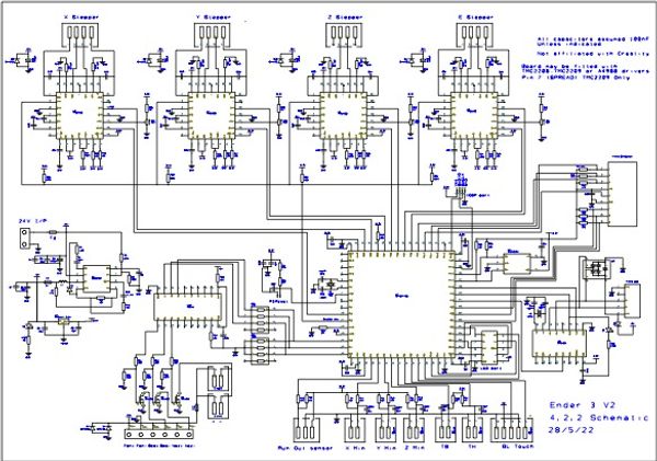
this was unfortunately not very useful as I couldn’t find a version of it after being routed so I didn’t know if all the pins it gives to the LCD stay in that order in real life. Instead I found an instructables of someone who was chaning out the LCD screen and they had this handy image:
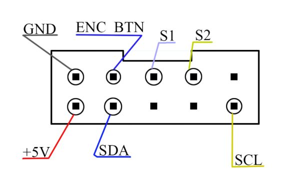
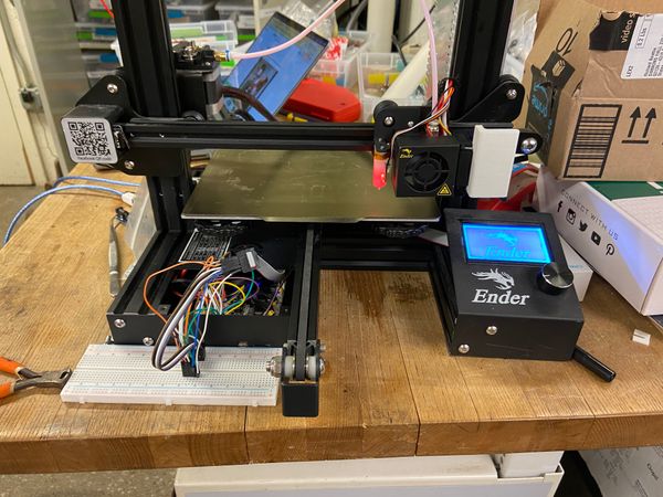
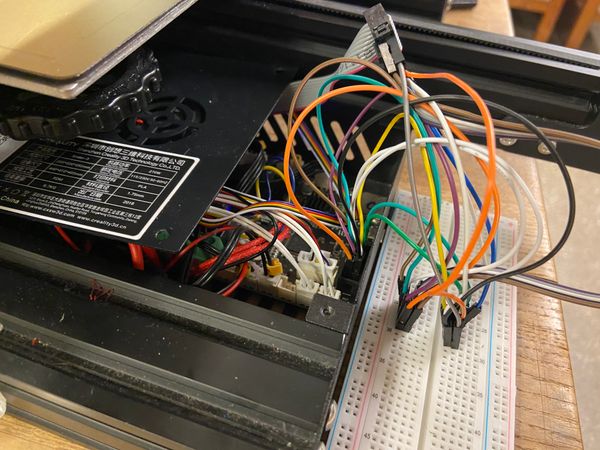
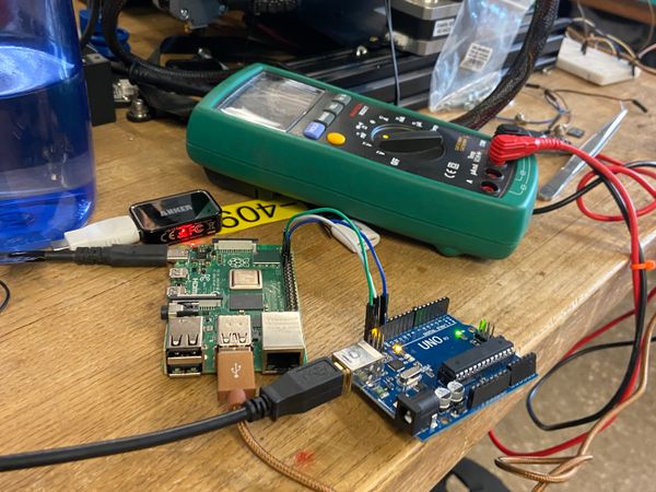
which told me where was SDA and SCL. Unfortunally, I spilled my water in my backpack a couple of days before this which fired my dev board (:() so I decided to first test everything with an Arduino Uno and once I got it working I’d switch to one of my own boards. I broke out all of the LCD pins to a breadboard and I then connected the SDA and SCL lines to both the LCD and my arduino.
Then I powered everything on and suddenly there was htis insistent clicking sound. For whatever reason, the arduino was making the board think that I was always pressing the knob.
I tried chaning the wire, using a Software Serial library, and adding my own pull up resistors but whenever I’d activate the I2C on the Arduino the clicking would appear.
Alright, I thought, this is annyoing but I should still be able to test this. As a barebowns test I found some code online that turned the arduino into an I2C sniffer to read traffic on the lines without influncing it itself. This worked and I could see when the printer was powered on the LCD started talking.
With that done I wanted to see if I could set up the arduino as a secondary device, but first I would need the printer to be able to send I2C commands.
Upgrading marlin
The Ender’s run Marlin (a printer firmware) which has experimental support for I2C with the M260 gcode command. However, it is behind a feature flag which meant that to use it I would need to upgrade my firmware.
Thankfully there were a couple of videos I could follow along with:
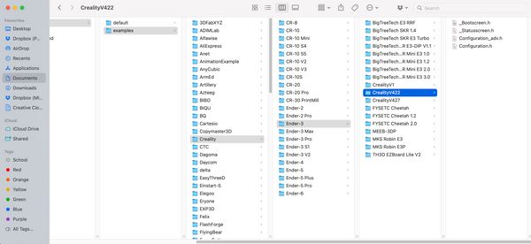
First I went to the Marlin website and downloaded the firmware, along with the configuration files. After extracting the respective folders from each zip file I went into the configurationss folder and then the example subfolder, found the Ender 3 and copied over all the files for the v4.2.2 board
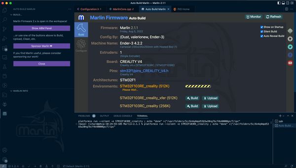
Once I had all these files I needed to switch some settings. I use VSCode and Marlin has also made an extension which takes care of compiling the firmware. With that installed I opened up the Marlin folder and opened the Configuration.h that I had just copied over and adjusted some settings”:
- Find and uncomment
#define BLTOUCHfor my BLTouch sensor - Comment out the
#define Z_MIN_PROBE_USES_Z_MIN_ENDSTOP_PINsince I removed the Z endstop - Uncomment
USE_PROBE_FOR_Z_HOMINGso that we can use the BLTouch for homing instead - Uncomment the
#define Z_MIN_PROBE_PINline- This is the pin which are probe is attached to, in the case of the Ender 3 with the 4.2.2 that’s
PB1
- This is the pin which are probe is attached to, in the case of the Ender 3 with the 4.2.2 that’s
- Update the
NOZZLE_TO_PROBE_OFFSETto{ -44, -9, 0}which is the default offset for the bracket which came with the BLTouch
With all the neccesities done I added a new line #define EXPERIMENTAL_I2CBUS. Then I opened up the Marlin VSCode extension and compiled the firmware.
With that I moved the firmware onto a microsd card, put it into the Ender 3, powered it up and let it flash. Everything worked, and it was time to test I2C with the Arduino. I wrote a test .gcode file with the example code from the Marlin website
M260 A08  ;
M260 B77  ; M
M260 B97  ; a
M260 B114 ; r
M260 B108 ; l
M260 B105 ; i
M260 B110 ; n
M260 S1   ; Send the current buffer
and uploaded some code to the Arduino to output to the serial monitor if it got an I2C message
#include <Wire.h>

void setup(){
  Wire.begin(8);
  Wire.onReceive(receiveEvent);
  Serial.begin(9600);
}

void loop() {
  delay(100);
}

void receiveEvent(int howMany){
  while(1 < Wire.available()){
    char c = Wire.read();
    Serial.print(c);
  }
  int x = Wire.read();
  Serial.println(x);
}
Then I uploaded the code, transfered the file over to the microusb and ran the gcode. And…nothing. No sign that it sent any commands. I spent the next while sniffing the I2C again, reflashing the firmware, and googling to see if anyone had ever done this. Apparantly not.
After trying in vain for two hours to get I2C to work I posted a question about my situation on the 3D printing stackexchange and reddit.
- StackExchange How to send i2c commands from creality 4.2.2 board-with marlin
- Reddit - Sending I2C commands with the v4.2.2 board
I went to sleep after writing those questions and when I came back I still had no replies so I decided to switch tatics. I researched a bit about Enders and I found that many people set them up with OctoPrint and / or Klipper. Klipper in particular is a really interesting new way of running 3D printers (effectively a computer takes care of the path planning and simply instructs the motherboard to control the steppers rarther than giving the motherboard the gcode). However, it doens’t easily support adding custom plugins to. Octoprint on the other hand does.
OctoPrint has a feature called action commands which I initally thought were going to be the perfect option. They allow octoprint to run arbitary script files in repsonse to a command. However I misread the description and actually they are for the printer talking to octoprint rarther than commands that happen when octoprint reads GCODE. For that, I would need to use @ commands. Unfortunally, it is not possible to set these up through the GUI like action commands but instead I would have to make a plugin. I briefly skimmed the documentation for that but decided to hold off doing it until I had other stuff ready as my prints had been well completed by now and there were other stuff to do.
Instead, I decided to just get the Raspberry Pi talking to the Arduino and Octoprint setup so once I needed to make the plugin all the boilerplate would be done. Setting up octoprint was super easy, Raspberry Pi now has a dedicated program for installing all the different operating systems available for it. When I first got a Raspberry Pi like 10 years ago I remember being super sacred about the whole flashing process, especially with downloading the firmware from different websits, running these really old programs, and always if I had accidently selected my harddrive instead of the sd card. The Raspberry Pi Imager utility makes all this super simple, once installed I just opened it up, selected OctoPrint, and it installed everything.
Once OctoPi was installed I sshed in looked up what were the I2C pins on the Raspberry Pi I2C pins and connected those to an Arduino. Then I wrote a simple C script to use the wiring library and send data over I2C to the arduino
#include <iostream>
#include <wiringPiI2C.h>
#define DEVICE_ID 0x08
int main (int argc, char **argv)
{
    int fd = wiringPiI2CSetup(DEVICE_ID);
    if (fd == -1) {
        std::cout << "Failed to init I2C communication.\n";
        return -1;
    }
    std::cout << "I2C communication successfully setup.\n";
    // Send data to arduino
    uint8_t data_to_send = 17;
    wiringPiI2CWrite(fd, data_to_send);
    std::cout << "Sent data: " << (int)data_to_send << "\n";
    return 0;
}
After uploading, it worked!
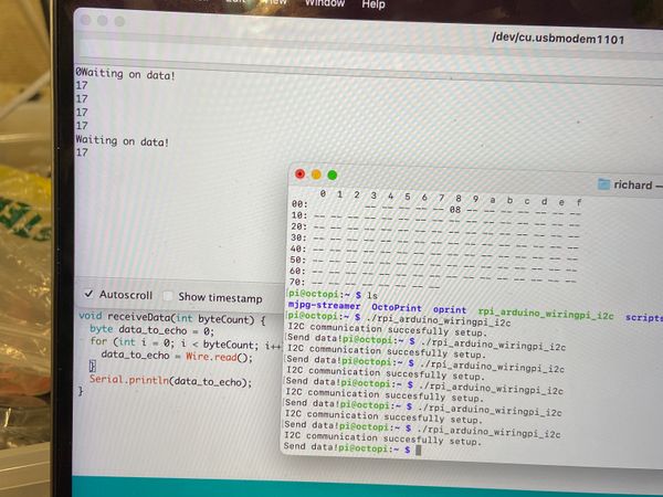
Now with a script that could do I2C communication I can make a plugin for octoprint which will add a new gcode command @toolchange which would run this I2C script and hopefully eventually move the stepper motor
Updating my CADs
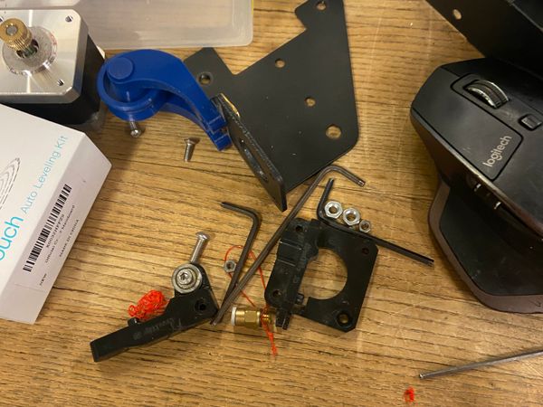
During all this nonsense my prints had just been lying around so now I was ready to try to integrate them into the Ender. First up was the end effector. I had unfortunally never measured the size of the screws already in the cold fan, they are tiny! This meant that they wouldn’t fit both through the fan case and my new 3D printed part. I went looking through Edgerton and couldn’t find one, likely since Ender uses metric (yay) but Edgerton uses freedom units (a.k.a imperial). I found the closet size I could but it was widly too long, so I set out trying to cut it. On Saturdays, Edgerton does this informal “Saturday Thing” event where’s there is always a lot of people around and one of them recommended that I could use a wire cutter but to be careful about cutting the threads.
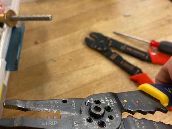
He was right, once I found a sharp wire cutter it was super easy to cut the screws but everytime I’d always do it in the wrong place and make the screw unusable. I was definetely too tired cause I spent an hour just trying to make 4 screws of the right size.
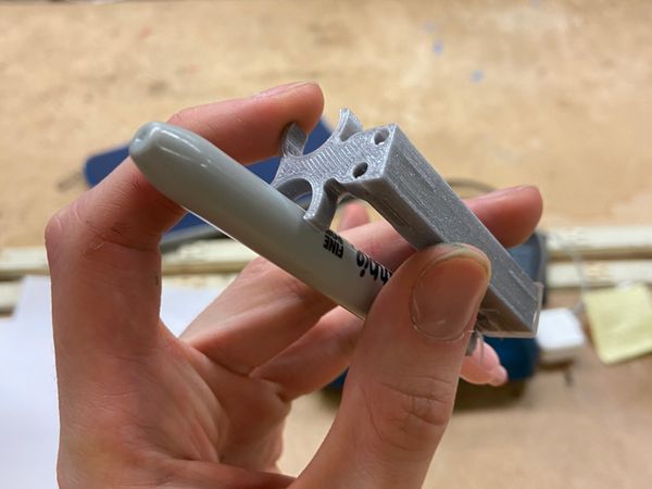
When I eventually made the right size screw I got it through both holes and attached the effector to the printer assembly.
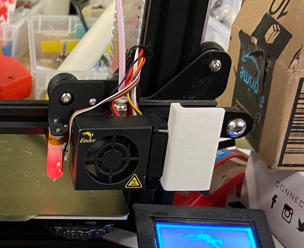
Then I performed some hand tests with the effector and sharpies and the flexture tool change bit. Unfortunally during this, I broke one of the flextures on the effector and had to remove it. Due to the very hacky way I made these screws one of them broke inside the hole and I wasn’t able to get it out. So for the next version I used superglue.
This was a mistake. So the fan has a cover which is pressfit into the actual casing which is screwed in, I superglued my piece to the case which meant once it was pressed with the case the cover came right off and the effector went flying around the room. At this point, I know that my current method wasn’t going to be rigid enough and I needed a new design. I thought instead of mounting on top of the fan why not mount underneath? I tried doing what I did before and just measuring the distances between the screws but this was a nightmare given the small space, instead I went back to google and tried out some new terms to find a CAD of the Ender. And I did! Someone found all the Ender 3 parts and turned them into a Fusion project: Ender 3 Fusion File. With this I knew I could quickly remake my parts and have them be better sized and more rigid. At the same time I realised that my flexture bits for the tool change weren’t going to guarantee that the sharpie is deposited and collected. See currently the sharpie is guaranteed to be collected since the flexture bit can come from behind, engage first (since it has weaker features) and then remove the sharpie
However since the flexture bit is weaker it’s likely that when it tries to deposit a sharpie (by moving in the reverse direction into the effector flexture) it’s flexture will give first from the force of the effector and the sharpie will just pop out. So I ideally need a setup where there are mirrored flextures.
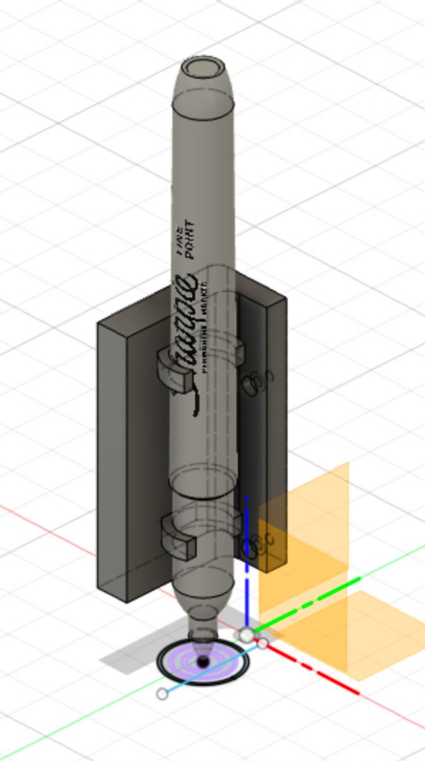
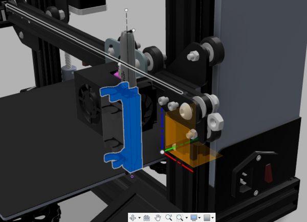
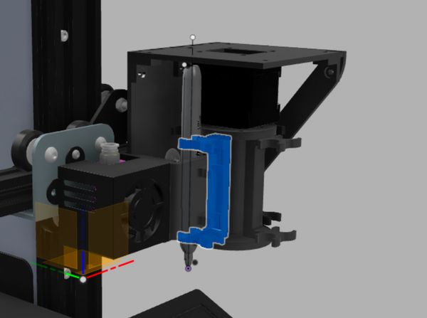
First up, I designed a new rigid effector. First I quickly selected the profile of the side of the fan and extruded a new body based on that. Then I extended it a little on the size and aligned the fan with the new side so I’d have accurate sizes for everything. I then extruded sideways, imported the sharpie model and put a little away from the fan. Then like before I projected the crosssections of the sharpie and used to make the flextures (tweaking the offsets with the results of the first couple of attempts)
Then I created an offset plane in the middle of the wall the flexture was on and mirroed the flexture across this
It was a lot nicer once I had the reference CAD to design the part, I instantly knew when pieces where likely to hit the screws or not be low enough, etc.
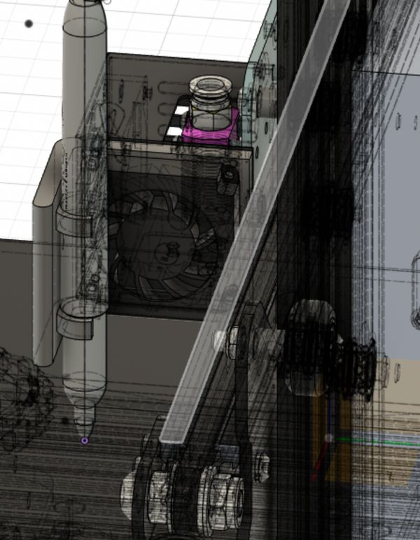
Next up was redesigning the flexture bit for the tool change. Again I projected from the flexture on the extruder and then offset by 0.15mm to make this flexture weaker. This has the added bonus of ensuring that if everything is placed correctly, the flexture bit should line up with the printer head when it is in the maximum x-position (something which was a lot easier when I could just move the component inside Fusion). Once projected, I extruded it (with a height offset) and then mirrored it so I’d have one on both sides.
Then I added a smaller flexture for the bottom of the sharpie, extruded out the side of the top flexture and down to join the two (like before where there is a gap), and then extended the spine on both sides to improve the strength. I then went it and filleted all the corners to make the piece had the maximum strength for all the sharpie deposits and collections.
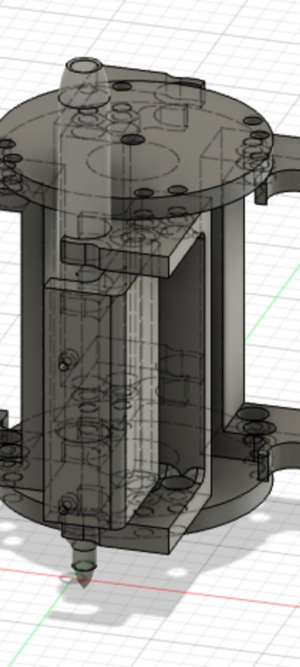
Then I needed to cylinder. Like before I sized the circle such that it got close but was still offset from the frame of the printer. I found a model of a Nema 17 stepper motor on GrabCad and imported that into my design. I got the shape of the cylinder by drawing a 2-point circle from the edge of the tool change sharpie holder to a point offset from the edge of the x-axis to make sure that everything would fit. To get it to work with the Nema I first needed it to hold the motor (so I projected the motor’s screw holes) and had a place for the motor’s spoke (so I combined the motor with my cylidner but kept the tool to have the motor around). Once done, I circulared patterend the sharpie tool holder.
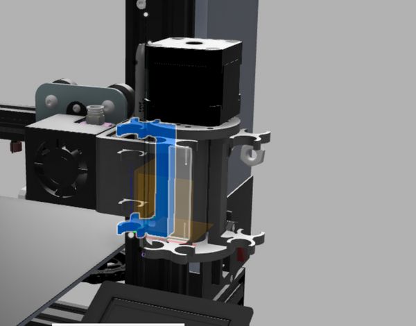
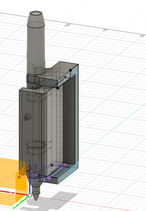
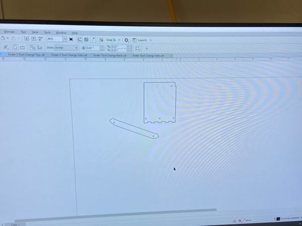
Finally, I needed a way to hold all of these components, since 3D printing takes forver I realised that for these parts I could just laser cut them and so ensured to make everything flat. I designed a back and a top again using the reference Ender 3 and Nema for sizes and then cadded some small brackets to improve stability. As I went for a canterlevered design, I also designed an angled brace.
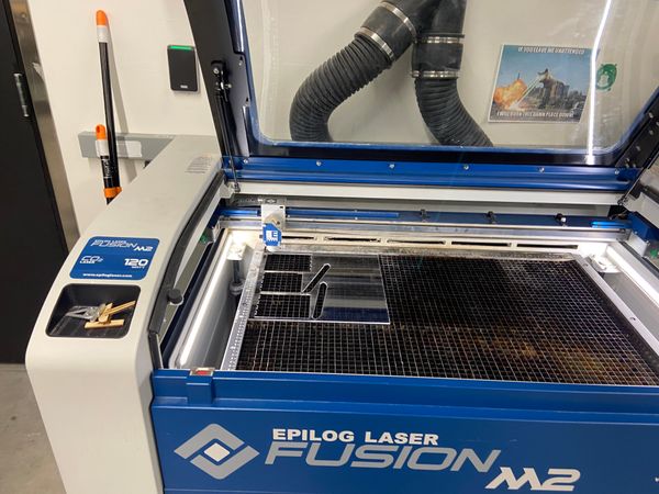
Laser cutting
I put all the files on again 4 different printers in all the makerspaces I’d tap access to and then went to the laser cut. Carl (Metropolis’ awesome laser cutter), did a standout job as always even if I kept exporting my files wrong. I was able to use the same .dxf converter I used during laser cutting week and it still remembered Carl’s kerf and calibrated for that
Making a stepper driver
This I hoped would be a super quick part of the project. I’d say this is Niel’s 80-20 rule but honestly everything with this project went wrong and went extremely over time. I had previously designed a stepper driver for output week and then had updated it during networking week to remove the serial connector and instead have the D11C’s I2C pins exposed.
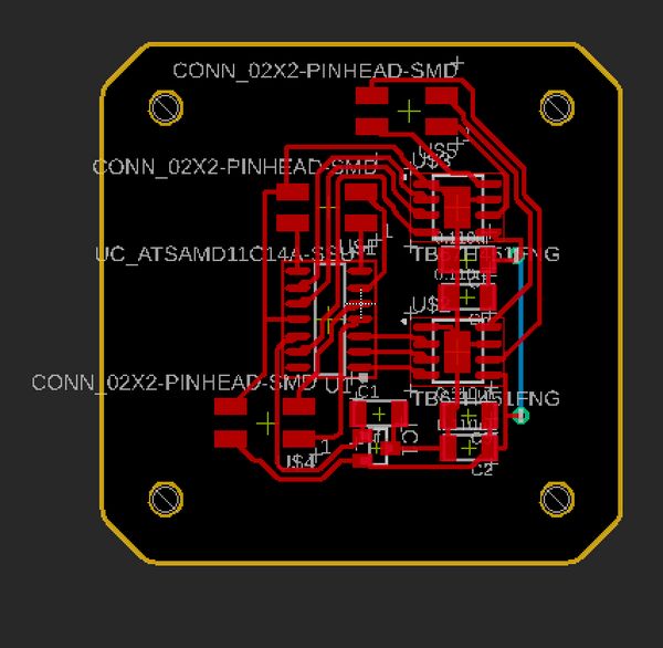
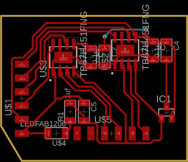
I wanted to integrate the board into the stepper motor similar to have it can be done with the modular machine stepper motors. I knew that Fusion360 had a 3D pcb feature but had never used it and this seemed like the perfect option. It’s awesome (well almost but back to that later).
I went into my fusion file, selected the face on top of the motor and clicked Create>Create PCB>Create assocaitve pcb. Then I went into the 3D file and made a PCB hole where there was previously a 3D hole.
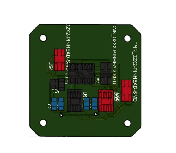
Unfortunally when I stuffed this board and connected it to my stepper nothing worked. I spent some time debugging but couldn’t find anything and so went to Anthony. He found that my VREF pins on the Toshbia H-Briges were getting 5V. This shouldn’t of been possible the logic level of the system was 3.3v so the existence of 5V basically guartanteed that my D11C had been fried.
After continuously changing components and soldering and unsoldering I found that when I had only one of the H-Bridges everything worked but with two the 5V would appear. Eventually, after so much debugging Anthony recommended that I start over. So I decided that instead of using that stepper driver I would remill my dev board from networking week and connect it to a stepper driver breakout board.
I set up the milling job on the OtherMill and routed my breakdown while it was running
Then I went to the Archshop and started soldering it, but it was late, and I was tired so like always, everything went wrong. Namely, I burned my finger and ripped up some traces. At this point I gave up on the Toshiba HBridges
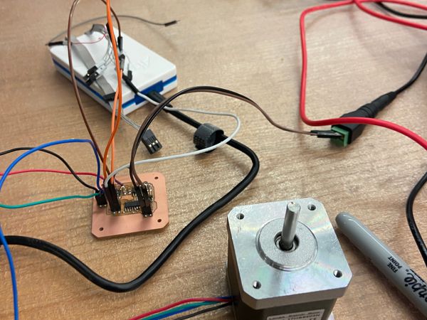
I went back to Anthony and he then recommened that instead I instead use the STSPIN220, and he helped me set up the first one with a Arduino UNO. He then left and I tried setting it up with my dev board
Of course, without Anthony’s golden hands when I connected it to my dev board it didn’t work. Anthony then gave me another one then and again once I connected it to my dev board it stopped working even when I went back to an Arduino. At this point Anthony and I were pretty confused so he busted out the oscillascope, I hadn’t used one before so it was really cool to see how it worked.
We found out that yes, I had indeed fired my third Pollu board. The issue was that I was connecting 5V on my board to the Pollu (which was what I connected on the Arduino UNo) but my board uses 3.3v for it’s logic level. So with a new Pollu board, and Anthony right beside me, we wired it up and it worked!
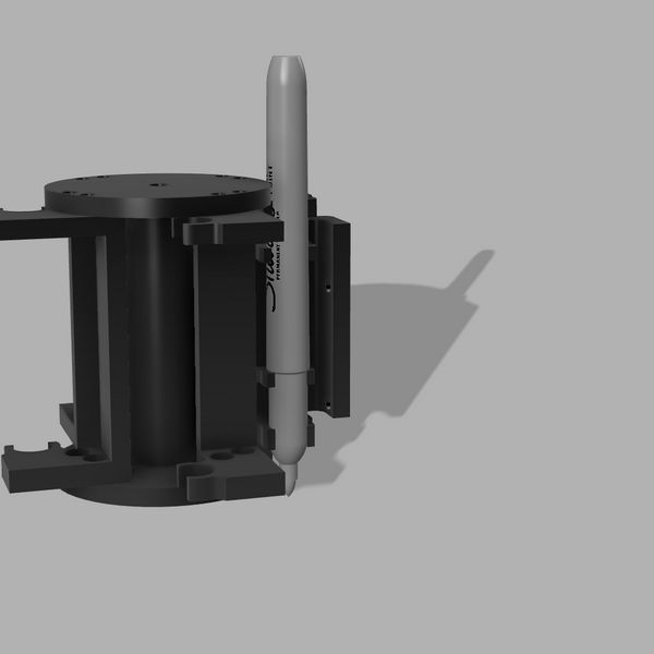
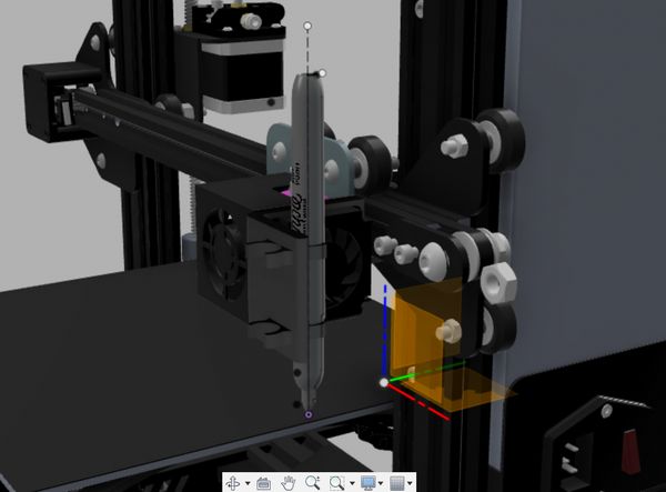
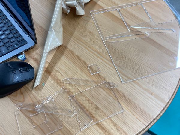
I went back to my printer and then installed all newly 3D printed parts
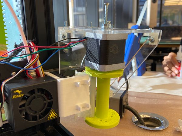
Then I coded a super simple step sequence and tried out the system
Unfortunally, however the stepper just wasn’t powerful enough to force the sharpie onto the flexture. I tried adding extra capacitors and increasing the voltage (I didn’t realise that the steppers were 10V rated and so burned one of them) but to no avail. Unfortunately, I only managed to get the stepper working on the Tuesday of presentations so I was unable to do anything more, however I am doing this for Projx so will be continuing this later and will link to updates then.