11 | Networking and Communications
For this week the assignment was to design, build, and connect wired or wireless node(s). Last week I unfortunately didn’t get my stepper motor controller to work so for this week I decided to tackle the two things at once and rebuild my stepper motor controller along with a dev board and get the devboard to communicate with the motor controller to spin the stepper.
Designing a dev board
For the last couple of weeks I’ve been designing a whole new board for every project with its own USB connector, voltage regulator, and most importantly D11C. Every week, something goes wrong with soldering this and when I plug it into the Atmel-Ice I’m greeted with a list of errors as I debug my circuit. Well this week I decided no longer. I wanted to make a devboard so all my future projects can just consist of designing breakout boards and programming the code not flashing a bootloader, etc.
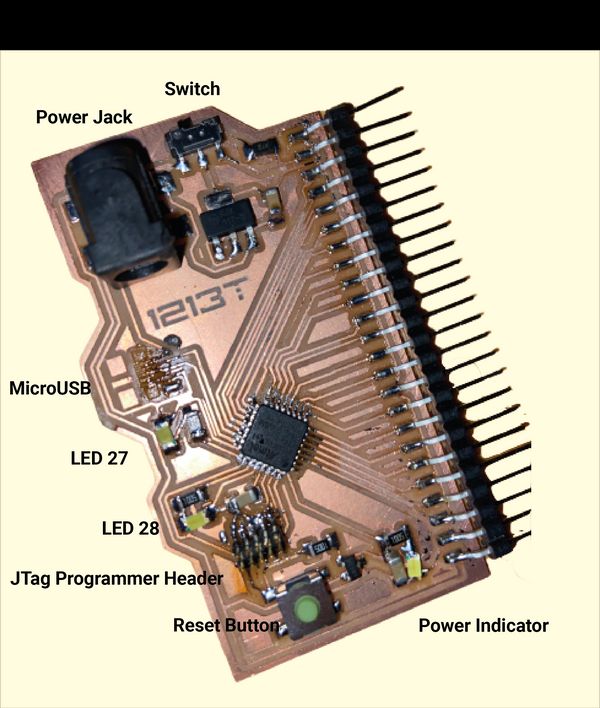
For my dev board I was heavily inspired by Lingdong’s from last year. He uses the SAMD21E which is the chip I wanted to use (due to it’s large amount of pins) and he includes a barrel-jack power connector, power switch, microusb, indicator leds, and reset button. In effect he built his own little Arduino.
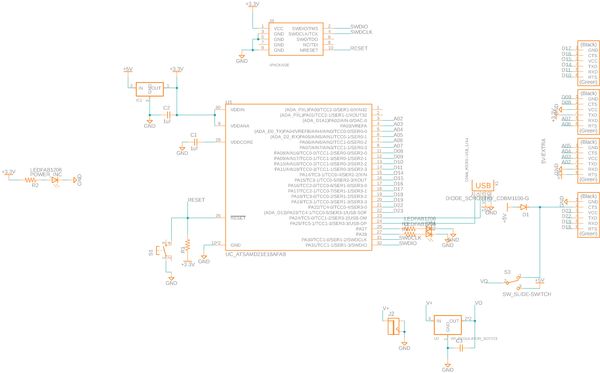
To build mine I decided to approach it in spirals. First I implemented everything in Neil’s example schematic for a SAMD21E board. I had previously done this for my multiplexed LED board so I was able to copy some of the components over.
Breaking out the pins
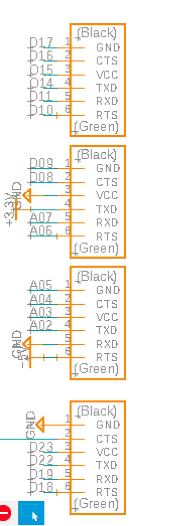
Afterwards, I started adding in the extras. First, I wanted to break out all the pins so I could use them with future breakout boards. For similar reasons to Lingdong I opted to use horizontal pins (called **CONN_06_FTDI-SMD-HEADER) instead of vertical ones so that if I put the board in my pocket it wouldn’t stab me as I walk around. I broke out all the pins on the SAMD21E which weren’t already being used except for 4. PA00 and PA01 are both special oscillator pins designed to be used with a crystal. As I didn’t need to do this and they work as regular analog / digital pins I ignore them I kept PA27 and PA28 to have as one board status LEDs Then I connected them to my FTDI headers. As there were more header pins than SAMD21E I also included ground and 5v / 3.3v pins in some places. My first ordering ended up not being the best but I switched stuff around in the routing stage to make everything work great.
Adding a reset button
When working with Arduino code sometimes things go wrong, you end up in a weird state, or you just need to run everything from the start again. Most Arduino boards contain a reset button which takes care of restarting the microcontroller. I wanted one for my dev board also.
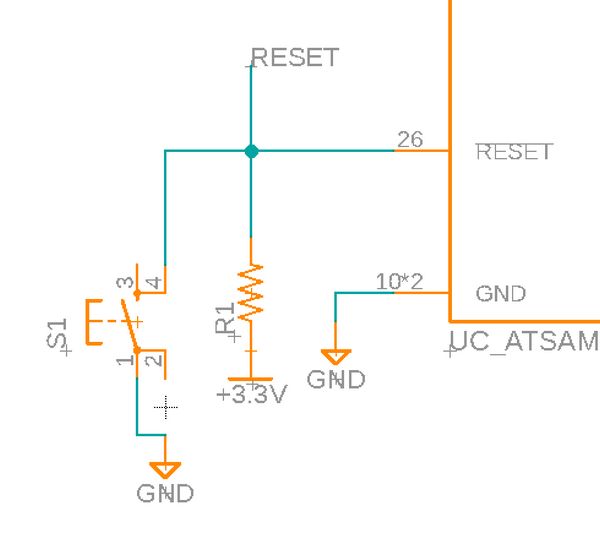
The reset pin works by restarting the microcontroller if it’s ever brought to ground. It’s already being used by the JTag so I connected my extra extra components to the same net. First, I wired the pin to a 100ohm and then to 3.3v. Then I included a button which when pressed will short the whole line to ground.
Power and Status LEDS
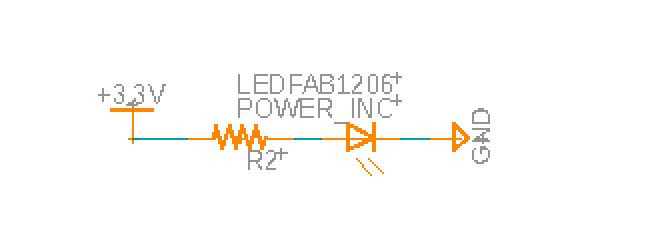
When the microcontroller has power I want an LED to always come on. Then I wanted two other LEDs just for random debugging and as status indicators. For the power LED I wired it directly to 3.3v and ground
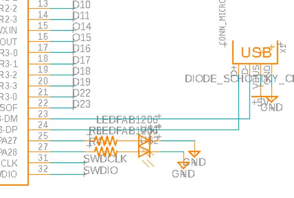
For the status indicators, I wired resistors to PA27 and PA28 which connect to LEDs.
Microusb
For all the previous weeks, I’ve been using the SMD USB which consists of milling out the traces for a USB connector, extending the height with solder and stacks of vinyl, and jiggling it in the USB cable only my computer beeped to say there was a connection. It’s a nightmare. Last week Anthony suggested that I could use a microusb adaptor instead. It has all the same pins as the USB connector so was simple to set up
Barrel Jack Connector
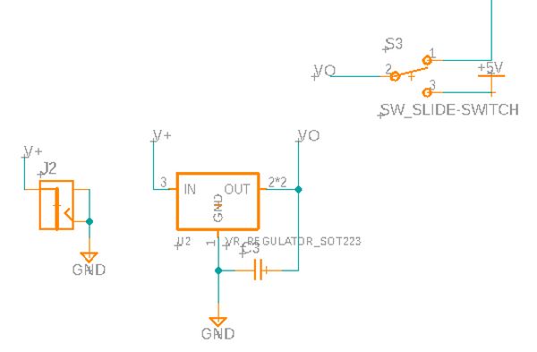
I’m not always going to have my computer around to power the board so I wanted to be able to power it off a barrel jack connector. As this would have 12V I needed to also add a 5V voltage regulator (which connects to the same 5V line as the microusb). Last week, when I did this for my stepper motor board I couldn’t find the right barrel jack to fit the footprint however so this week I went to the architecture shop first and got the wrongly sized connector which I compared against my stepper board to see if it was too big / small. Well, it turns out it was the right size! Last week I was just tired and didn’t rotate the connector. Once rotated it fits.
Finally, I connected a switch to the barrel jack. When on the switch sends the 5V from the regulator to the board and to a pin. When off the 5V only goes to a pin.
Routing the board
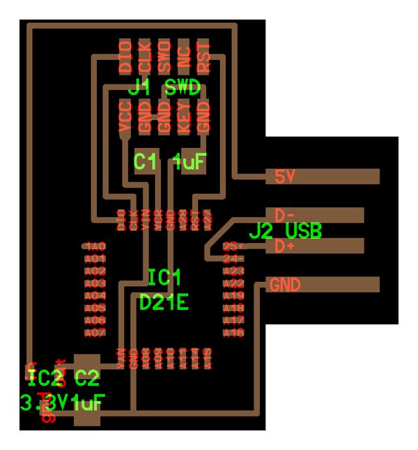
Before I started to route the board I’ll admit I was a little scared. My previous boards didn’t have nearly as many components. I began by placing the SAMD11E in the centre of the board and connecting it to the FTDI headers. At this stage I realised routes were going to cross. Instead of adding 0 ohm resistor I changed the location of some of the pins in the schematic until everything was attached with no crosses.
After this, I placed the other components and routed them all. In the end I was able to get it all to work without any vias or 0 ohm resistors. The trick was to have a ground trace which went on the other side of the FTDI header pads and to route underneath the SAMD11E and button.
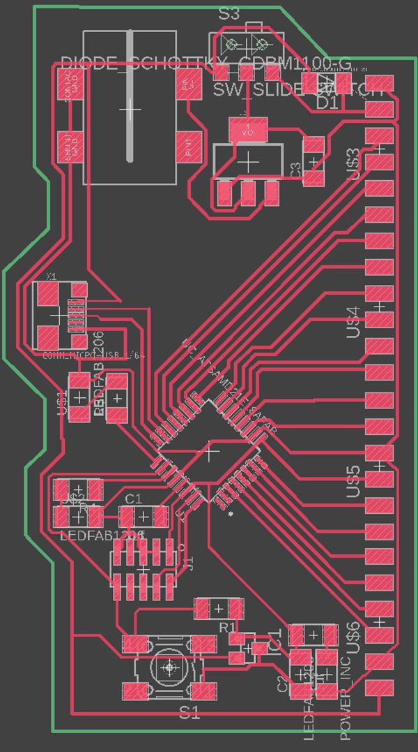
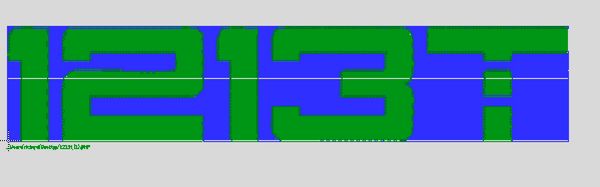
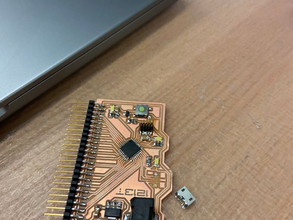
The only thing left was to add a little bit of flair to my board. Last year during 8.01 I was writing some equations on a whiteboard and the number 1213 came up. This looks pretty inconspicuous but my handwriting is atrocious so all the numbers were mashed together and it came out looking like RB which conveniently are my initials. Ever since, I’ve put 1213t on things that I make. However, not just any 1213t, but 1213t written in an obscure font which I found while doing Metropolis’ water jet training. I’ve never been able to find the font again so whenever I want my initials I have to find a saved copy.

I had my initials saved as an SVG so initially wanted to import that. Unfortunately, Eagle had incredible poor support for images.
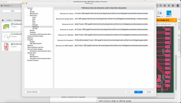
I found a sparkfun guide and followed that. For .svgs it gets you to install a new ULP script. On my mac I couldn’t easily find the location of my ULP script folder, to get yours you can: click your profile in the top right > *Preferences> Electronics> Directoryand then copy the Directory for ULP**.
Next I ran the svg2poly script, clicked on my file, and clicked Ok
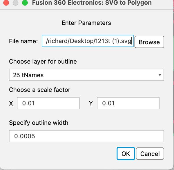
Nothing appeared 😥I fiddled with the scales, and still got nothing. Ok, well the sparkfun guide had two other options so I decided to try those.
The next one was .dxf but I thought that would be similar to .svg and instead I’d use the bitmap.
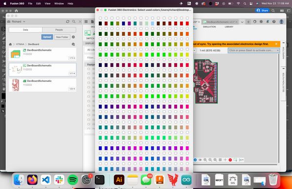
I opened up my .svg in Illustrator and exported it for bitmap. Illustrator will then ask for a colour profile. I tried all of them and only bitmap words. To import the bitmap you run run import-bmp and select your file. When I selected a RGB colour profile it complained that there were too many colours and for greyscale Eagle showed off how old of a program it was by displaying the colour selection window so large that I couldn’t click the ok or cancel button.
When using bitmap mode I was able to select black and white and it imported my image! But, it’s literally composed of individual squares of a specific colour. When importing the image I skimmed the warning prompt but the TL;DR; was that this feature wasn’t intended to make features you’d keep but rather features you’d trace over with the polygon tool.
The only option left to try was using .dxf files. I went back to Illustrator and reexported my svg as a dxf this time. Then I used the run import-dxf command. This creates a popup which asks for you to select a location and specify a scale. The first time I ran this command it showed me nothing, but after messing around with the scale property I eventually got something visible!
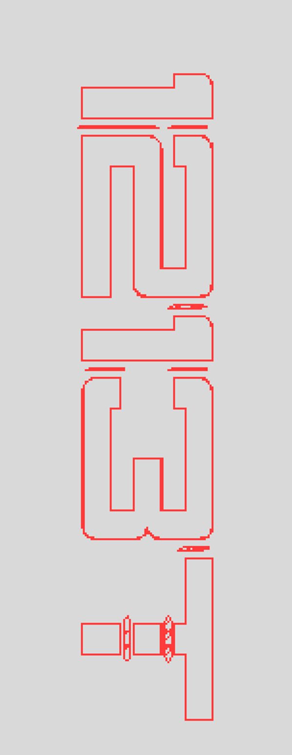
Unfortunately, due to my clearance settings the traces were all too close to each other and Eagle wouldn’t let me move them directly. I had to deform each letter to make it compliant with the dxf rules, move it individually and reassembled at the end. I then filled in the area surrounded by the letter traces using Polygon > Polygon Pour from Outline. It looked pretty awful.
[Routed board]
Then I tested what it would look like in the Othermill.
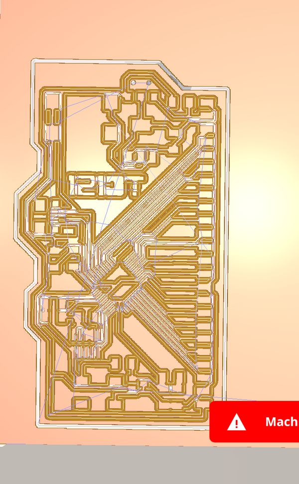
Yep it got no better! To get the lines on the 2 got forever and changing the height but not the width meant it no longer looked like my signature. At this point I was 2 hours in and pretty frustrated. Finally I did what I should of done at the very beginning and started googling. Eventually I realised that the Othermill supports engraving with svgs directly. Not gonna lie, I was a little bit annoyed. Why couldn’t I have realised that 2 hours earlier! See below for how I set this up.
Milling the board
After the disaster that was last week with the OtherMill in Metropolis I was nervous about how things would turn out. As a quick refresher last week I broke the last 1/64” endmill by cutting two deep so that when I looked over the bit was just hovering in the air I tried using the PCB engraving bit but it ripped up my traces.
Metropolis had ordered new 1/64” bit endmills (using the cheaper supplier Anthony told me about :)) but they asked everything to avoid using it unless absolutely necessary. The 1/64” cost around $18 and easily break due to how small it is. The engraving bits cost ~$1 and last much longer as they have a lot more metal due to being tapered. Also, they’re so much faster. Switching from the 1/64” FEM to 0.005” engraving bit reduced my milling time from 39 to 25 minutes.

Before starting I found a guide by Bantman Tool’s (the company OtherMill rebranded to) about how to properly setup the engraving bit.
I measured the thickness of my material with a digital callipers (in the past I had just done this with a ruler) and inserted it under thickness I measured the thickness of the double sided tape (Anthony had also advised doing this last week) I carefully stuck the double sided tape so none of it overlapped (which would cause a height difference)
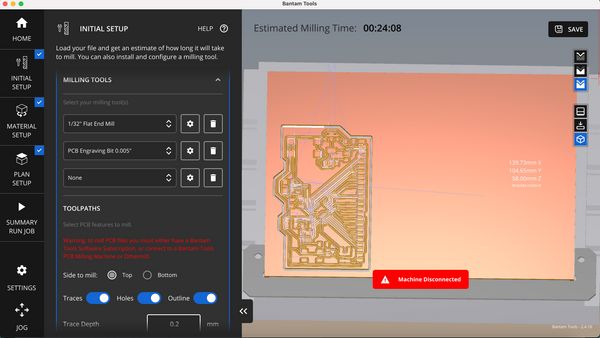
Once everything was set up I added the svg file. With the Bantman tool software this was super easy. Exactly the same as adding a .brd file I clicked Open file, selected my SVG, and then changed the tool it wanted to use to the 0.005” PCB engraving bit. Finally in the Plan setup tab I positioned the text where I wanted it engraved**.
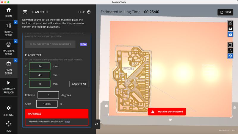
Once setup, I ran the milling job and everything worked great.
Updating the stepper motor controller
With the dev board designed I updated my stepper motor controller. This was super straightforward. I was already using all the pins for the SAMD11C but I needed two to do IC2. So I removed the USB cable and instead added another 2x2 connector header and wired the D+ and D- pins to that. I won’t be able to put a bootloader on the device but flashing it isn’t that bad.
Stuffing the boards
When I got the EDS to stuff the boards I immediately found Anthony to ask him about how to use solder paste. The SAMD21E has sooo pins and I didn’t want to do that by hand .He got me to put on gloves (since the leaded solder can be so small that it gets into your pores) and gave a quick demo. Basically you gently push the syringe so a tiny bit of paste comes out and links all the pins. Then you place your component on top and use a hot air gun to melt the paste into solder. The transformation from the dull grey paste to the shiny solder was particularly cool to see.
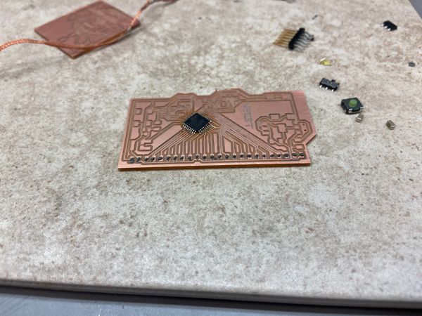
Everything else was straightforward, the only weird thing I had to do was the barrel connectors had holes underneath them (I think there’s a footprint on Eagle which accounts for this) which meant they weren’t flush so I used an exacto knife to remove these.
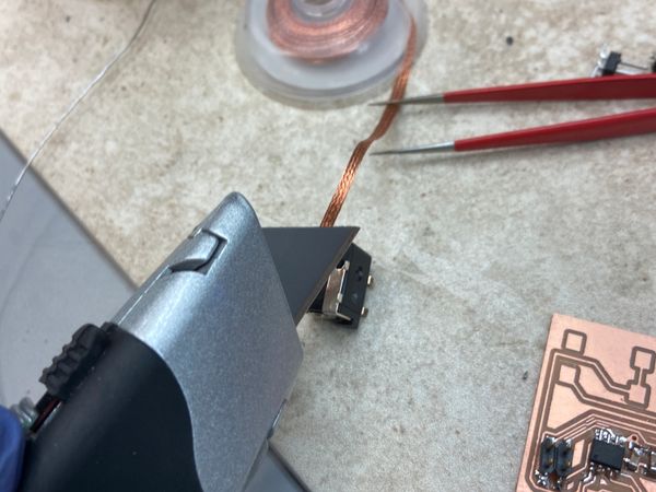
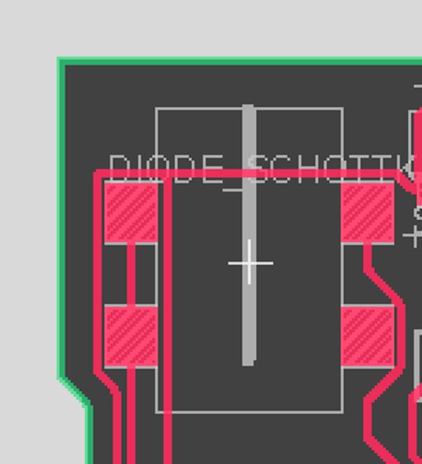
While soldering I realised I made a mistake with my dev board and placed the barrel jack connector the wrong way around. The line through the centre shows the wall of the connector. This meant I had to place it facing into the board.
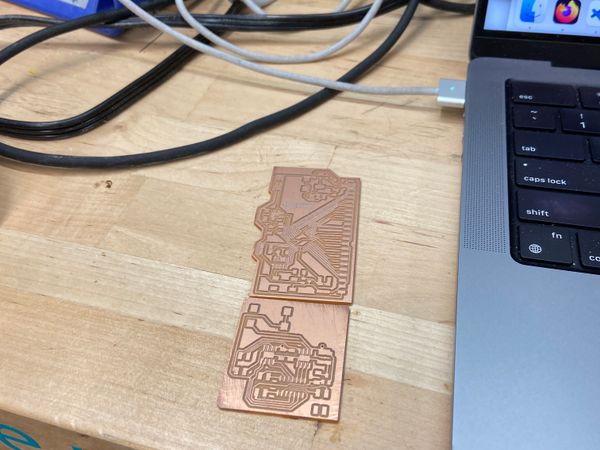
But both boards turned out great
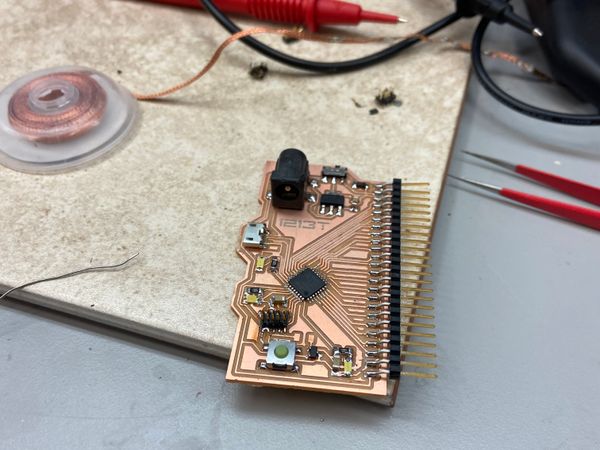
Flashing
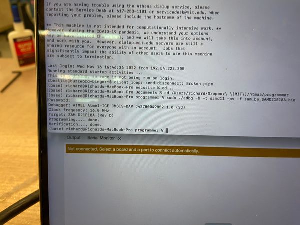
For the first time ever flashing was as easy as plugging the Atmel and the microusb into the board and running the edbg command
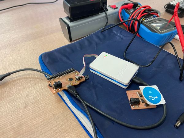
Everything goes awful
After flashing so easily I was super excited and hopefully and just generally everything was sunflowers and rainbows in EDS. Until I noticed that my power LED wasn’t turning on. I was confused with the polarity of the LED so I assume I placed it on wrong. In my rush to resolder them however I pulled too hard on the microusb cable and ripped up the connector
I tried resoldering but it only made things worse and before I knew it all the connectors had been broken and the microusb part of the board was unusable.
However, I thought I could still flash it with the programmer. I resoldered all the LEDs and then plugged in the barrel connector but nothing showed up. When I used the voltmeter I kept getting wild fluctuating readings. It was late and in my rush to get it done I made a stupid decision. I thought the barrel connector might not be connected right so I used the jumper cable to connect the two pins on the same side one was 5v the other I thought wasn’t connected to anything – but it was, it definitely was. Once I connected them, smoke appeared and my SAMD21E glowed orange as a bubble and hole appeared 😱. At this point EDS was closing so I had to leave but I’ll be back once it opens after Thanksgiving to finish everything.
Issues for Rev 2
- Didn’t breakoff 12V
- Barrel Connector & micro usb should be there own breakout boards
- This way if they break it’s much easier to fix them.
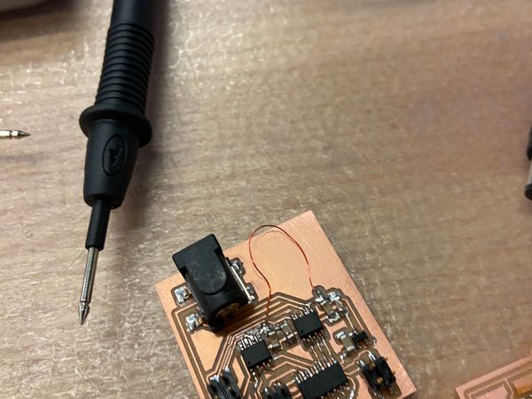
Communicating
Eventually I got my board to work and then milled a second one. I found out what the I2C pins where, connected these together and put the example primary and secondary device code from the Arduino wire library on them. And it worked!
Receiving code
#include <Wire.h>

void setup(){
  Wire.begin(8);
  Wire.onReceive(receiveEvent);
  Serial.begin(9600);
}

void loop() {
  delay(100);
}

void receiveEvent(int howMany){
  while(1 < Wire.available()){
    char c = Wire.read();
    Serial.print(c);
  }
  int x = Wire.read();
  Serial.println(x);
}
Sending code
#include <Wire.h>

void setup(){
  Wire.begin(2);                // join i2c bus with address #2
  Wire.onRequest(requestEvent); // register event
}

void loop(){
  delay(100);
}

// function that executes whenever data is requested by master
// this function is registered as an event, see setup()
void requestEvent(){
  Wire.write("hello "); // respond with message of 6 bytes
                       // as expected by master
}
Unfortunally, this occured after the week ended so I didn’t have enough time to do anything super cool, instead I had networking in my final project which you can read about on its page