13 | Machine Building
This week was a fun one. There was no individual project instead the entire section worked together to build a drawing robot. Of course, with such a large project in such a short time we had to break into sub teams. On a high level there were three teams: software, firmware and hardware. I worked on the end effector for the hardware team but you can read about the other teams at our detailed write up
End Effector
For my final project I need to pick up and use sharpies to colour in 3D prints. This is similar to the requirement for this week to have a pen / sharpie / some other drawing instruments that can be moved up and down to draw on the paper. I decided to work on this as I hope I can repurpose it.
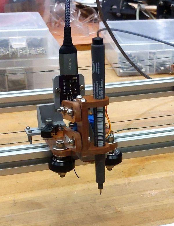
For the end effector we based it off the UrumbotXY drawing machine end effector. It has a pen holder connected to two arms. One arm can be rotated by a servo while the other freely rotates. Due to this for small rotations the holder moves vertically allowing the pen to be put up and down.
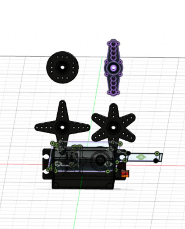
As we had changed some of the Urumbot’s sizes and used different thicknesses for materials we first measured all our new parts and decided on which servo to use. Anthony had Mini servos and standard size servos. We decided on using the MG996Rs to be sure we’d have enough force to engage the pen.
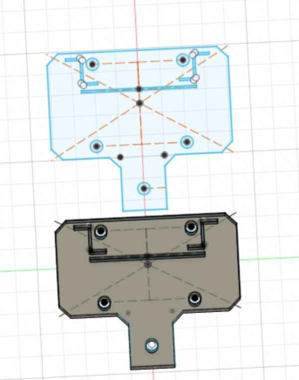
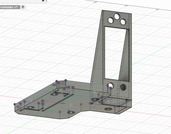
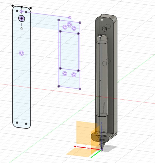
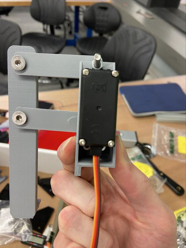
To design the servo holder we first imported the model of our drawing machine’s effector holder and adjusted the thickness to match the acrylic we had ended up laser cutting.
Then we projected this component into a new sketch to ensure we had the right dimensions for the servo holder. We cut out a section for the servo to be pressed into and also holes for the screws. Unfortunately we placed the hole for the metal rod too close to the screw holes such that the heads of the screws bumped into it making it unusable.
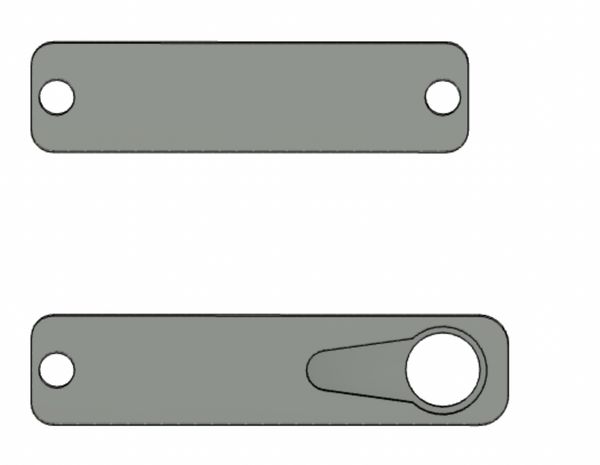
Next we designed the arms. The freely rotating arm was simple but for the arm that was to be attached to the servo we needed a model for the servo horn. Thankfully we found a model of the servo on GrabCab and imported that.
We projected the two prong horn into a new sketch, removed one of the horns and scaled it down. Then we sketched an arm around it.
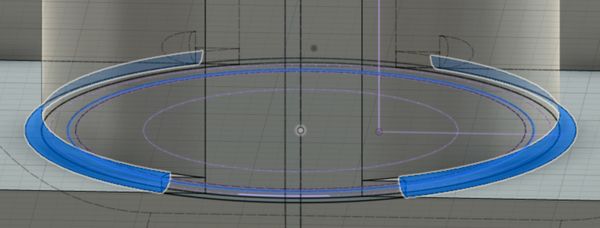
Finally for the sharpie holder. We decided to have something where the sharpie could sit inside to make it easy to switch the sharpie out. We first went back to Grab found but this time for a sharpie model. Then we sketched and extruded the holder for the sharpie which we combined with the sharpie model to get the right gap for the sharpie to sit in.
Finally we extruded a wall around the sharpie to hold it in place. To give this a bit more strength we rounded the sides into the base by extruding out an offset and cutting into this using pipes.
Then it was also ready to go to the 3D printer. Unfortunately, we printed it with draft settings the first time which meant all the parts snapped when a bit of pressure was applied but we printed them again this time with 20% triangle infill and it worked great.
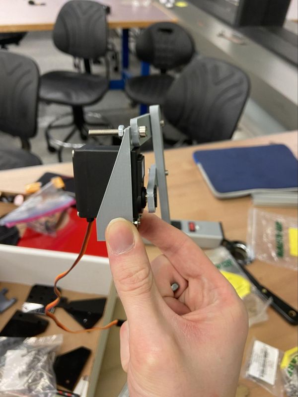
Once they were all ready, we attached all the parts with M3 and M5 nuts and attached it to the drawing machine.
The Drawing Machine
There were a lot of steps between attaching the end effector and getting it to draw (and at least a dozen of them involved hot glue) but in the end it worked.
First we drew Kirby to test out our horitzontal line feature
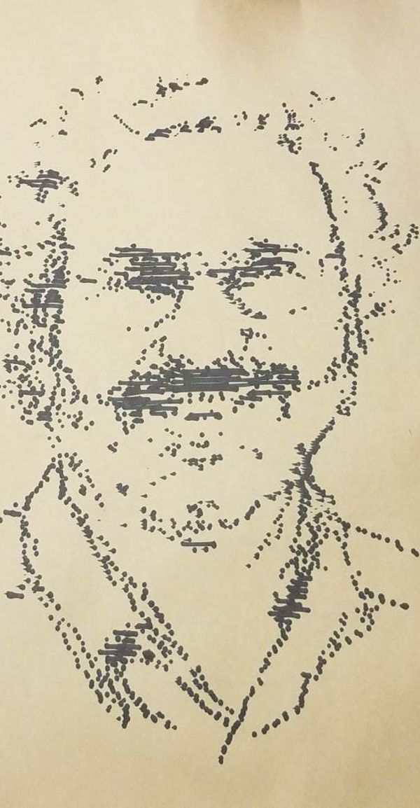
And then to test out faster drawing with dots with did Neil’s face
which came out great