06 | Embeded Programming
This week much more relaxed that last week which was great as it gave me time to look more into stuff I didn’t get time for in previous weeks.
The idea
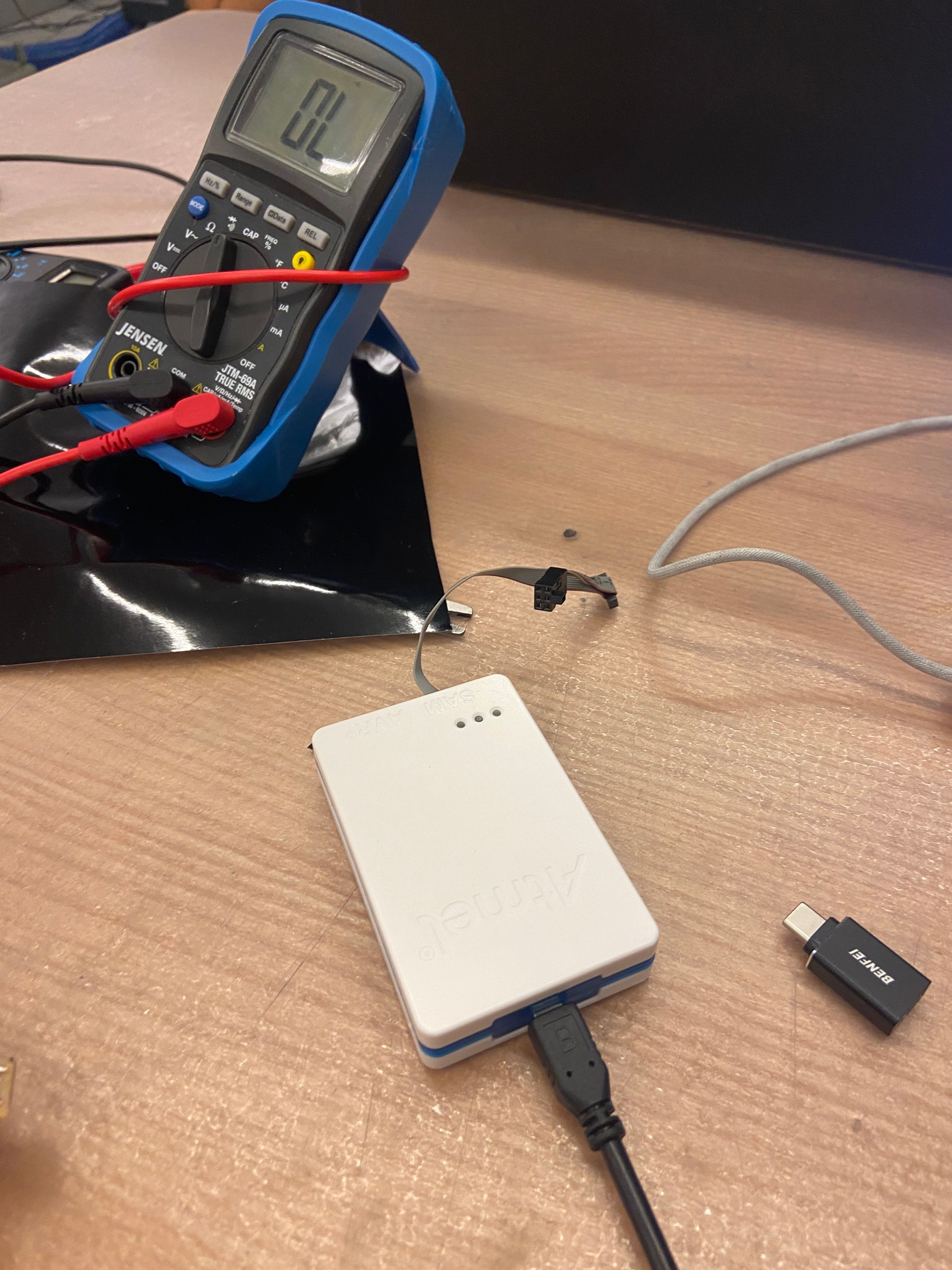
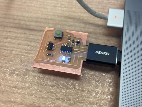
My first task was to program my echo-hello world from 2 weeks ago. Unlike during week 3 flashing the bootloader was super easy. I had EDGB set up on my mac already (thanks to Jake's guide. I unfortunally had to use the Atmel in EDS rarther than my own bootloader board since I haven't been able to get it work with my mac.I connected the programming pins of my board to the programmer and flashed the Arduino bootloader. Yay :)
To actually be able to code the board with the Arduino IDE there was a couple of steps. I again followed one of Jake’s guides this time the FAB Arduino SAM Guide. The main steps were:
- Adding a new board manager URL
- Switching my board in Arduino to the Fab SAM core for Arduino
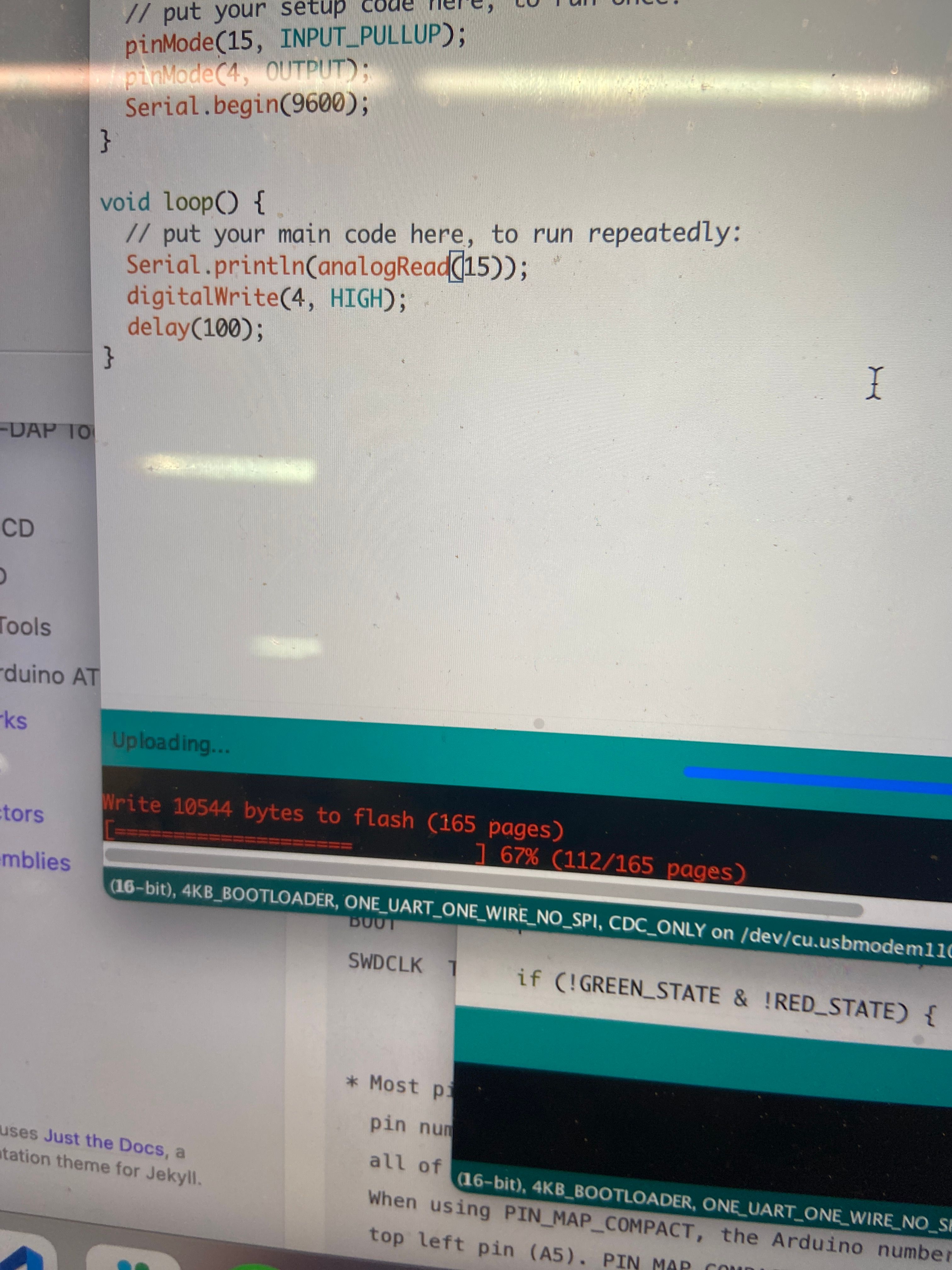
Once I got the Arduino IDE talking to my board I needed to figure out which pin my LED was on and which pin the Button was on. The physical pins on my board don’t neccesary map to pin numbers Arduino knows about so I had to compare my board with a Pin Mapping Table Jake nicely provides
Once I figured out which pins my button and led used. I coded a simple sketch which turned the LED off whenever the button was clicked. After uploading the code to my board, the LED turned on! but when I clicked the button nothing happened.
It turned out that I didn’t pay enough attention to my microcontroller’s datasheet and so the pin that I had connected the button to was an oscillator which is why I couldn’t read anything. I then had to scrape off the connection to that pin and solder a piece of magnetic wire between a another of my microntroller’s pins and the trace to the button
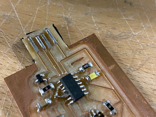
This was a little dodgy, but it worked! Clicking the button turned off the LED
Making an LED matrix
I wanted to try design another board and test my ability in Eagle to learn a lot more. Alayah from the Architecture section had been talking about multiplexing LEDs and I decided to try make a board that did that.
What is LED multiplexing
The SAMD21E microcontroller that I decided to use for my board only has I think 26 pins which can be used to control outputs. If I did what I did with my echo-hello world and wire one pin to one LED this would let me only control 26 LEDs indepdently. However, there’s lots of applications where you need to drive a lot more LEDs, in comes multiplexing. Multiplexing allows you to control n^2 LEDS with 2n pins. The LEDs are arranged into rows and columns. By outputing LOW and HIGH to different columns and rows you can selectively turn on individual LEDs. If you turn on and off LEDs fast enough you can take advantage of some persistence of vision effects to make it look like a whole group of LEDs are on at once.
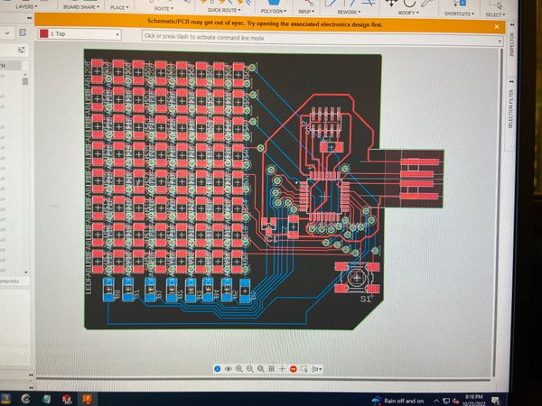
Designing my board
I decided I wanted to make a 8x8 LED matrix. This was definetely a mistake, I should of started with a smaller size matrix. The learning would of been the same but I’d been able to iterate faster and correct my mistakes. I unfortunally I didn’t do this and my mistakes killed me.
Firstly I decided to use the SAMD21E since it has the required pins and speed to run my matrix. I based my circuit off the SAMD21E hello-world board on the HTMAA site.
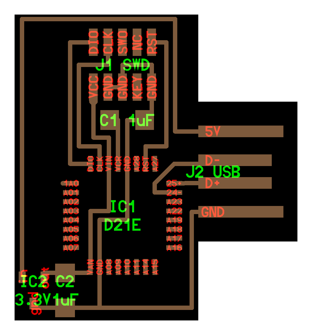
The first thing I did was to define my rules in DRC. I vividly remembered two weeks having to painstakingly select all my traces to change them to the correct width. I didn’t want this to happen again (Future Richard here - Wow, what wishful thinking)
I then added 64 LEDs and started trying to position them into a square. This got tedious. Fast. So google told me that I could rectangular pattern them using an Eagle script. This was painful. Instead of selecting the components I had to make sure that each LED had an incrementing name, type in the base prefix of that name, and then guess at which spacings would be best. Of couse, the day after I had finished doing this I went into EDS and Anthony was super excited because Fusion had just been updated to natively support rectangular patterns. :(
Once everything was positioned on the board, I started adding wires for the rows and columns. One of the other reasons I decided to do multiplexing is that I knew I wasn’t going to be able to route everything with only one layer and I wanted to learn how to make double-sided circuit boards with vias. I think I was a little too eager on this front, when Anthony saw my board he wished me luck since it’s going to take a while to rivet and solder. Vias are not fun. I will be spending more effort trying to avoid them in the future.
Then I began routing, fusion has a nice feature where you start routing on one layer and then press the middle mouse button to switch to a via placer, and once that via is placed Eagle switches to the other layer.
Once I finished my circuit board, I showed it to Anthony who pointed out a couple of errors
- I had intially forgot to add a button and resistors for the LEDs so I had go back and add all of those.
- My first traces where all the correct width (12) however at some point they switched back to 6 so I had to change all of these:
- A quick way of doing this is to only view the layer with traces (/display none 1), then select all the traces, type ("/change width 12"), and right-click -> "Apply to group"
- The size of my via's was incorrect. This was a big pain, thankfully all the vias are in a specific layer so I did the trick above (expect with layer 18) and changed all their sizes easily. Unfortunally, this made lots of components overlap so I had to go back over everything and increase the spacing between my LEDS. I wish Eagle was parametric like Fusion.
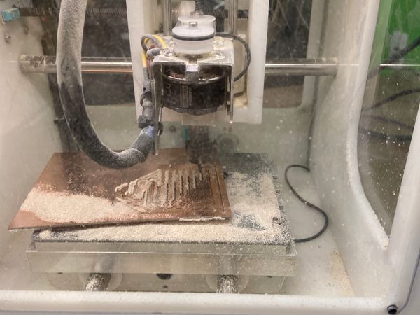
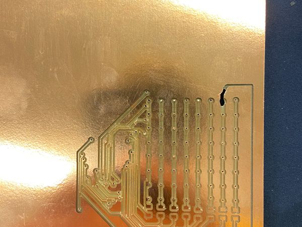
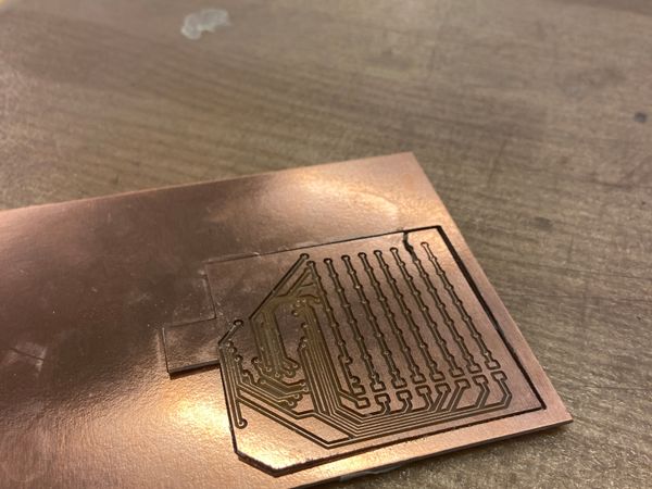
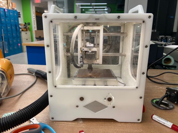
Milling my board
This look an unresonably long time: over 2 hours. The top layer alone took one hour, this was partly my fault in previous weeks I had left a lot of copper around the USB connectors which I had to scrape off. However by changing the trace clearance setting you can get the Mill to do this for you. I changed my trace clearance to 3mm, however you can’t selectively apply it only to the usb so it added about 15mins to the job.
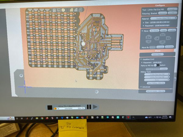
I mistakening set the tool as 1/32in Flat End Mill so my traces all came out a little rough, which I needed to sand down
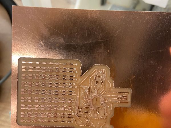
Once the top layer was done, I flipped the board over and aligned it with the other side of the bracket that had been placed in the Othermill. Then I started the bottom layer. This was going great, until it was time to cut out the outline of the board. I hadn’t taped down the board enough so I heard a loud clanging sound and saw my board lifting up. Thankfully, I was right beside the OtherMill and stopped it quickly but I lost 2 LEDs :(