How can one achieve drawing with music and visually capture a fleeting moment?
Is it this?
Or maybe this?
After searching for inspiration and iterating on a few ideas, I settled on the following something most similar to the SoundWave example above: use a mic for audio input, then parse the analog signal to sequentially extract the min and max values in a fixed number of samples. Scale these values as valid inputs to control the start and end points of movement for a stepper motor. The motor mechanics does the following in repeat: 1) lift the servo controling the pen position, 2) increment the paper forward using a stepper motor. 3) move stepper motor 1) to start point 4) set the pen down. 5) move stepper motor 2 to end point.
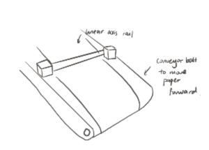
For the design, I thought about using CoreXY but wanted to try implemeting something different. I initially had a conveyor belt idea where the belt and a linear axis creates the two dimesional plane to draw on. Anthony suggested using a wheel to move the paper foward vis friction. I liked this idea as it makes the machine design a lot more compact.
Here is the materials list. All parts can be manufactured at or were available at EDS.
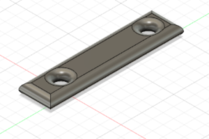
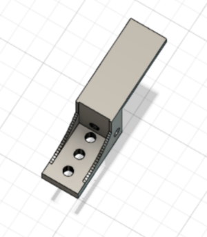
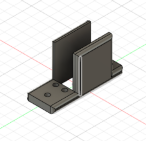
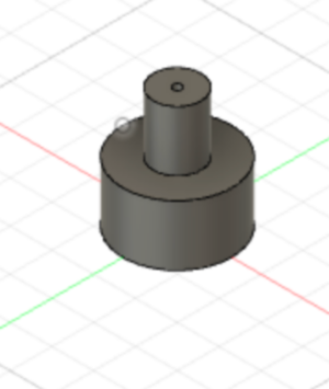
First, I created the hardware of the project using the resources from Quentin's Beehive Axis Linear Rails and inspired by EECS section's Machine Week Project: the CoreXY drawing machine. I CADed and printed the components in PLA for the Servo Motor Contraption for lowering and lifting the pen. Here are images what what they look like, I had to try 2 designs of the servo holder as the first one was not structurally sound. I also CADed a rubber wheel large enough to barely touch the table surface from where it's secured, so it can increment the paper forward via friction. The wheel was printed in TPU with a low infill percentage (around 10%) for maximal flexibility.

Then, I assembled everything, being creative with the attachments when the appropriately sized nuts and bolt were not available.
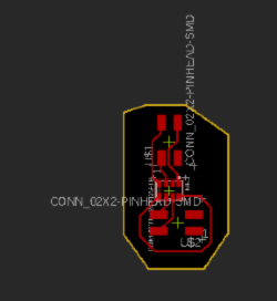
Next, I moved to the digital fabrication component of the project, where I made use of the products from input/output devices weeks and the skills from the embedded programming week. In week 8 (Input Devices), I created a PCB board that reads mic input. In week 10 (Output Devices), I created a breakout board in order to make use of all the pins on the SAMD21 Microcontroller.
To wire the stepper motor, I had to first figure out which pairs of wires went together in the stepper motor. Then, I connected the corresponding pairs to each set of MS pins. I connected VIO to 3V3, VM to 5V, and ground. The other side of the stepper motor driver had various control options. I only used the STEP and DIRECT option to increment the stepper motor and control the direction. Finally, I made sure to connect the enable pin (EN) to ground.
For the servo motor, there are three wire connections. The ground, the 3V3, and the PWM. Servo motors differ from stepper motors in that it has a sense of its location. Namely, I can define the angles that it moves to. So I have a setting for lifting the pen up and moving the pen down.
After making the connections, I tested that each component was working properly.
Servo
Stepper incrementing the wheel
Stepper moving the pen
Then, I moved to implementing serial communication as the mic and motors were controlled by different microcontrollers. On the software side, I wrote code for the mic to take 50 samples and extract the min and max values and scale to appropriate range of 1000 to 3500 that will respectively serve as the start and end points of lines drawn. I tried to set up Serial3 transmit from the mic to Serial 1 read for the motor. However, after many hours of debugging with Junhong and Anthony, we knew that the mic was reading and processing correct inputs by checking the serial output with an FTDI cable. However, the mic is either receiving -1 or 0 only. I tried to resolve this by making a breakout board with just the mic to be plugged into the same microcontroller, but alas, no success. To deal with this, I generated random values for the machine to draw and plan to further debug over IAP.
Next Steps:
Key Takeaways:
Weeks Covered:
Here's the final project in action! :)