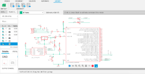
This week, I learned to make a echo hello-world board and add an LED & switch to it. Following the helpful video tutorial here, I familiarized myself with the Eagle interface in Fusion 360. Then, I downloaded the fab library containing all the electrical components I would need, including a SAMD21 microcontroller, a USB port, a CONN_05X2_ARM_DEBUG, a switch, an LED, 2 10kOhm resisters, 4 10uF capacitors. I also needed to use the 3V3 and 5V power supply, ground (GND) from the supply1 library built into Eagle.
Eagle is much like Rhino, with a command line where I type in the operation I want to perform. I used "add" to grab these components from the libraries. The command "move" was helpful as I could drag the center of a component to locate them to a different spot, right clicking while moving also rotates the component. A helpful trick is to group components and them perform "move group". Finally, I used "net" to connect appropriate spots that will specify the connections when I perform the wiring. A helpful tip is to use "name" to label the wires so that an automatic prompt comes up to connect wires with the same name, without physically drawing the wires. Here is the final diagram.
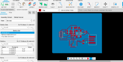
Next, I switch over to the wiring tab to create the schematic actually used for milling. All the components and nets from the previous step are here, I just needed to use the move commands to arrange the components and wire them. This was like a game of tetris, I found it quite fun (and a bit frustrating) to find an optimal position such that all the wires can be connected without overlaps. I found two tricks very helpful.
1) Create a layer for ground (bottom layer of the board). Instead of connecting all the GND ports to each other, we can simply connect it to this bottom layer via a "via" :).
2) For situations where overlap is unavoidable, we can add a 0Ohm resister which essentially adds a layer above the board to connect connect components. Each resister can then have at most two wires running underneath it for making other connections.
Here is the finished schematic diagram. Though not the prettiest or most compact, I am quite proud of it!
Here is the finished board! Although I had vias to make the bottom plane the ground, I accidentally milled on a one-sided board. To remedy that, I threaded a wire through the vias to connect them, being careful not to have the wire touch any other traces.
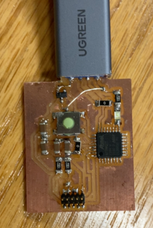
Finally, I uploaded some code to the board and the LED blinks.