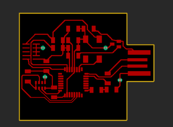
This week for input devices, I decided to explore sound inputs for my final project and wanted to use the mic (hello.CMM-4030D-261-I2S-TR.t1614). I first edited my board from two weeks ago to include this component. Following the SAMD11 manual, I found out that I should connect SD to PA07, SCK to PA10, WS to PA11, CHIPEN and L/R to the power supply, from the mic to the microcontroller respectively. Although it was a relatively easy edit from my previous board, I had techinical trouble working with Eagle (multiple fusion crashes before saving :,() and inserting vias. Additionally, due to the wiring of the mic, I had to add 3 0Ohm jumper resisters. But I enjoyed the learning experience and am more confident with my PCB design skills now. Here is the final board schematic.
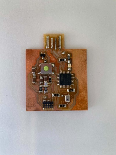
Soldering the mic was a bit tricky and Alec showed me how to use flux, soldering paste, and the hot air gun to secure a joint. Here is the finished board.
Unfortunately, there is a short in the board that I couldn't figure out at first. The TA gave me the tip of using the multimeter as I solder to ensure that each new component I add does not short the circuit. After some tinkering with Anthony, he pointed out that the mic might have been on backwards, and it indeed was! After using the hot air gun to remove and resolder the mic, the board was successfully programmed.