# Hardware
> To build the base of our drawing machine, we referenced Jake's [coreXY system](https://gitlab.cba.mit.edu/neilg/urumbu/-/tree/master/UrumbotXY). The frame was constructed using 20mm width x 60 mm depth aluminum extrusion. The extrusions were cut using a horizontal bandsaw to approximately 32.5 inches in length (horizontal bandsaw on the right, from Csail lab).
> In tandem, we 3D printed the capstan motor and capstan pulley (again, using the fusion files provided by Jake's website) and laser cut acrylic to produce different components, including the pulley mount, motor mount, bearing plates, and feet. Ultimately, we recreated the bearing plates so that it was compatible with our 20 x 60 extrusion constraint and instead used a wooden base.
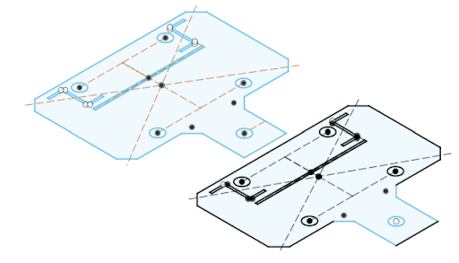
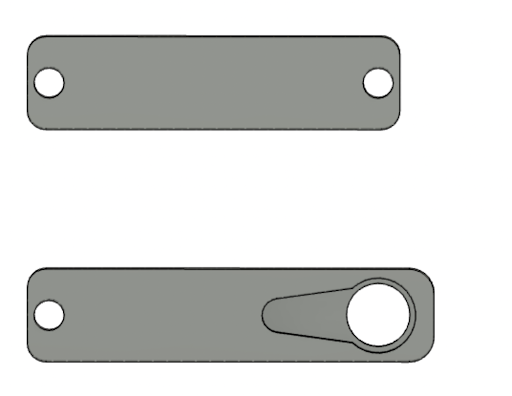
> The modified bearing plates designed on the fusion software:
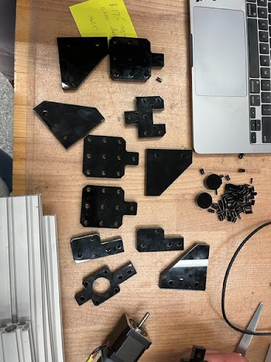
> From left to right: 1) Initial laser cutted parts, 2) corner bearings, 3) prototyped bearing plate using wood prior to using an acrylic
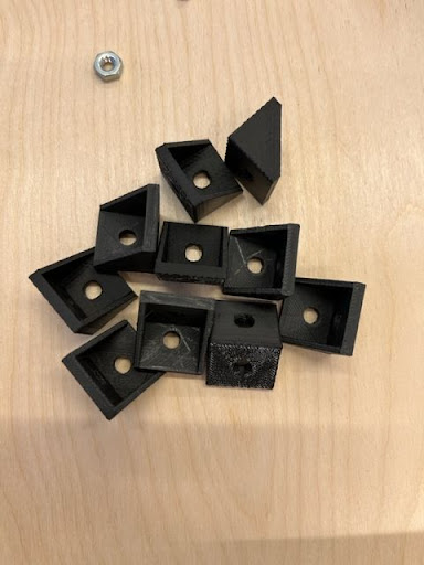
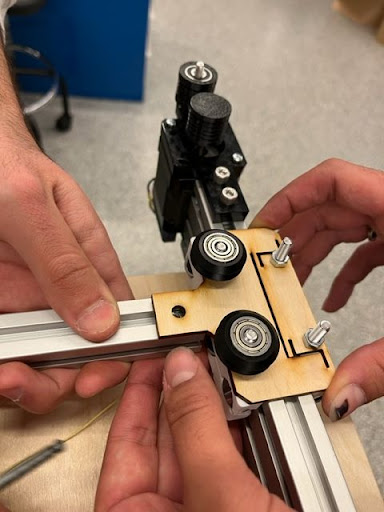
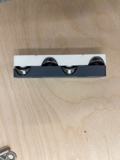
> Initially, we wanted to use a pulley system to enable the machine's XY axial movement, but due to the lack of supplies, we found an alternative approach: [Clank style axis](https://clank.tools/build/composable/). We encountered a few challenges with 3D printing this part because of the malfunctioning of the 3D Prusa printer and the lower manufacturing resolution power of the Sindoh printer. In the end, we filed some inner compartments of these parts to allow easy fitting with the bearings. Consecutively, we mounted the bearing plates to the frame.
> We used a total of 3 pairs of clank style axis:
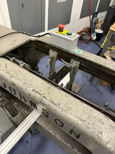
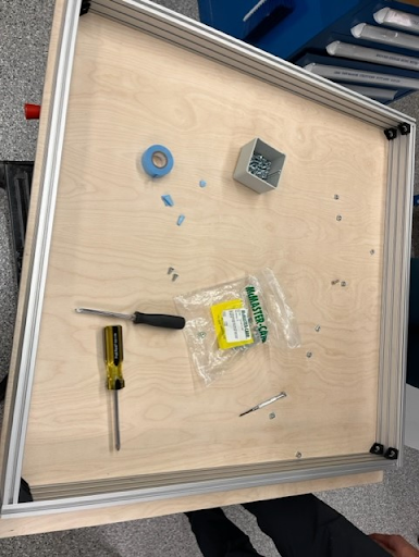
> The base frames were later constructed in the lab. We drilled the wood (3 holes on each side) so the aluminum frames can be screwed to the base. The motor and pulley corners were put together referencing Jake's UrumbotXY machine.
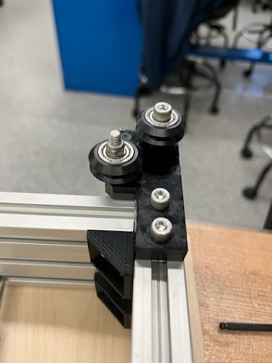
> When assembling the center beam of the frame with the bearings and plates, we noticed that there was a lot more friction compared to the side beams. It appeared that not all of the bearings were rotating at once when the piece was slid along the beam. We originally thought it was because the parts holding the bearings had not been sanded down enough. However, interestingly, when the bearings and plate were moved to one of the side beams, the part slid much more smoothly. We determined that it was an issue with the center beam itself, possibly due to warping. This problem ended up being negligible though, because the part was able to slide sufficiently smoothly for the motors to move it easily.
> At this point, we didn't yet have the end effector or the motors programmed. However, for proof of concept for the frame and setups, we attached the strings onto the machine frame following the CoreXY arrangement. We were able to move the center beam and part by manually rotating the motor end-caps.
## *End Effector*:
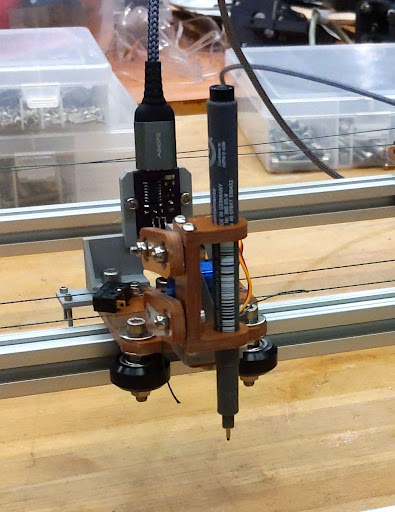
> For the end effector we based it off the [UrumbotXY](https://gitlab.cba.mit.edu/neilg/urumbu/-/tree/master/UrumbotXY) drawing machine end effector. It has a pen holder connected to two arms. One arm can be rotated by a servo while the other freely rotates. Due to this for small rotations the holder moves vertically allowing the pen to be put up and down.
> As we had changed some of the Urumbot's sizes and used different thicknesses for materials we first measured all our new parts and decided on which servo to use. Anthony had Mini servos and standard size servos. We decided on using the **MG996Rs** to be sure we'd have enough force to engage the pen.
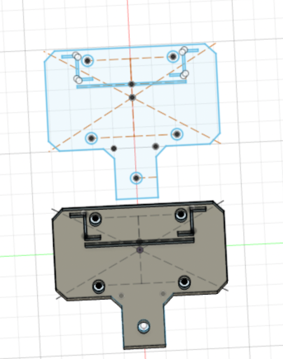
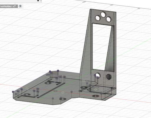
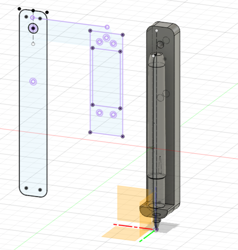
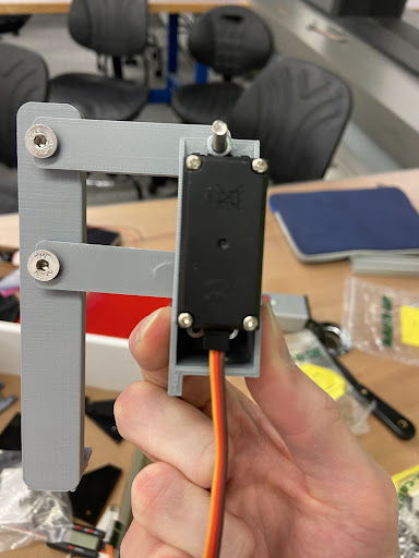
> To design the servo holder we first imported the model of our drawing machine's effector holder and adjusted the thickness to match the acrylic we had ended up laser cutting.
> Then we projected this component into a new sketch to ensure we had the right dimensions for the servo holder. We cut out a section for the servo to be pressed into and also holes for the screws. Unfortunately we placed the hole for the metal rod too close to the screw holes such that the heads of the screws bumped into it making it unusable.
> Next we designed the arms. The freely rotating arm was simple but for the arm that was to be attached to the servo we needed a model for the servo horn. Thankfully we found a model of the servo on [GrabCab](https://grabcad.com/library/servo-motor-mg996r-1) and imported that.
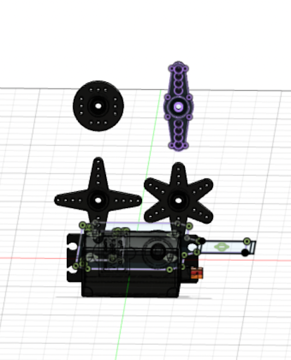
> We projected the two prong horn into a new sketch, removed one of the horns and scaled it down. Then we sketched an arm around it.
> Finally for the sharpie holder. We decided to have something where the sharpie could sit inside to make it easy to switch the sharpie out. We first went back to Grab found but this time for a [sharpie model](https://grabcad.com/library/sharpie-fine-point-2). Then we sketched and extruded the holder for the sharpie which we combined with the sharpie model to get the right gap for the sharpie to sit in.
> Finally we extruded a wall around the sharpie to hold it in place. To give this a bit more strength we rounded the sides into the base by extruding out an offset and cutting into this using pipes.
> Then it was also ready to go to the 3D printer. Unfortunately, we printed it with draft settings the first time which meant all the parts snapped when a bit of pressure was applied but we printed them again this time with 20% triangle infill and it worked great.
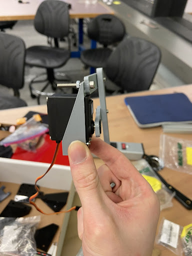
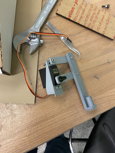
> Once they were all ready, we attached all the parts with M3 and M5 nuts and attached it to the drawing machine.
# Software

EECS DrawBot User Interface
## Python Image Slicer
A Python Flask web-server accepts API calls from the UI interface, and translates the input image into machine commands,
which are returned to the drawing bot. There are three strategies used: grid dotted, contour, and horizontal. Many
parameters are exposed which control the slicing results, such as: DPI, tool diameter, number of shades, and tonemap
threshold.
The api returns the processed image and the toolpath instructions for the drawing.
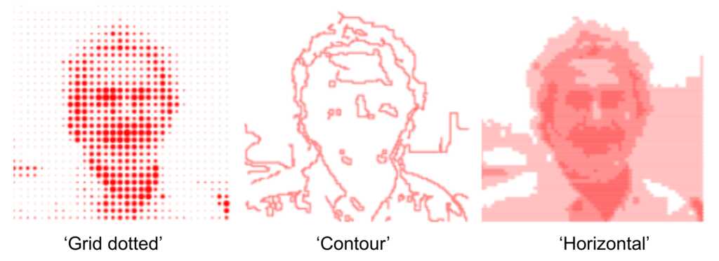
Three modes of image slicing: grid dotted, contour, and horizontal.
## Web Interaction with DrawBot
For the software, we used much of Jake and Quentin's [modular-things](https://github.com/modular-things/modular-things) to interface with the drawing bot.
- First, the UI accepts any input image, along with all the input parameters, and sends it to the web-server.
- Then, the UI displays the preprocessed image which can be modified by updating the parameters to edit the drawn object.
- Then, the UI takes the machine commands, which are then sent to the motors to control the drawing procedure.
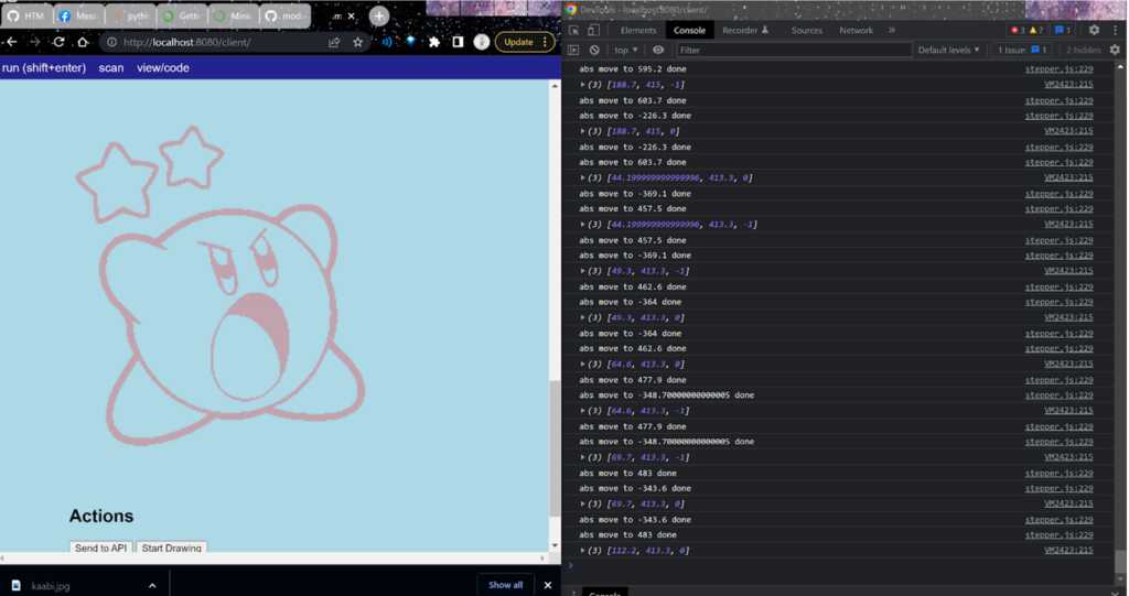
Javascript-based web interface interacting with DrawBot hardware with each motor step outputted in the console.
# Firmware
<!-- > *Note: All firmware related steps go here and put images and videos under `./assets/hardware`* -->
> The firmware team's job was to write up the code that would tie software outputs to hardware instructions. In preparation for this week, the TAs compiled a backend structure called "modular-things" (https://github.com/modular-things/modular-things). Their system allowed us to modularize every aspect of the machine-- every spinning component had its own name and variable in the code. Their examples directory has now been updated with more related use cases, but we had used the [Potentiometer file](https://github.com/modular-things/modular-things/blob/main/js/examples/potentiometerMachine.js)(aka an etch-a-sketch) for reference. There are two main components in the code:
* Calling createSynchronizer with all your project's motors, so you don't have to individually manage movement for each motor in the corexy setup.
* Running asynchronous calls on reading and changing state (in our case, coordinate location) of the stepper.
> It's interesting to contrast the modular-things example code with that of Urumbu's [corexy implementation](https://gitlab.cba.mit.edu/neilg/urumbu/-/blob/master/UrumbotXY-Fall2022/code/urumbu_gcode.py), as ours is much smaller thanks to the abstractions of networking and synchronizing done by modular-things.
> Using the modular-things as a starting point, we were presented with a sort of javascript IDE:

> Motors and servos connected via USB show up in the List of Things panel. You can name the motors/servos in this panel and under their names there is a list of the function that can be used with each device.
> To start, we flashed a bootloader and uploaded arduino code onto the USB/SAMD21 boards we connected to our two motors and servo. The arduino code was pulled from the modular-things github; it allows the motors to be found and translates the higher level javascript commands to a language the SAMD21 can understand. We hooked up both motors and, using the corexy function "createSynchronizer([amotor, bmotor])", we were able to tie the motors together, such that a single location command would cause them both to move. This was necessary because of the structure of the corexy system:
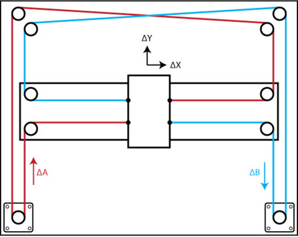
With this setup, the movement of a single motor creates diagonal motion. To create movement along the x or y axis, both motors have to run at the same time.
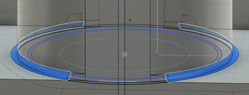
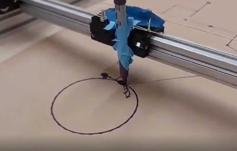
> The next step was hook up the motors (now dubbed motors a and b) to the machine and to test some example commands. The motors, in the modular-things environment, came with 2 types of directions: relative movement and absolute movement. Relative movement would take input x, y coordinates and add them to the current absolute coordinates, while absolute movement would go to the absolute x,y location given regardless of starting position. We taped a sharped to the place the end effector would be and ran some absolute coordinates to draw a circle (aka sending cos(x) * radius, sin(x) * radius locations in a for loop). This was the result:
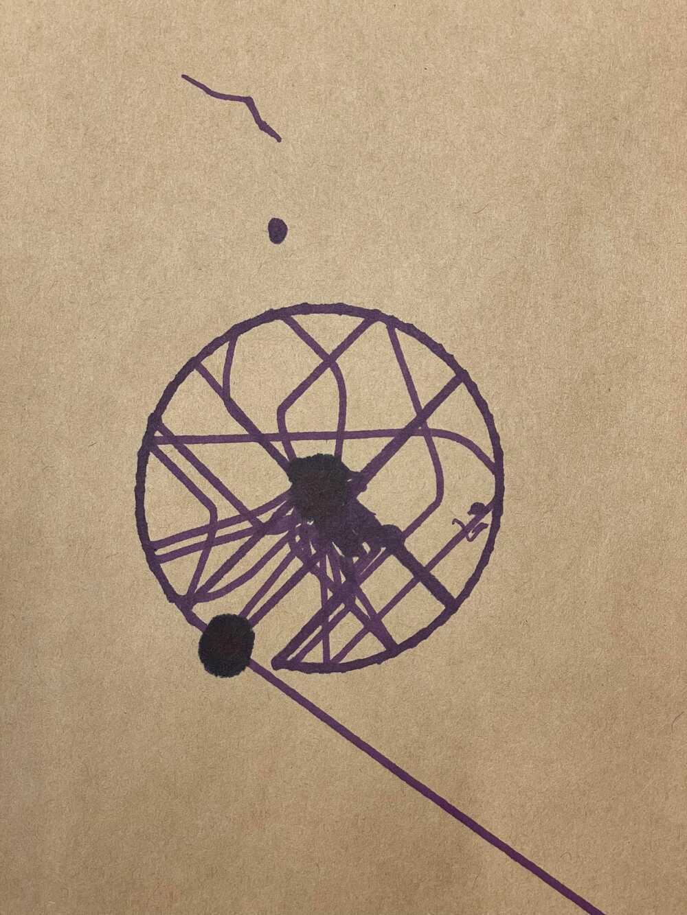
> The random dark dots are not part of the drawing. Since we did not have the end effector that would lift the sharpie up and down, it would bleed out onto the paper when the machine was static.
> Even though we gave just the locations of the outside of the circle, the machine traveled in and out of the circle, drawing different parts of the outer ring at different times. We concluded at this point that the "createSynchronizer([amotor, bmotor])" function that tied the motors togther did not account for the fact that the motors did not function in x,y -- as mentioned before. Given this distinction, we began to refer to the input coordinates as x,y coordinates and the coordinates necessary load into "createSynchronizer([amotor, bmotor])" as a,b coordinates. Given the setup of the corexy system, we found that the relationship between the x,y and a,b coordinates were as follows:
> a = x + y
>
> b = x - y
>
> We set up intermediary relative and absolute movement functions that would complete the x,y to a,b transformation for us. Once we did this, the circle was drawn as expected:
> With these function established, it was time to set up a homing/ calibration mechanism. Since the commands coming from software would be absolute coordinates, we wanted to home the machine, set (0,0), and then run the absolute coordinates. To home the device, our initial idea was to run the end effector slider into the y axis and then run it into the x to get it into the bottom right corner. We would have the machine run its length + 1 in both axes to ensure we made it to the bottom corner. At this point, we would set (0,0). Later on, we got 2 small circuits with buttons that we attached to locations where the end effector would collide with the outer machine. Rather than stall the motors by ramming the end effector into the wall, we would move the end effector until both of these buttons were being pressed, indicating that we were in home postition.
> Next, we focused on getting the code to read the outputs of the software. The software was written in python and produced commands as a list of tuples. Each tuple contained x, y, and z values. The plan was to read the x,y values and send them to the motors while reading the z value (binary value) into a conditional that would tell the end effector when to pick up and put down the drawing utensil.
> We copy and pasted an example list into the code and ran into issues of the pen randomly ramming into the sides of the machine, even though the inputted picture coordinates were well within the drawing box. We later realized that javascript does not read tuples. Rather than sending an error, it would read whatever garbage value that took the tuple's place and send our pen to far away places. We fixed the tuple issue and sent our first drawing to the machine, an orange. Here are the results!
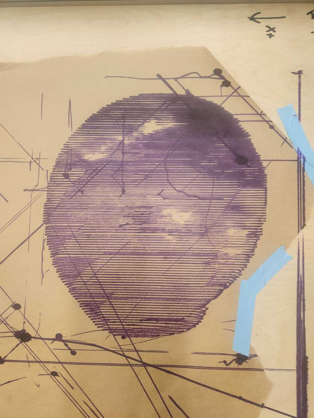
> an orange with a little shadow!
> We found some bugs in the modular-things, specifically this block of code needed a try and catch block as we were having program terminating errors otherwise due to the firmware 'resetting' expectations on what coordinate information it should be communicating.
> Quentin and Jake gave us some helpful things to keep in mind while using modular-things:
* Because it is a js application, we don't want to be switching browsers as that dictates running power (so keep the console tab in a conjoined pane to the browser)
* You don't have to manually unplug the machine to stop it, you only need to refresh in the browser
# All the parts together:
> Here our some of our prints!
<!--  -->

> Kirby!

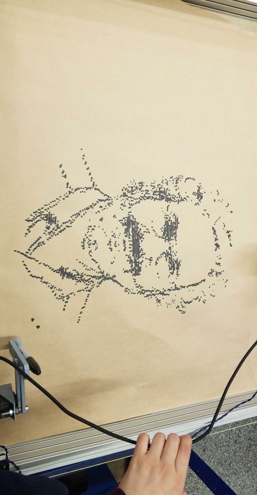
> and Neil.
<!-- # [Accessibility](https://accessibility.mit.edu/)
> MIT is committed to providing an environment that is accessible to individuals with disabilities. We invite all to learn
about captioning and accessibility of digital content, and to report any accessibility issues or captioning requests in
the form link on this page.
```url
https://accessibility.mit.edu/
```
#### Note on Math Equations with \\( \LaTeX \\) (using [MathJax 3](https://www.mathjax.org/))
1. Inline equations: only `\\(`/`\\)` works, instead of `$`/`$`. Example: \\(f(x) = \int_{-\infty}^\infty \hat f(\xi)\,e^{2 \pi i \xi x} {\rm d}\xi\\)
LaTeX code:
```latex
\\(f(x) = \int_{-\infty}^\infty \hat f(\xi)\,e^{2 \pi i \xi x} {\rm d}\xi\\)
```
2. Display-mode equations: both `$$`/`$$` and `\\[`/`\\]` works. Linebreaks `\\` in multiline equations needs to be replaced as `\\\\`.
Example:
\\[
\begin{aligned}
\nabla \times \vec{\mathbf{B}} -\, \frac1c\, \frac{\partial\vec{\mathbf{E}}}{\partial t} & =
\frac{4\pi}{c}\vec{\mathbf{j}} \\\\
\nabla \cdot \vec{\mathbf{E}} & = 4 \pi \rho \\\\
\nabla \times \vec{\mathbf{E}}\, +\, \frac1c\, \frac{\partial\vec{\mathbf{B}}}{\partial t} & = \vec{\mathbf{0}} \\\\
\nabla \cdot \vec{\mathbf{B}} & = 0 \end{aligned}
\\]
LaTeX code:
```latex
\\[
\begin{aligned}
\nabla \times \vec{\mathbf{B}} -\, \frac1c\, \frac{\partial\vec{\mathbf{E}}}{\partial t} & =
\frac{4\pi}{c}\vec{\mathbf{j}} \\\\
\nabla \cdot \vec{\mathbf{E}} & = 4 \pi \rho \\\\
\nabla \times \vec{\mathbf{E}}\, +\, \frac1c\, \frac{\partial\vec{\mathbf{B}}}{\partial t} & = \vec{\mathbf{0}} \\\\
\nabla \cdot \vec{\mathbf{B}} & = 0 \end{aligned}
\\]
```
___ -->
<small>&copy; 2022 [HTM(A)A'22](https://fab.cba.mit.edu/classes/MAS.863/) [EECS Section](https://fab.cba.mit.edu/classes/MAS.863/EECS/). Template adapted by [Y. Liu](https://fab.cba.mit.edu/classes/MAS.863/EECS/people/Yang/), powered by [`strapdown.js`](https://ndossougbe.github.io/strapdown/), [Markdown](https://ndossougbe.github.io/strapdown/demos/markdown_syntax.html), and [MathJax 3](https://www.mathjax.org/) for \\(\LaTeX\\) rendering.</small>