This website is for the course How to Make (Almost) Anything (Fall 2022)
Contact Me
You can reach me at
alexiaasgari@gsd.harvard.edu
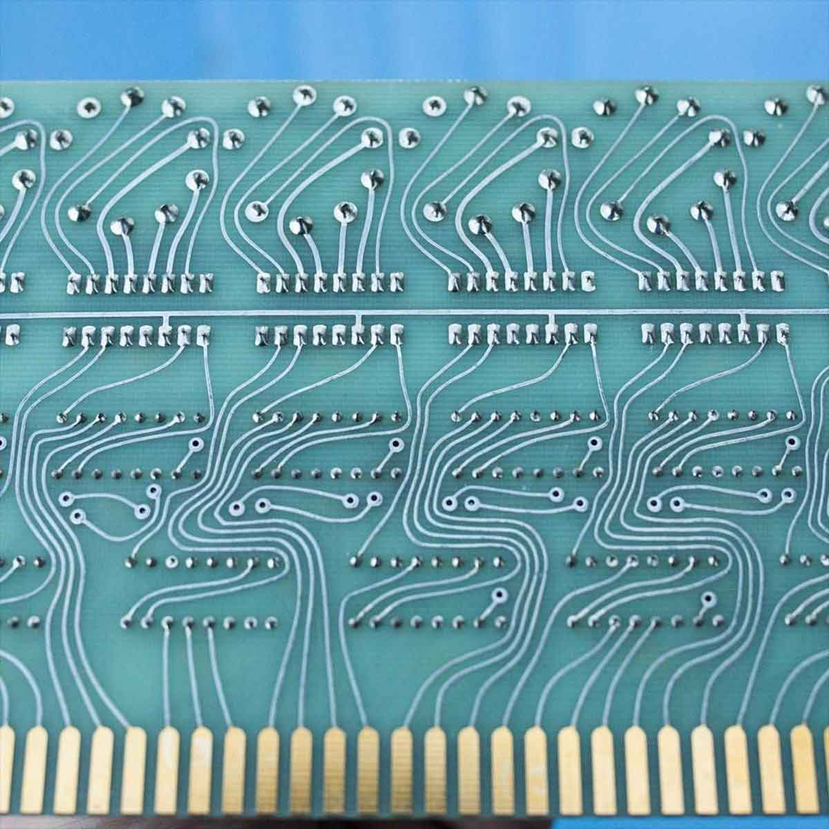
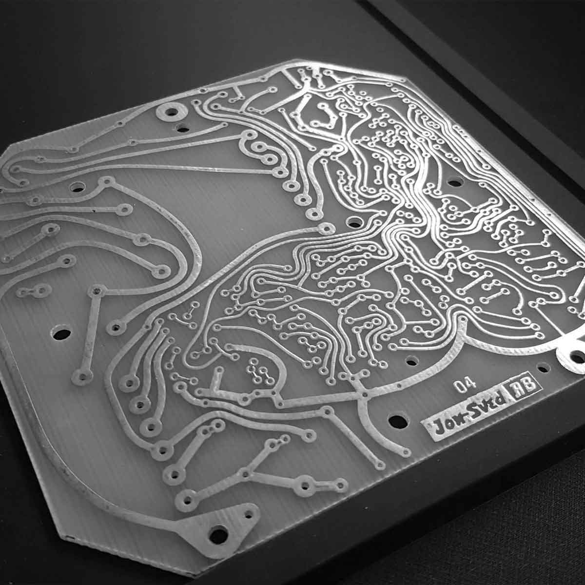
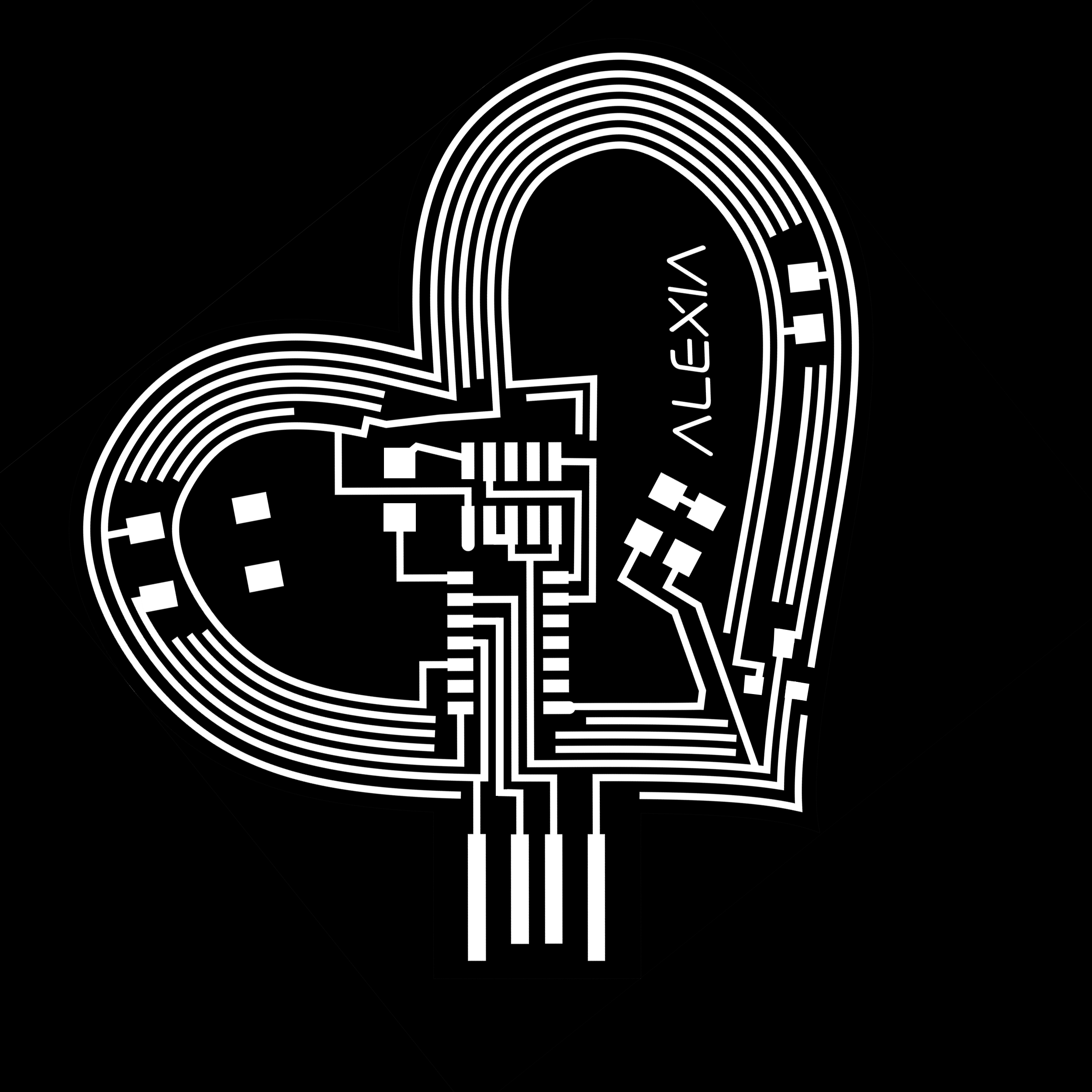
Discussing circuit board asthetics with Leo, I was introduced to hand drawn vintage circuit board traces from the 1980s. Though a relic from the past, I found them futuristic and beautiful. I wanted to emulate these curved lines in my own board
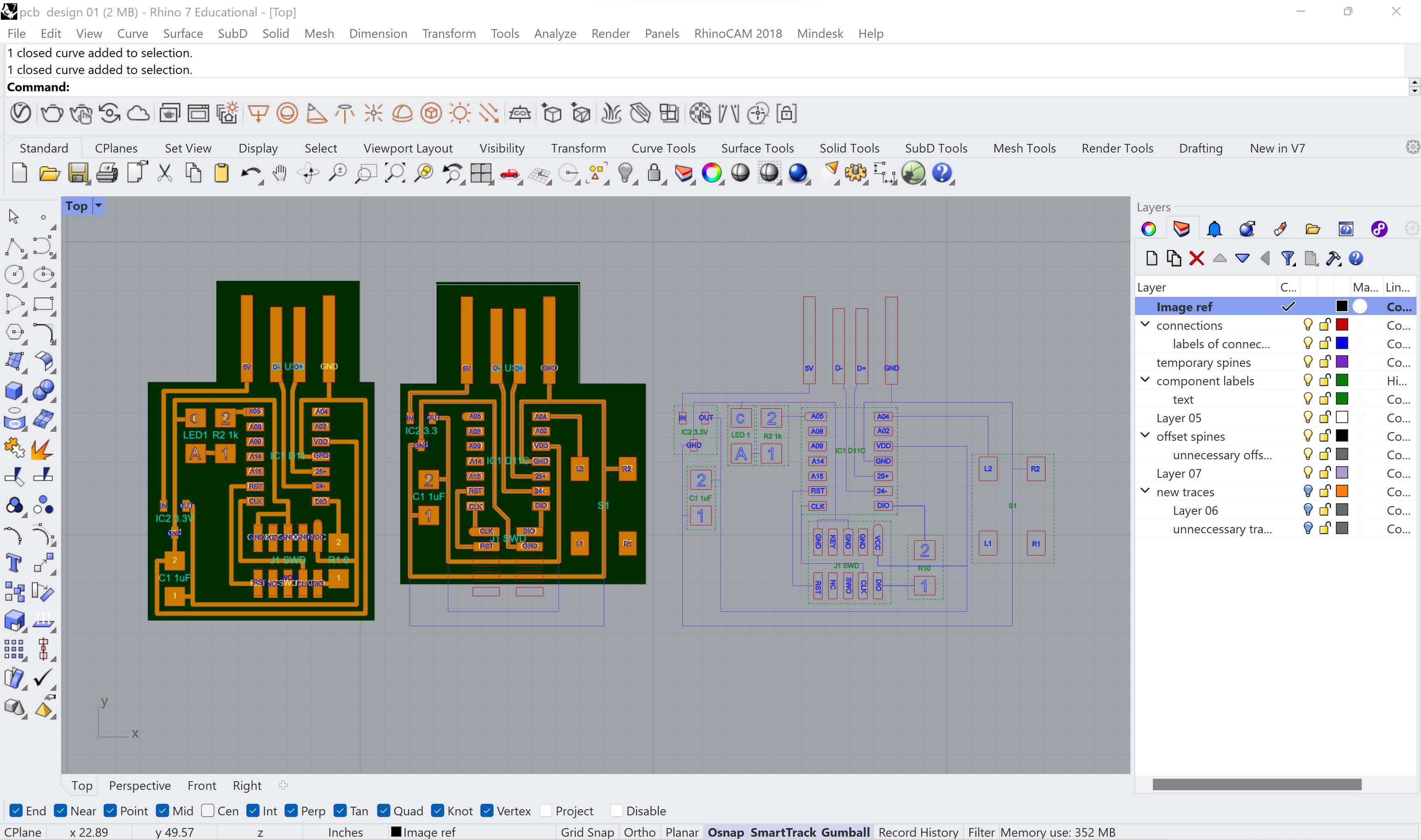
Using 2 boards as references from SVGPCB, I began mapping connections that needed to be made to combine the boards in Rhino.
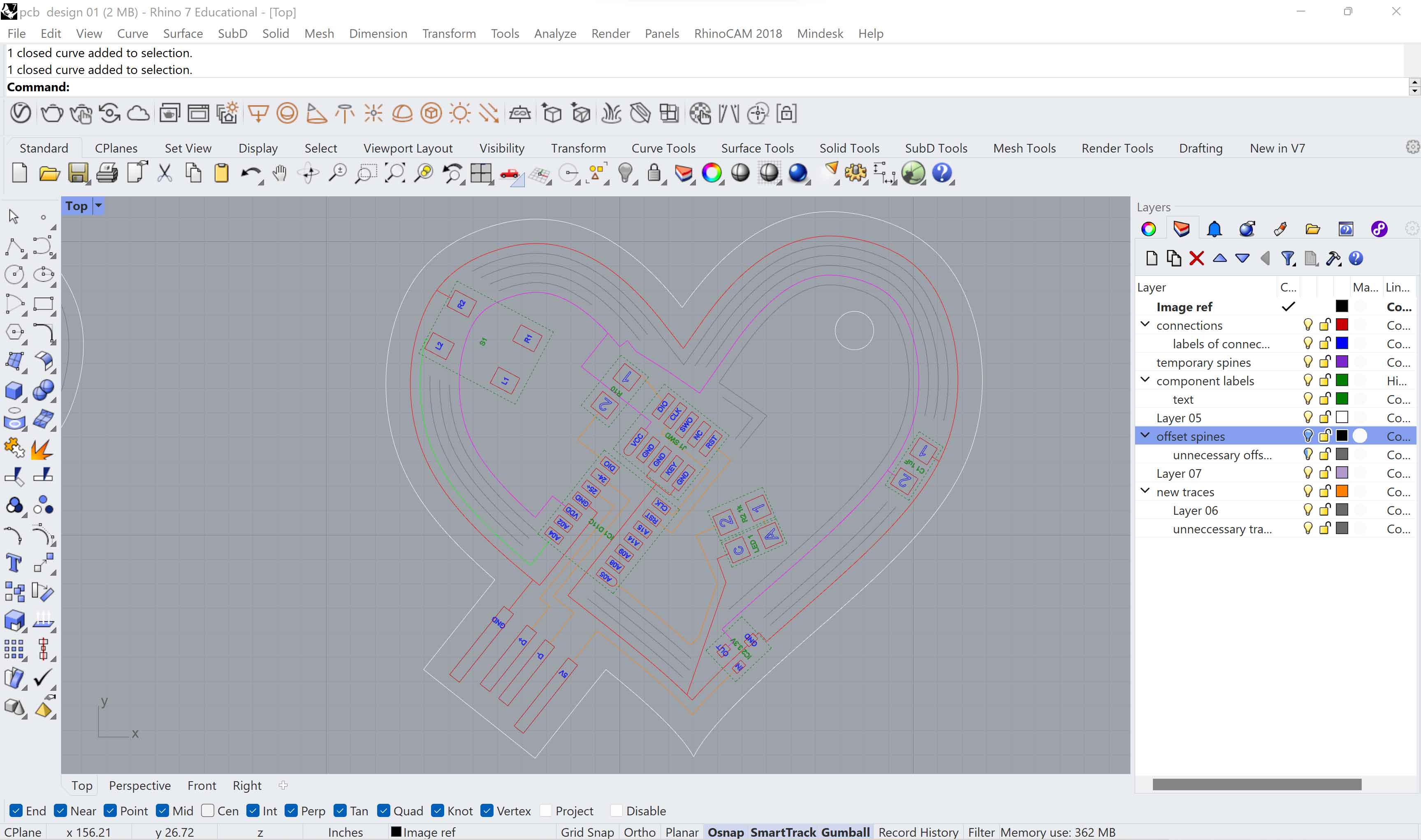
I remapped these connections onto a heart form, with a jagged heart break line in the center. I used the Rhino offset function to create heart shapped traces that in fact functioned to carry current. Some traces remained for aesthic purposes.
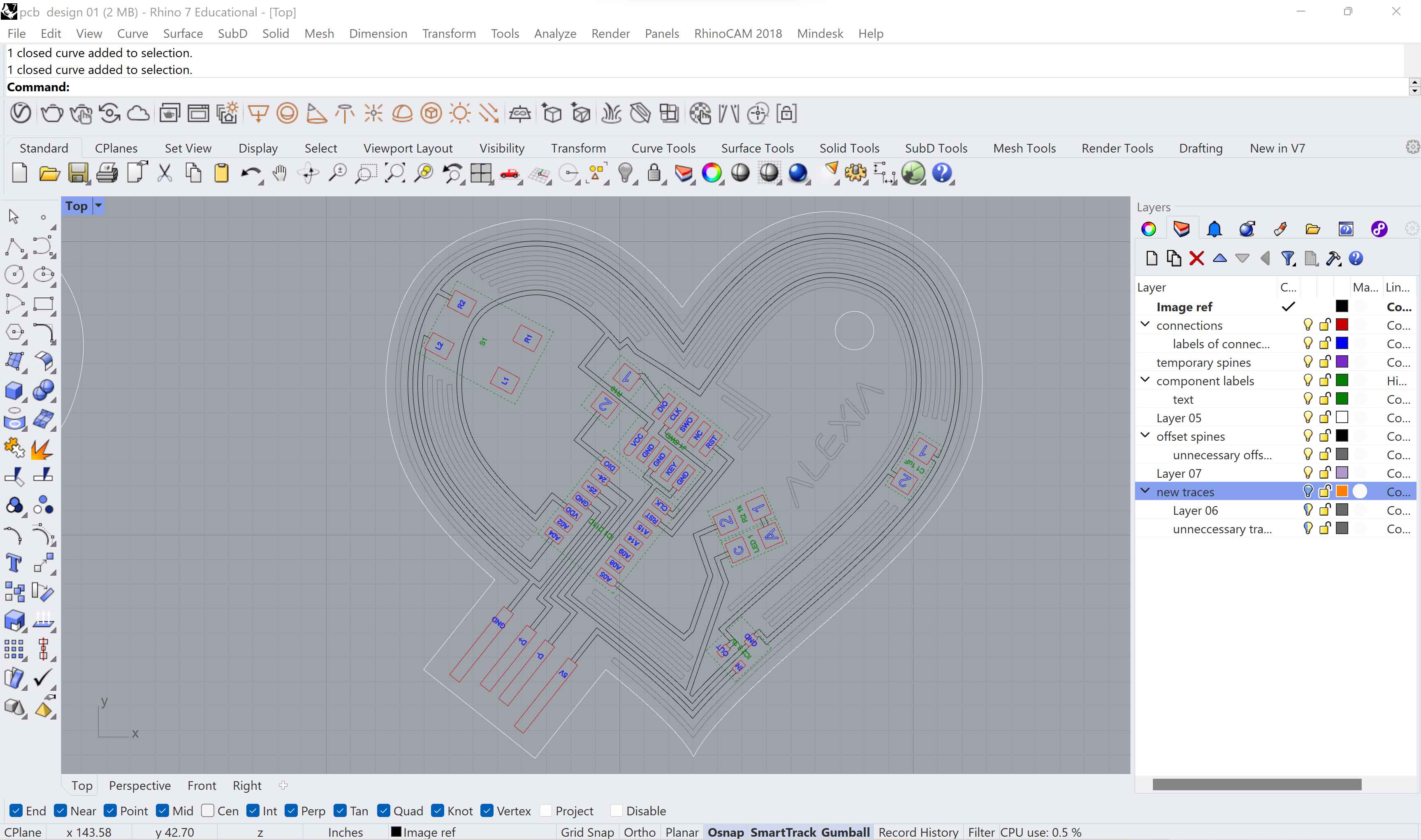
I then added thicknesses to the traces.
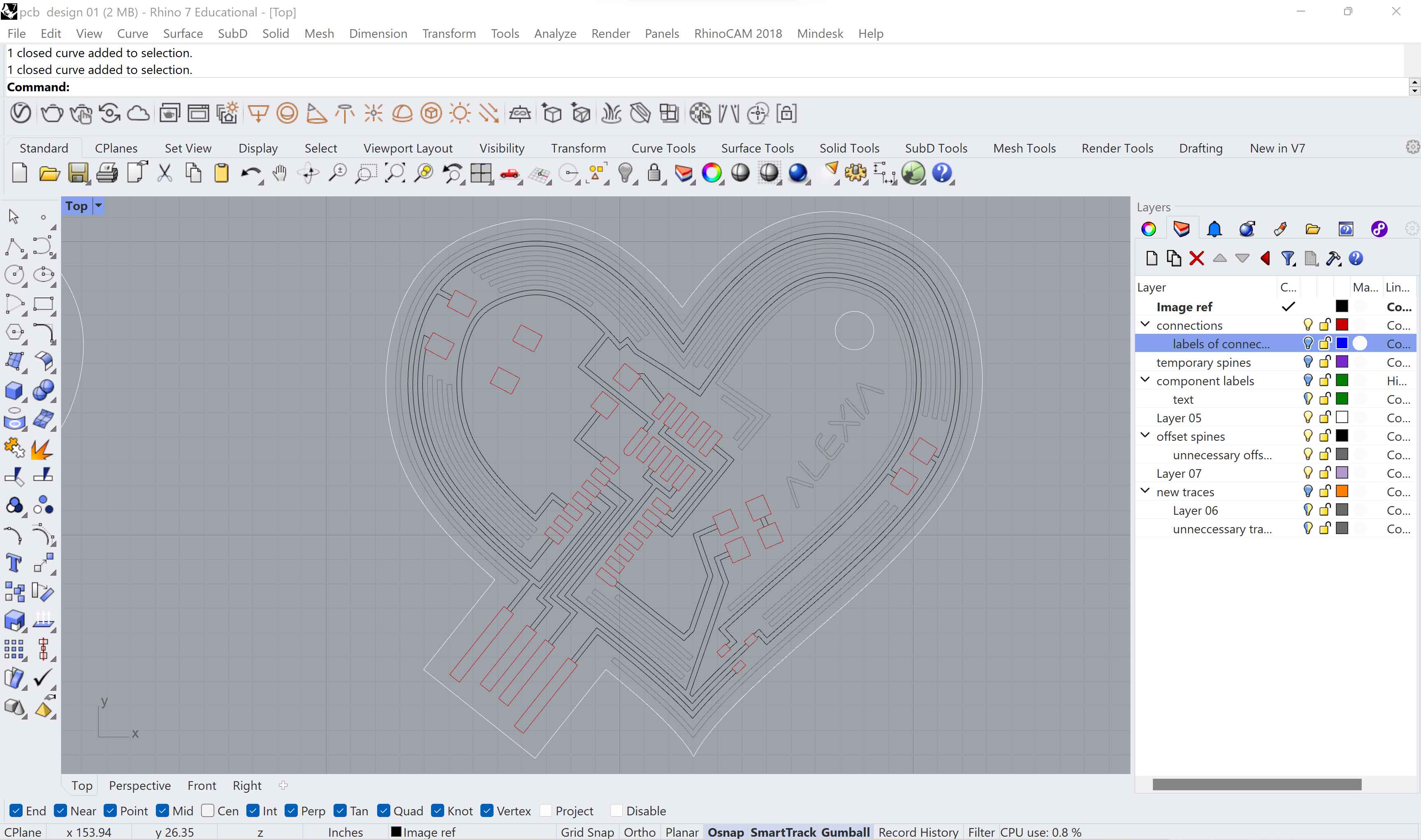
I exported the unlabeled version to illustrator
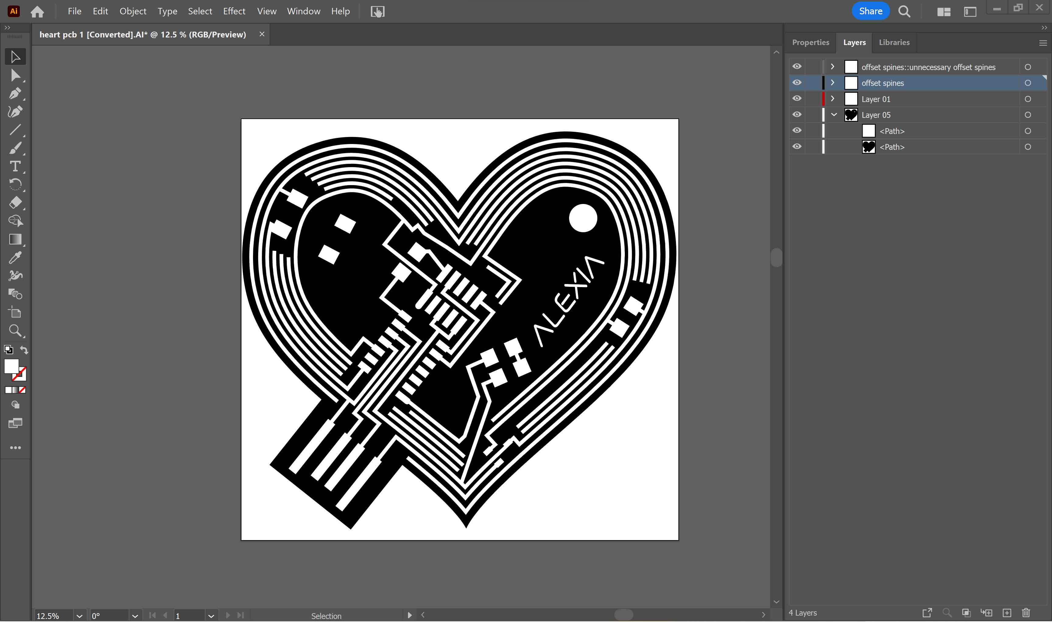
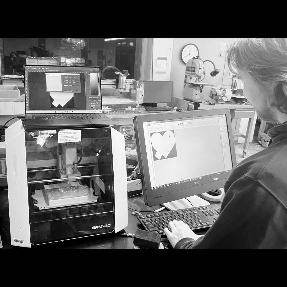
In Adobe Illustrator I colored the board to prep for milling.
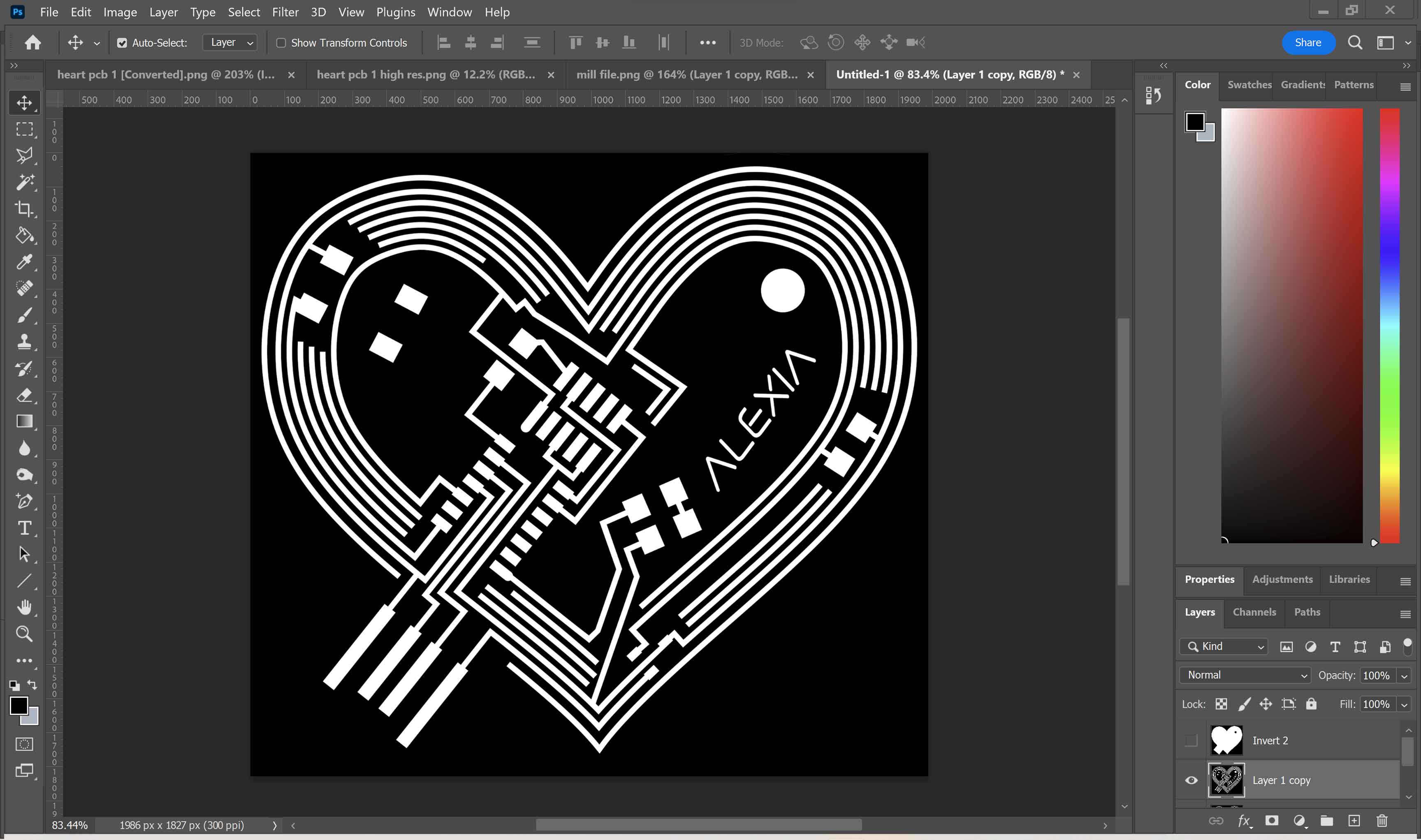
There where small adjustments here and there I made in photoshop after seeing the mill path

Here are my most recent working files.
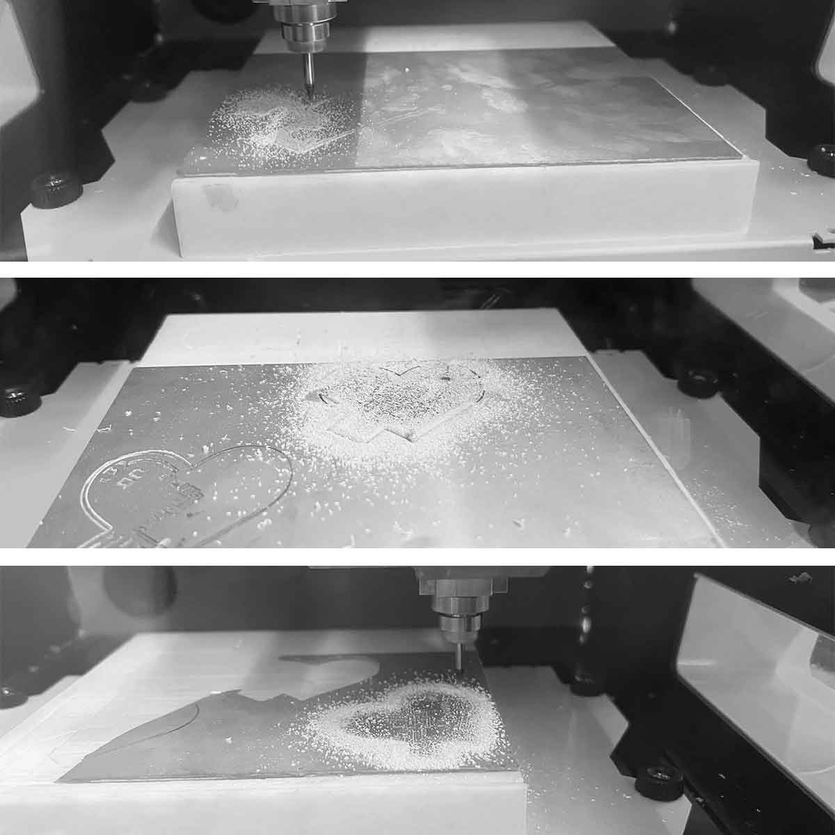
I was then ready for milling. In my first attempt, I learned part of the base board wasn't leveled so I was advised to only cut in one corner of the machine. In my next attempt, I didn't check the preview closely enough to see it wouldn't mill some traces seperate. In my 3rd attempt I finally had a working file.
This is the imfamous image of Leo helping me darken the boarders in microsoft paint as I was experiencing technical difficulties in photoshop, and my second attempt wasn't cutting through.
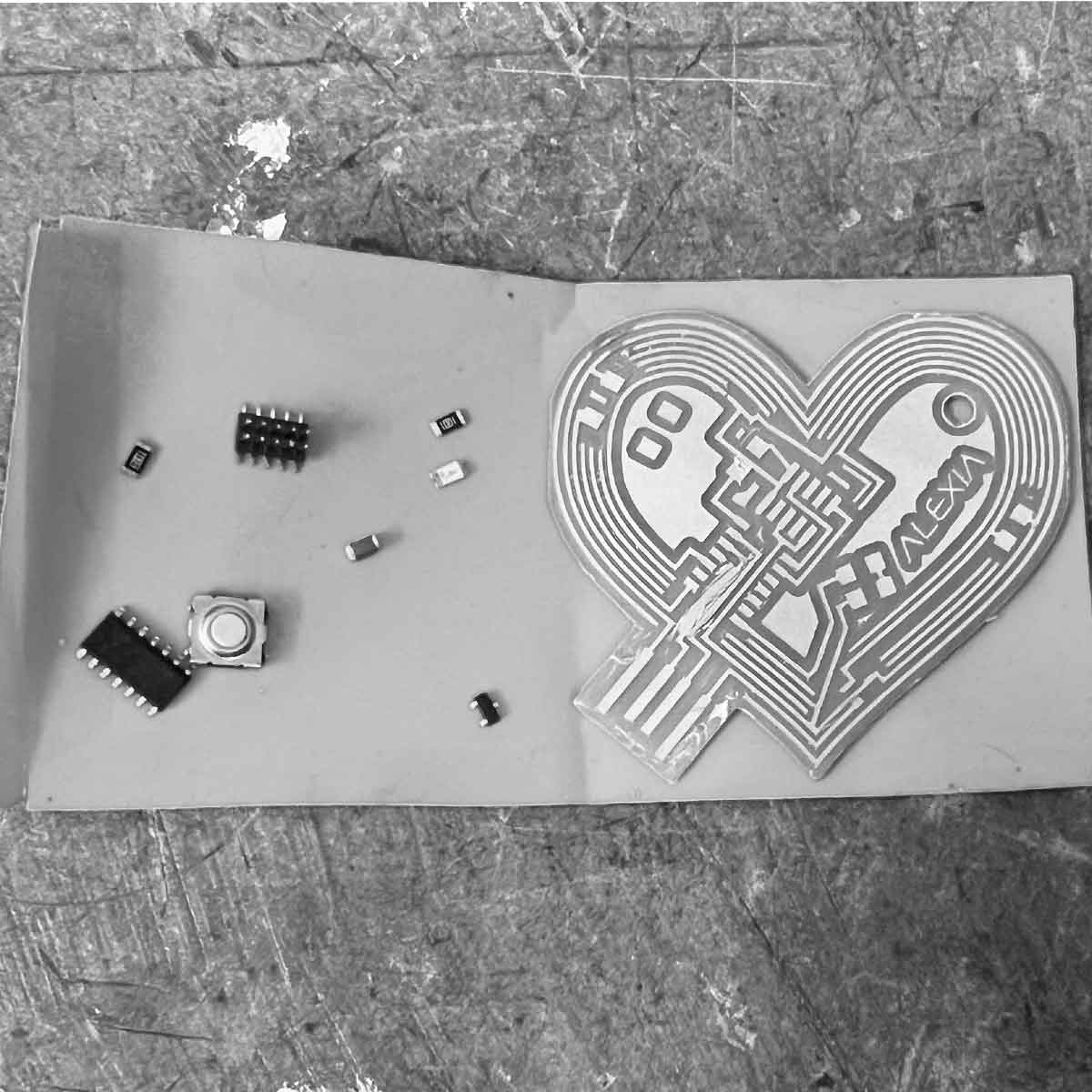
Once I had a board I gathered all my components, asking my peers and one of the TAs for tips on orientation, etc.
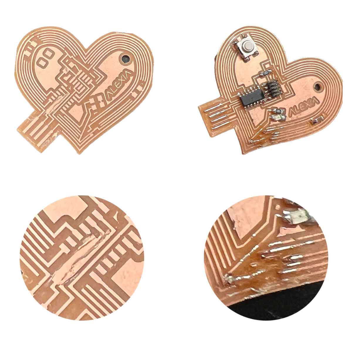
This photo shows the joint traces of board 2 and the horrible soldering disaster of board 3 where I destroyed some traces. Oh well, you live and you learn.
I set out to mill again, this time to have a new glitch on a different machine. Claire sat with me to help me solve it and Noy ultimatley joined having a solution. Thank you to both of them as this was super overwhelming. The machine would go to the correct start/end points but just air cut the outline for no apparent reason.
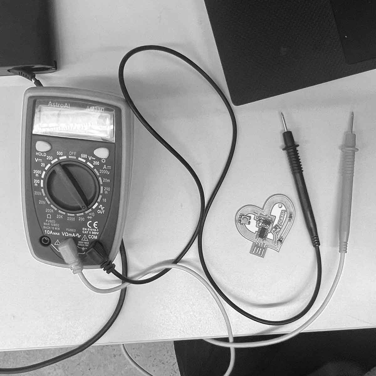
I used the multimeter to test for shorts and removed solder to resolve any shorts that I noticed. One thing that took too long to notice was that I attached one of the components backwards.
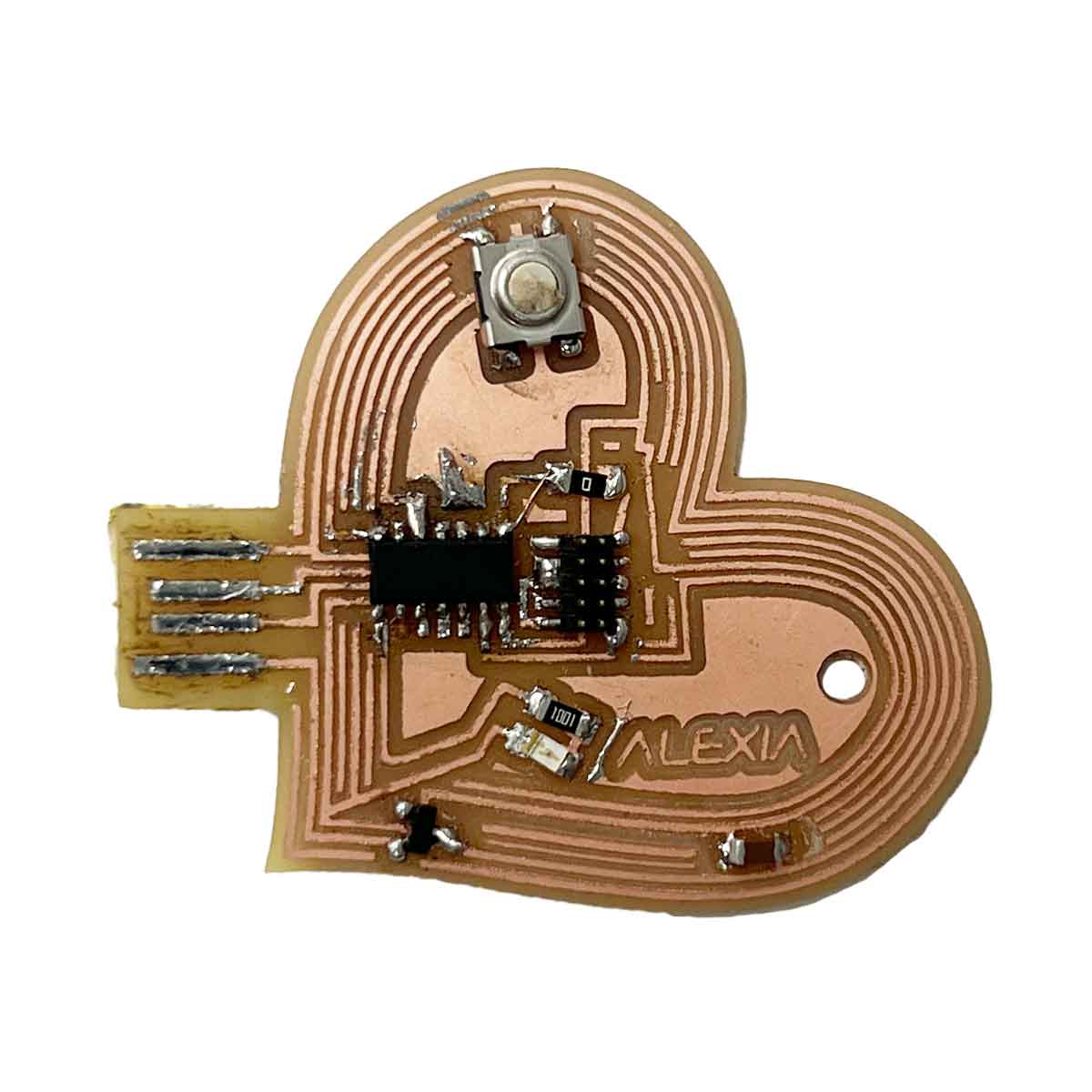
Trying to flip the backwards component, I tore out a trace. Leo helped me reattach the component and used a wire to reconnect the foot to the broken trace. I also accidentally melted the top of the button, so the board is looking a bit rough, but I suppose its an aesthetic that I can pretend is intentional.
I faced many delays. I still do not have access to Eagle, after reaching out for help. SVGPCB was great but didn't allow me to achieve the vision I had. I moved to rhino since I was more familiar, using SVGPCB as a reference. I hand drew the traces using offset functions to be careful about distances. I wanted to go for a hyperfem aesthetic that we don't often see in electronics design, including a hole so I can wear it as a pendant or key chain.
In a way I think my aversion to SVGPCB was driven by my dislike of standard electronics forms. I think traces can be "cute" and fun. By using a familiar software, I was able to achieve interesting results.
Also to note, I recently had a lecture by Shelby Elizabeth Doyle discussing feminism in computational design. She actually did a residency in a fab lab in Maine recently and is an alumni of the class. Having just designed this PCB with hyperfem aesthetics, I felt affirmed.