This website is for the course How to Make (Almost) Anything (Fall 2022)
Contact Me
You can reach me at
alexiaasgari@gsd.harvard.edu
Stepper Motor-Servo Motor
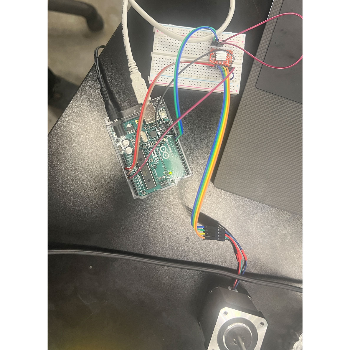
This was the bread board set up, using an arduino uno and it was working.
I was super grateful because Nathan provided me his old stepper to arduino script using firefly in grasshopper.
script on: my HTMAA archive

Here is a screenshot of the arduino iDe interface to connect to grasshopper.
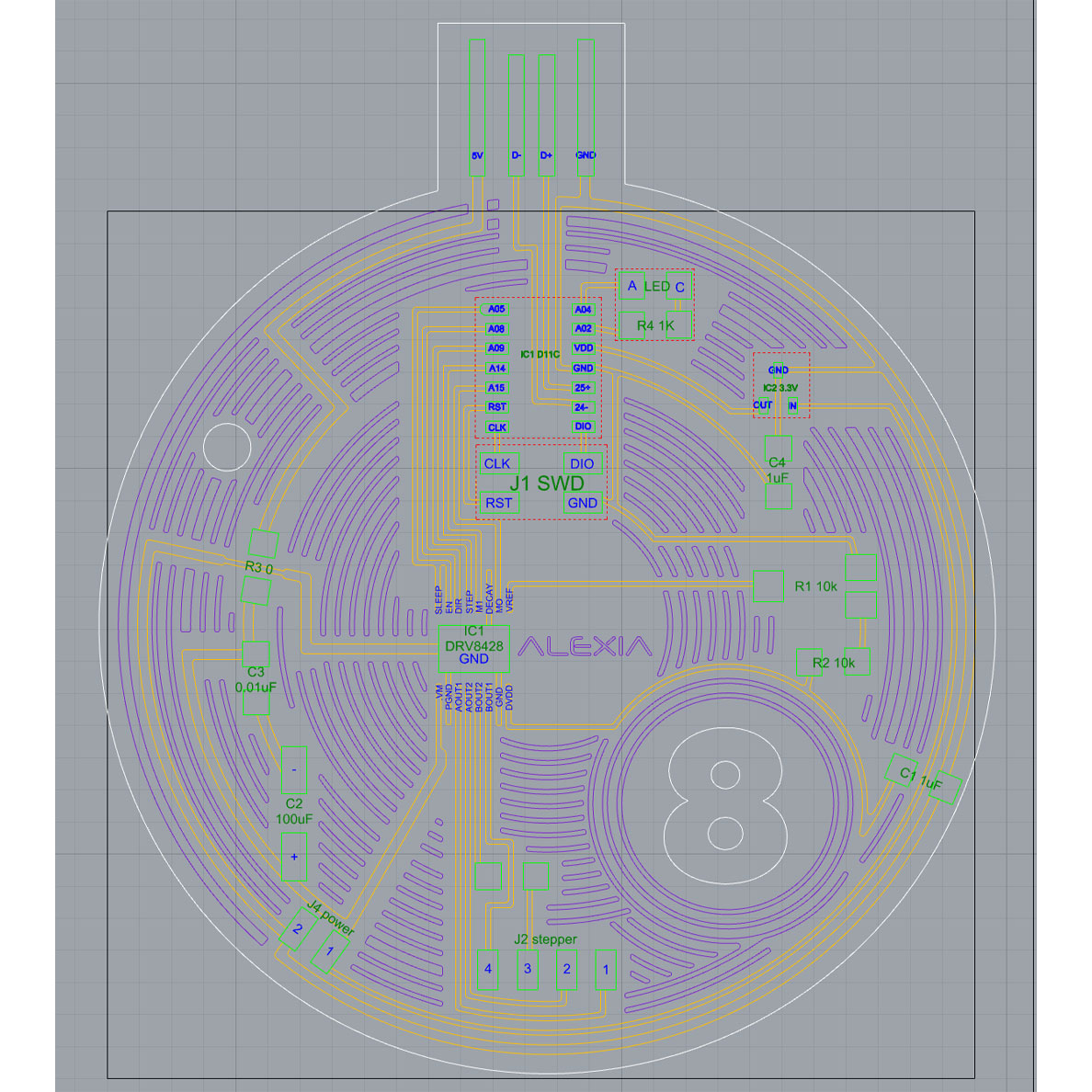
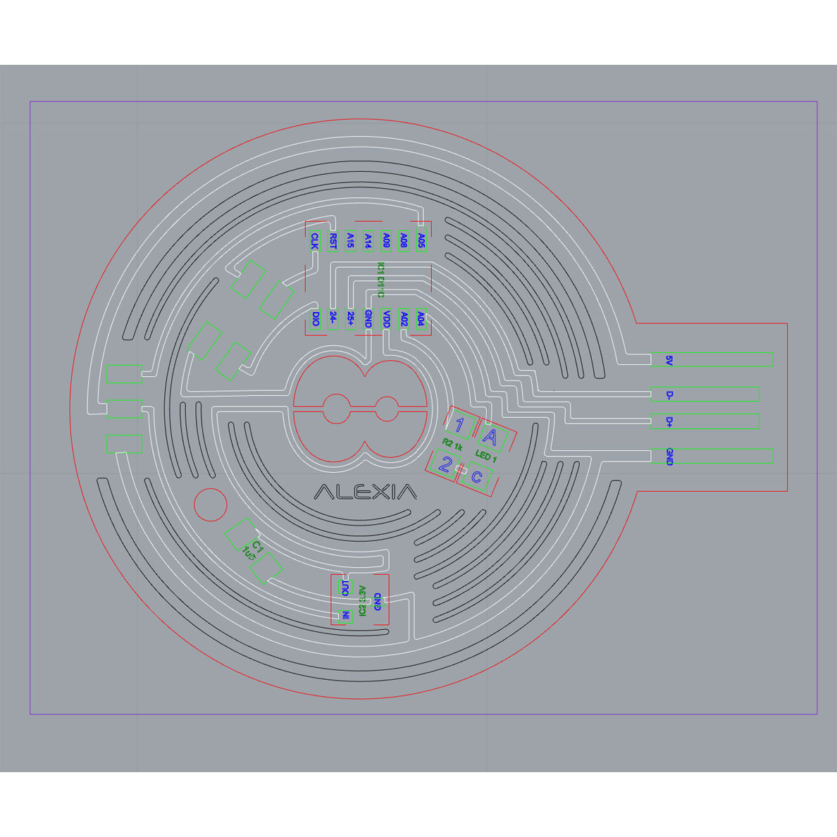
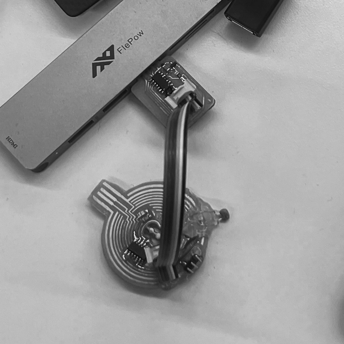
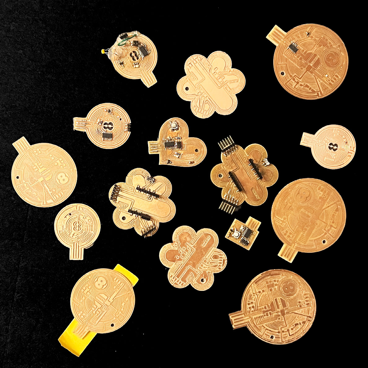
Based on a billiard ball, I designed a board for a motor.

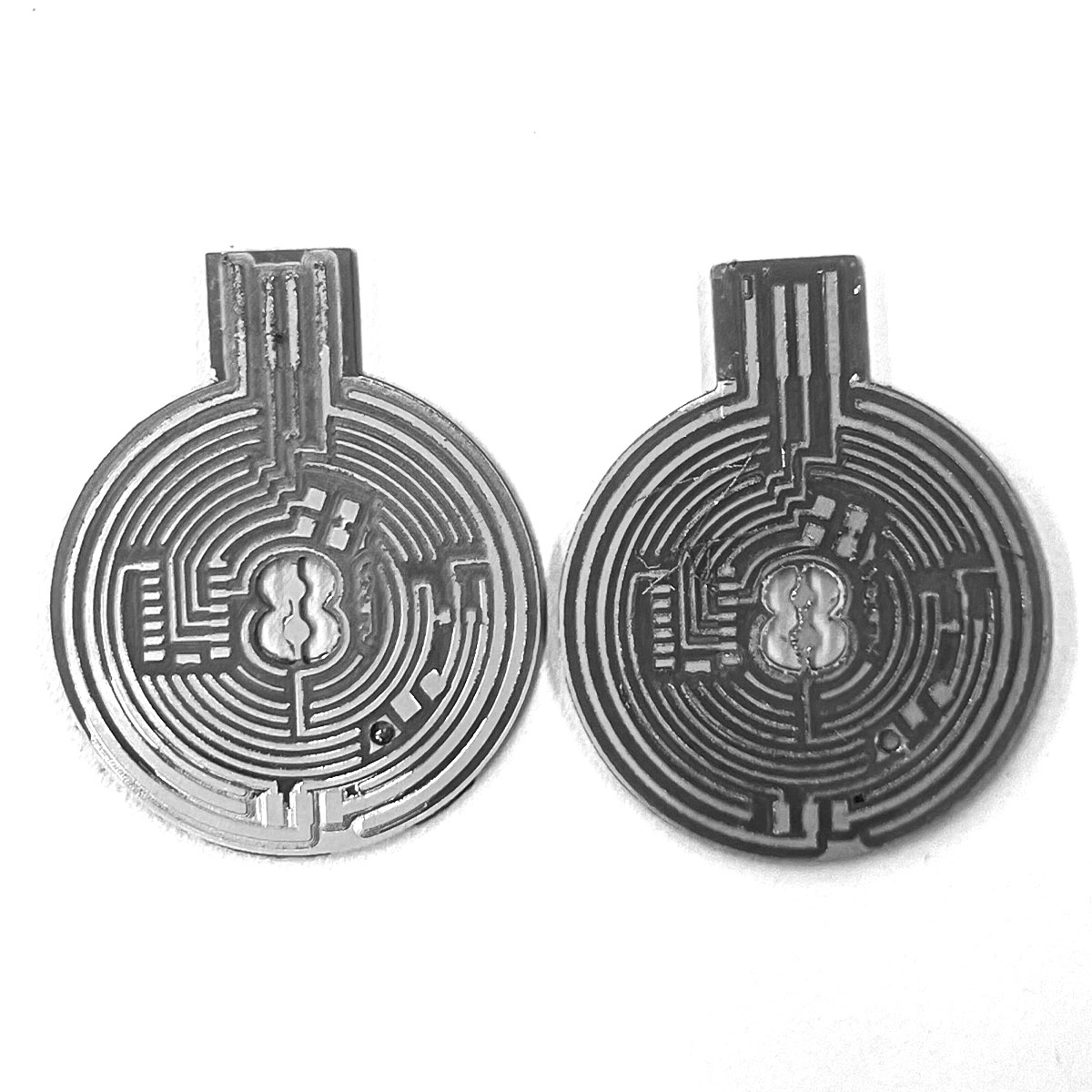
These are the traces.

Stepper outline


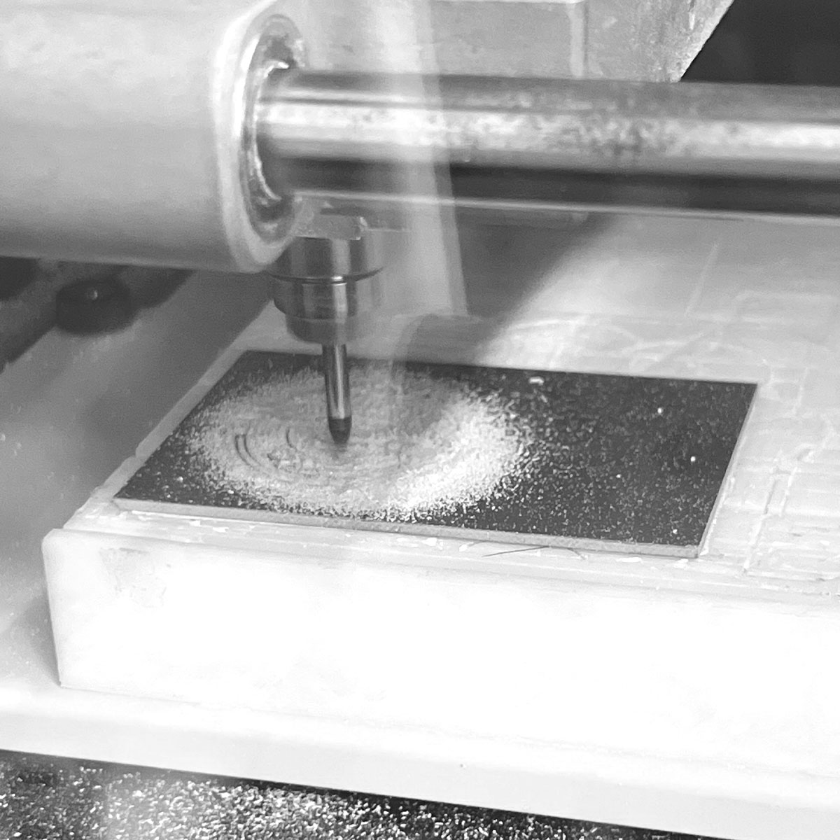
There was a new copper clearing tool in mods so I preped two files for the front and back just in case i had the chance.
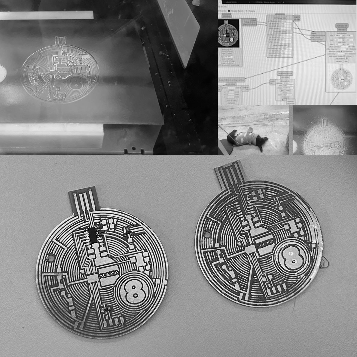
I actually ended up milling several boards, 2 of which had to be scraped because I just didn't check the dimensions. Others had faulty traces from warped copper and there was one that was fine that I started to work on.
Unfortunatley, Treyden warned me we didn't have the processor I needed to make it work.
I moved on to designing a servo based off this one on the HTMAA website : hello.servo-D11C


This was a mini version of my billiard ball design. Refer to final to see further progress on it.
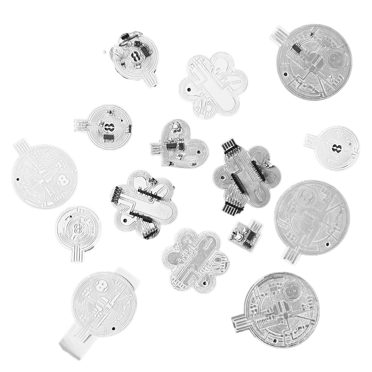
moral of the story: a lot of boards were made.
For this week's output device I first chose to design a board for a stepper motor. In the spirit of movement, my design resembled a billiard ball. I started by getting a motor working via a bread board, made with Nathan's help. I lost a ton of time with milling just due to forgotten measurements. Please learn from me and don't waste time and material!! On the bright side the practice helped build confidence.
Servo Motor
I've added the text on my servo explorations from my final project web page:

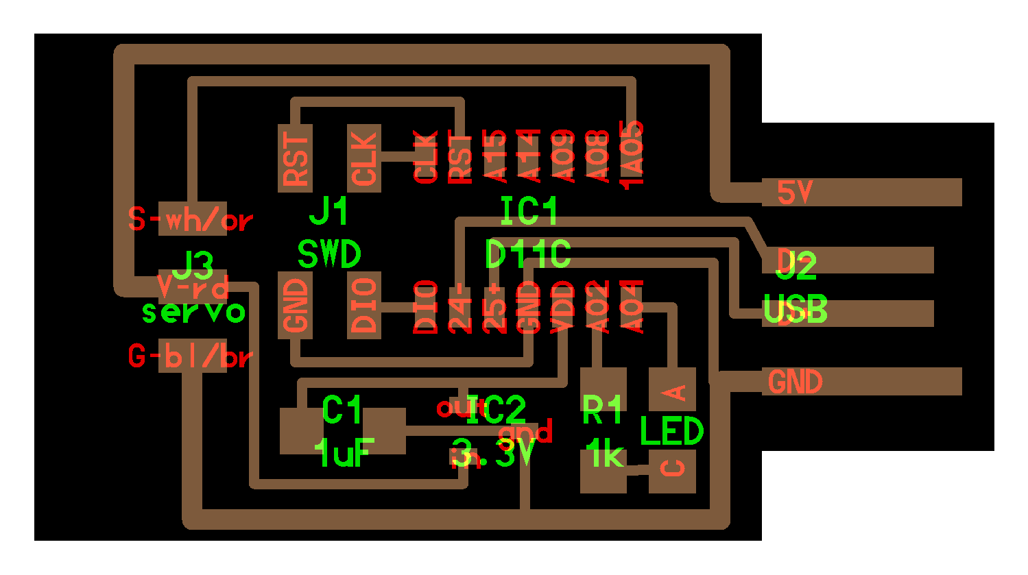
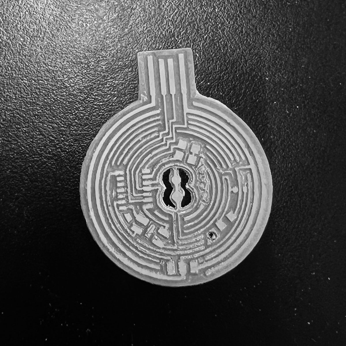
servo board traces (of course made to resemble an 8 ball because why make something unoriginal...well I'll tell you why haha)

servo board outline (another one of my hand drawn rhino designs)
here's the story of my attempts at making my own board to run a servo:
we start off strong with a broken bit. That means there is only one bit left in the whole lab.
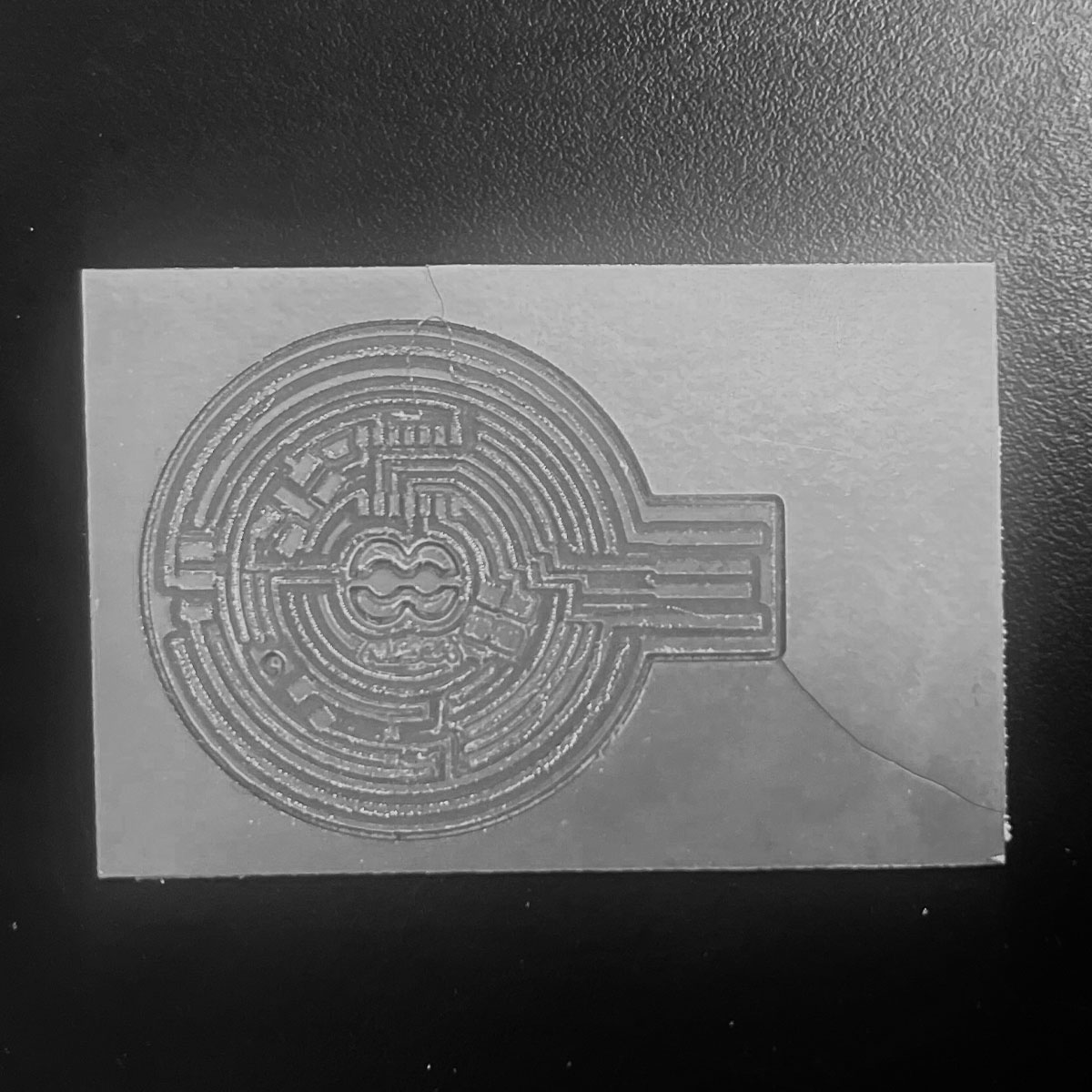
Next attempt was also a milling issue (at least it got closer. Maybe the board was warped. Not much to do when you are scrapping for materials. at least the second one milled well. I just needed some sandpaper to clear the copper strings between traces. Otherwise these artifacts of milling could cause shorts.
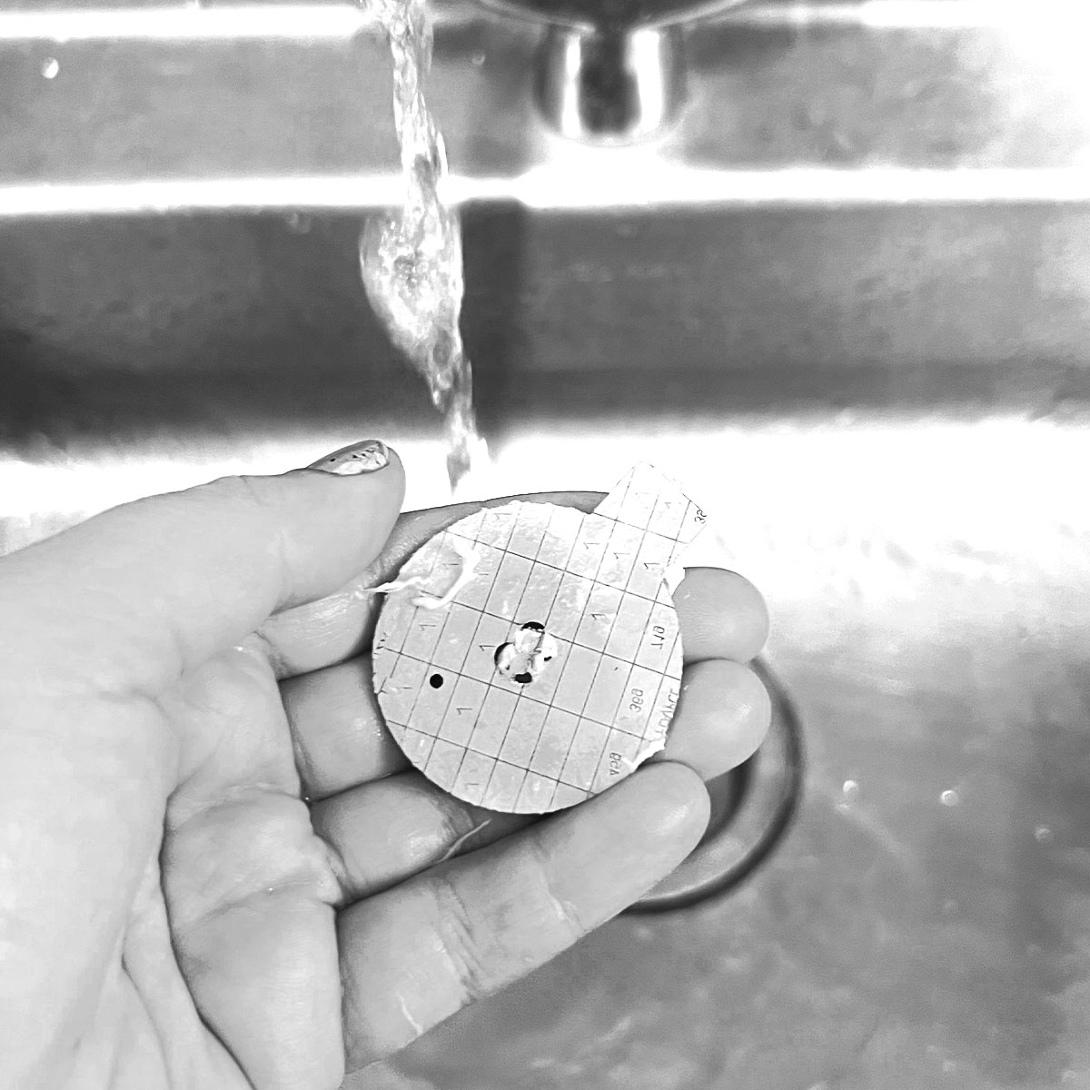
I also rinsed off the board in the sink to try to remove the stuborn leftover adhesive on the back (I find a slow pushing motion works best to take off adhesive if scraping won't work)
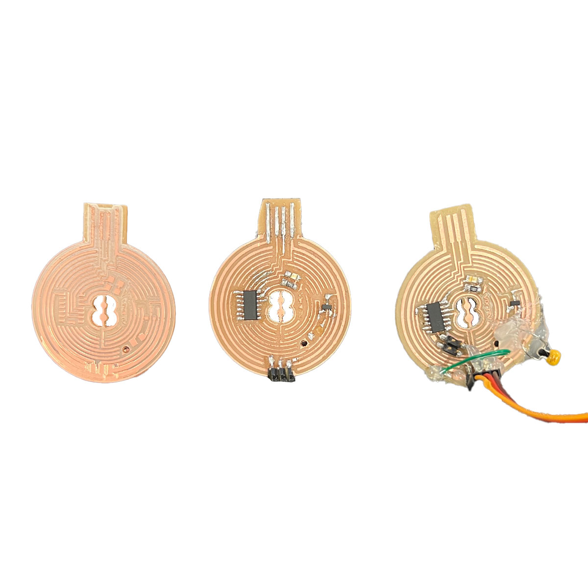
the story of this one is simple.
the process to make it went smooth...
...too smooth
Do you notice it?
NO PINOUTS FOR PROGRAMMING!


In the meantime we had a HTMAA Harvard Section group reunion at Queenshead. It really came in handy as i got in contact with Quentin to arrange to visit CBA and get all the parts I needed that we were missing in the Harvard lab
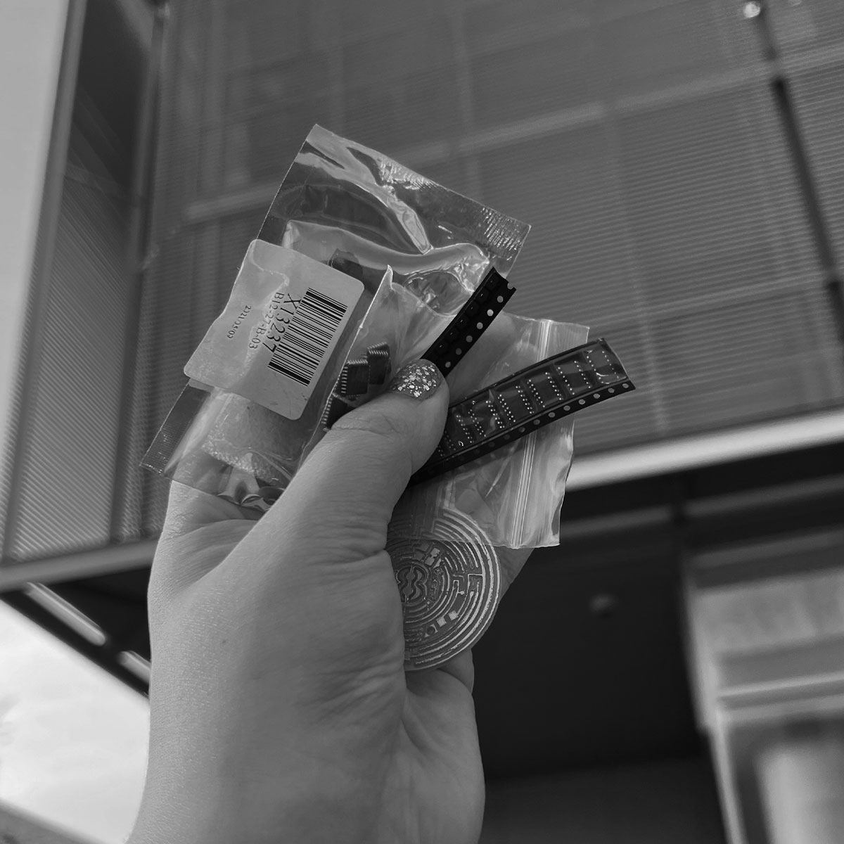
I was there at the Media Lab the next day to collect all the necessary parts. Thank you Quentin!
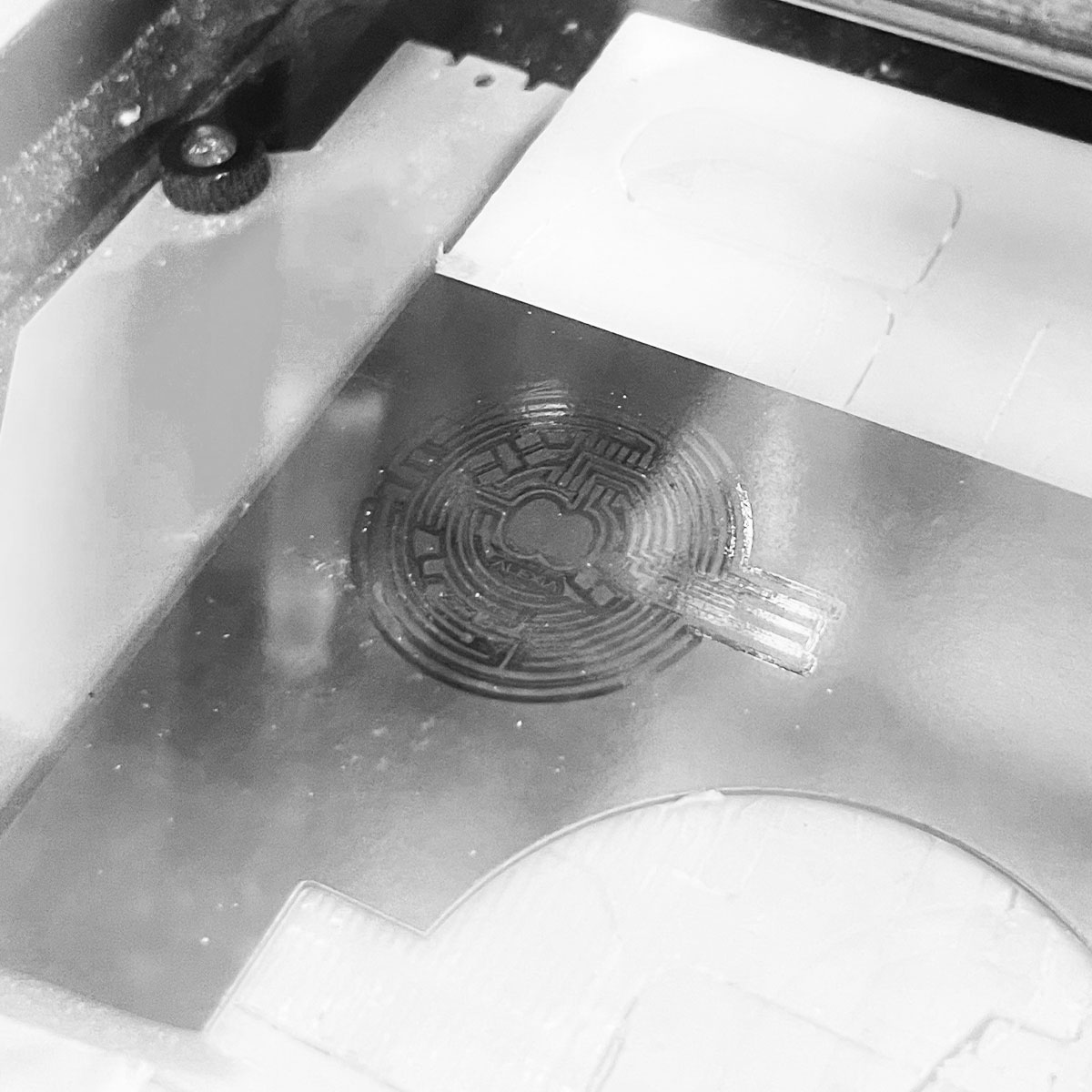
so it was back to milling
and of course something had to go wrong. I moved it before realizing it didn't cut all the way through.
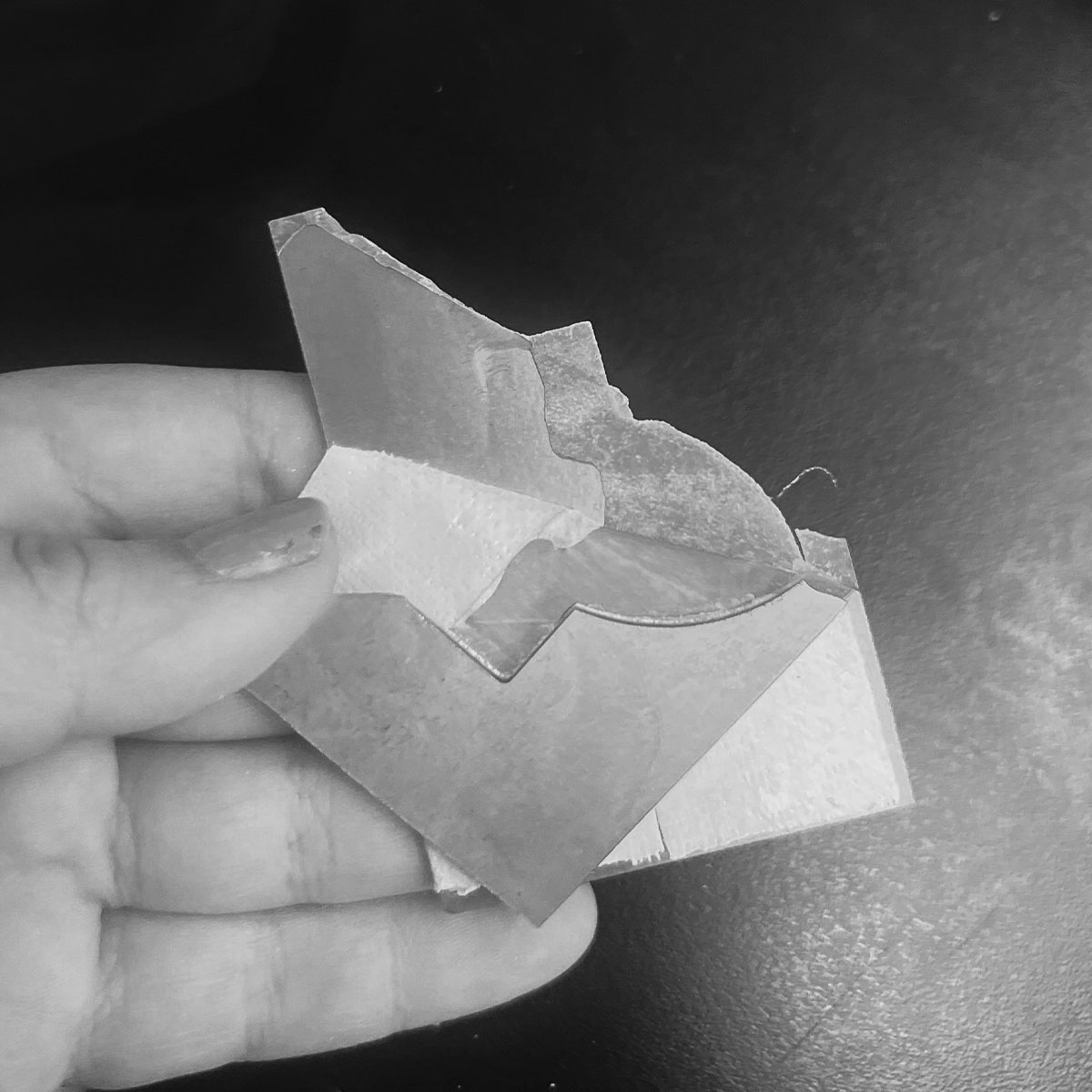
on th bright side, this made clearing copper off the back half much easier.
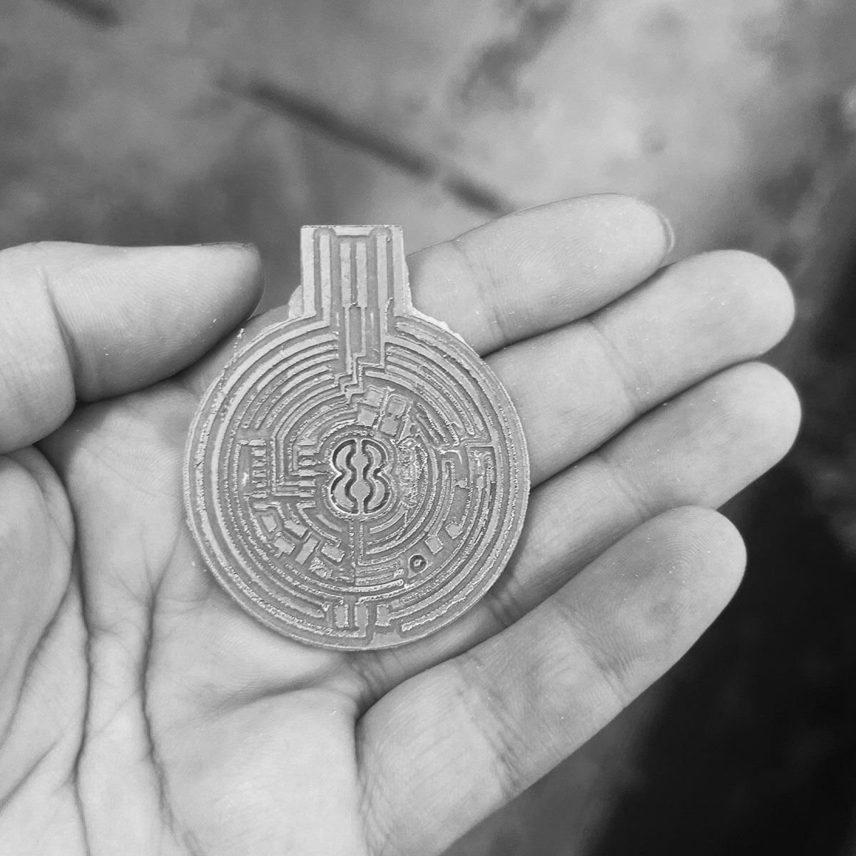
I popped it out
Then with the help of a knife and some sandpaper, I cleaned it up
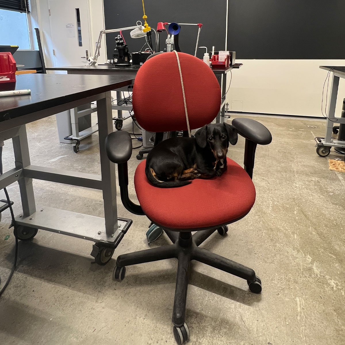
with my trusty lab partner Frankie, I was set up to solder again.
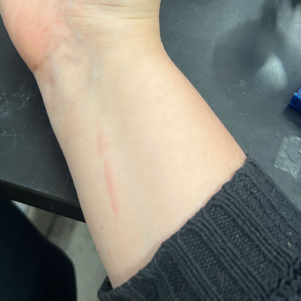
after dropping the iron on my wrist somehow
I finished soldering..almost
I needed a capacitor
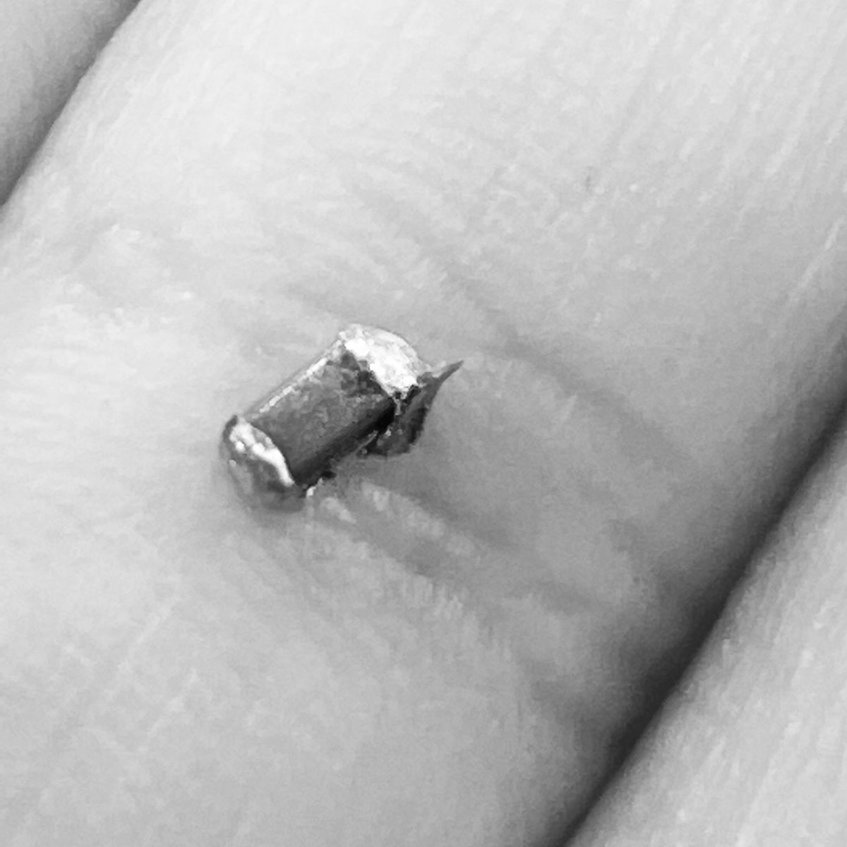
One issue.. the capacitors were no where to be found. I tried salvaging one off an old board.. and it clearly wasn't working out
Suvin dropped by and I was so thankful. He handed me one from a breadboard. I was so excited to have a capacitor to move forward with, I soldered it on before realizing it was the wrong one.
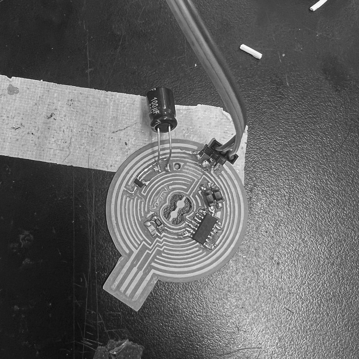
Okay, finally got the correct capacitor (breadboard one but logically should work).
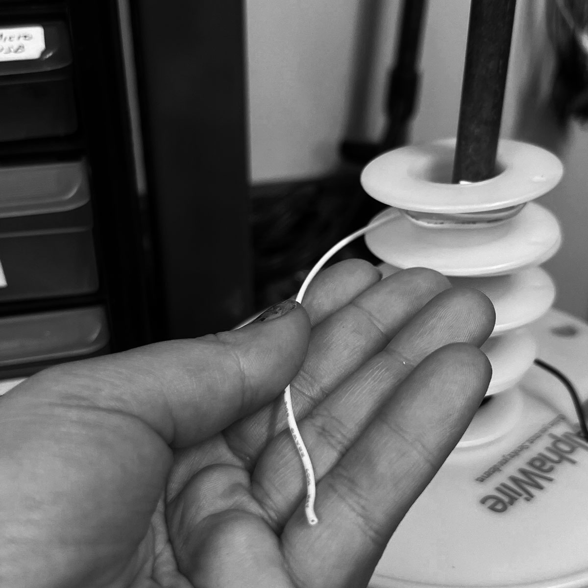
i broke a trace and needed to solder on a wire. the first wire I attempted was too rigid.
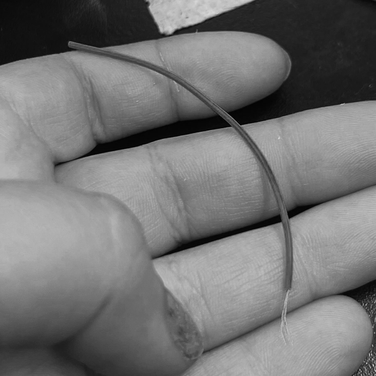
PK then advised me to cut a servo for the wire but unfortunately it was corded
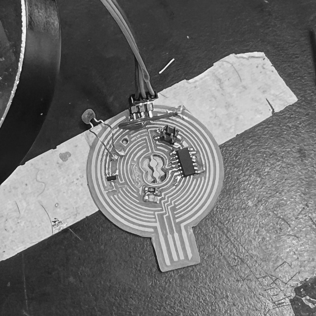
They gave me a different wire which worked out well. It was flexible so I had an easy time soldering it.
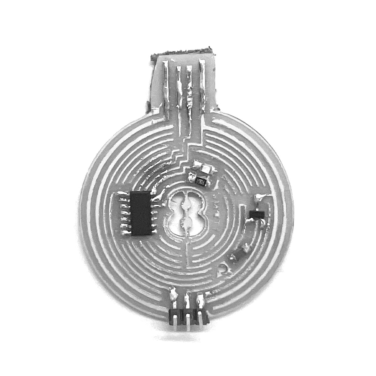
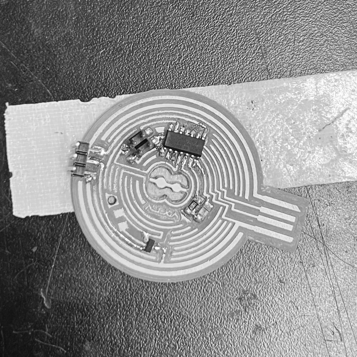
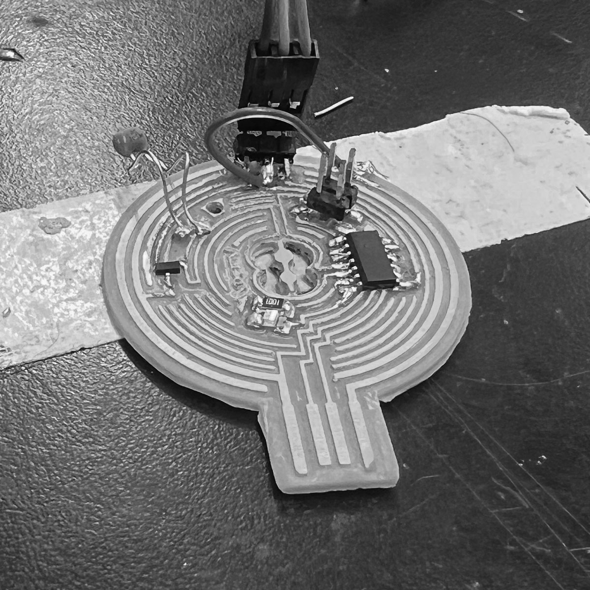
with everything soldered it was time to secure it
I covered everything in hot glue for safe measure
...except the processor and resistor
and that was a good thing
There was a moment were PK said they didn't understand why I kept trying and I just realized I didn't either
I would give it one last shot and then I had to move on somehow.
My heros came to help for this final attempt.
In trying to program we realized i put the processor on backwards. I went to fix that with a new one.
We realized my resistor wasn't outputting current. I replaced it.
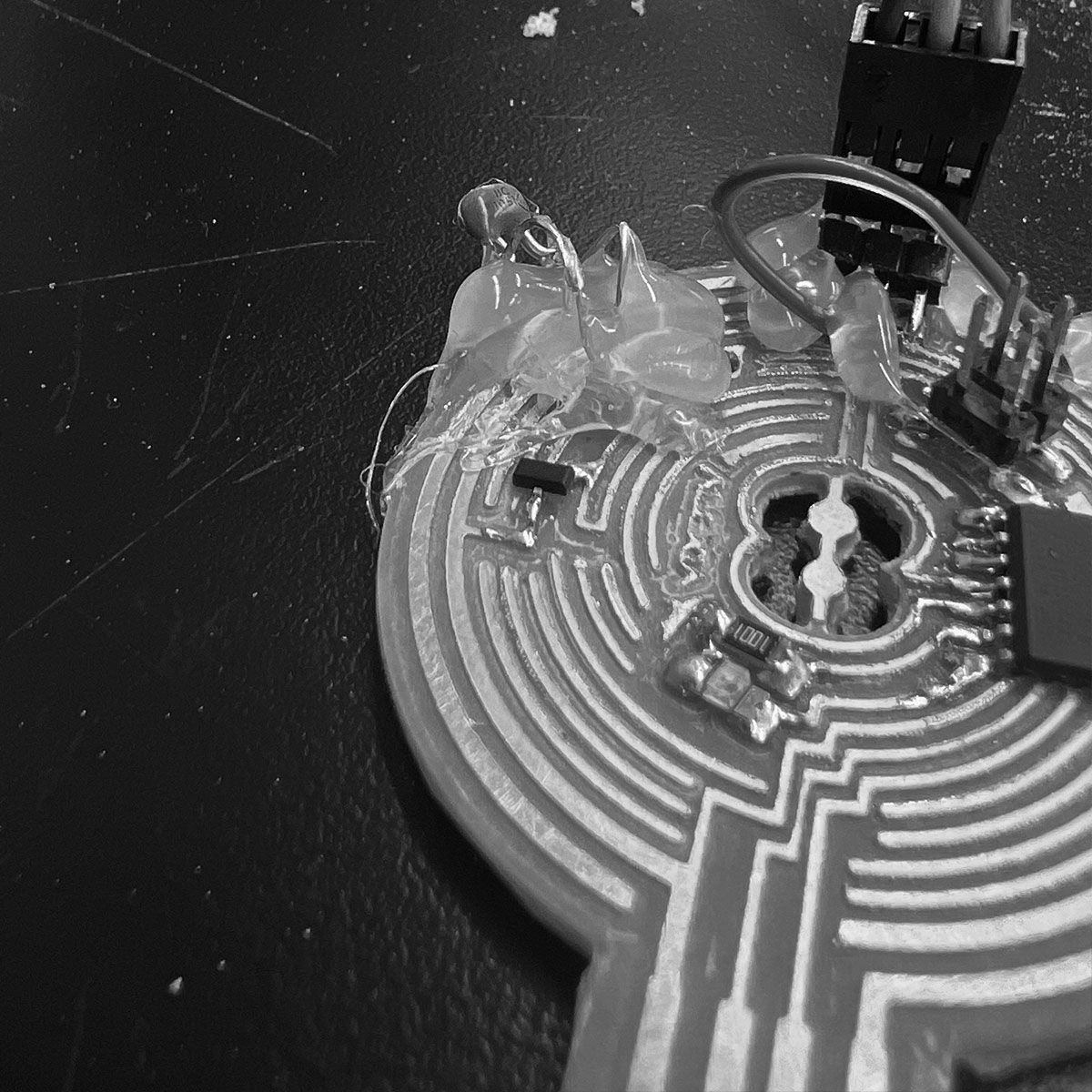
I corrected all shorts or missed connections found... still not working
hard to see if there were shorts under the hot glue so i melted/scraped some away.
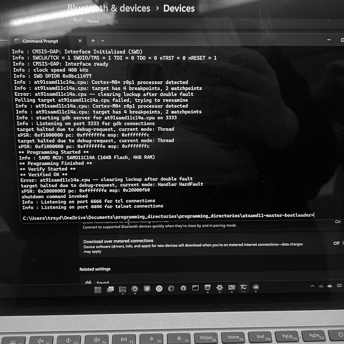
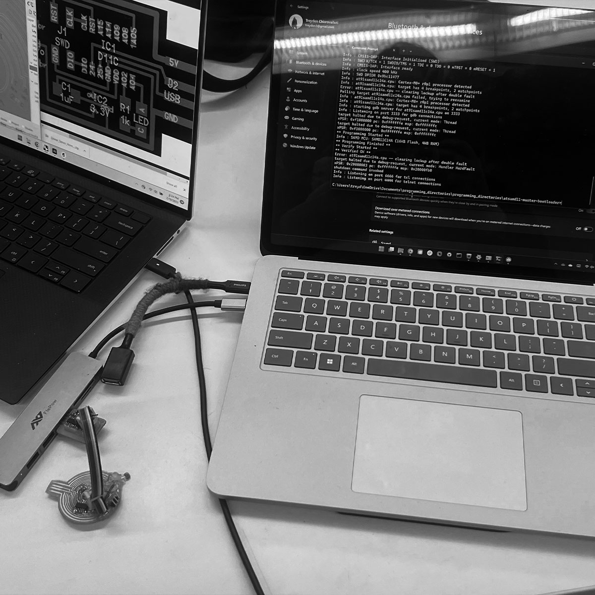
We were able to program the board (Treyden showed me a method via arduino with the new update).
But as Treyden pointed out to me, his usb hub was detecting a short in my board, neither of our computers was properly detecting my board and just because the processor pins are properly connected it doesn't mean other things are connected well.
After some time of going back and forth on solutions it was late. I turned to Treyden and asked to borrow a board with pins. I just need a signal, ground, a power (what i learned from the marble machine in machine week)
I really did try so hard to make a functioning board happen, consulted with multiple TA's and electrical engineers but I think it just wasn't meant to be. At the 10th board will the 11th be different? Oh well at least I can walk away with the knowledge of what it means to design a pcb but likley use an arduino or contract someone else to do it in the future.
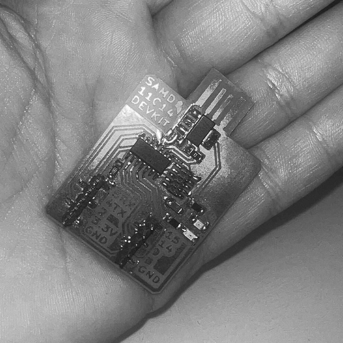
Thankfully Treyden had a board I could use.
I might have not succeeded at this one singular task of making my board function... but my project could still go on... and all it took was me realizing I needed to quit.
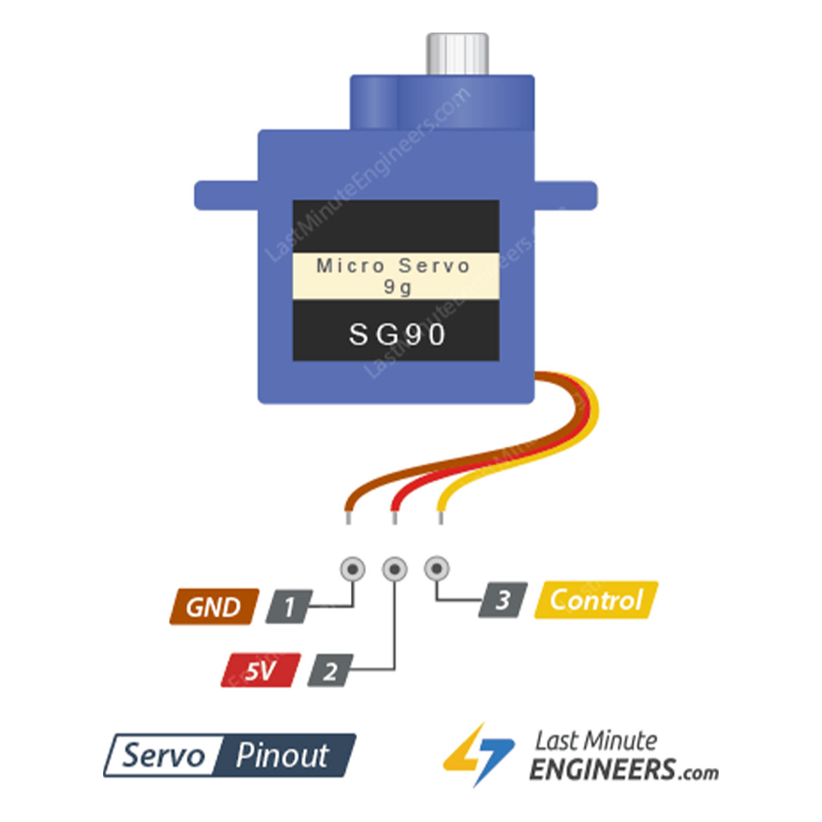
I used this pinout diagram and some additionally googled information to confirm the pins i should plug into on Treyden's board
I played with a simple arduino code I got off the fab academy website but of course I couldn't get the simplest script to work...
...or so I thought.
https://fabacademy.org/2020/labs/leon/students/adrian-torres/samdino.html#servo
I realized none of the ports were properly showing the board (something I couldn't realize to this point because I hadn't had a successful board and for some reason all my ports said SAMD11C.
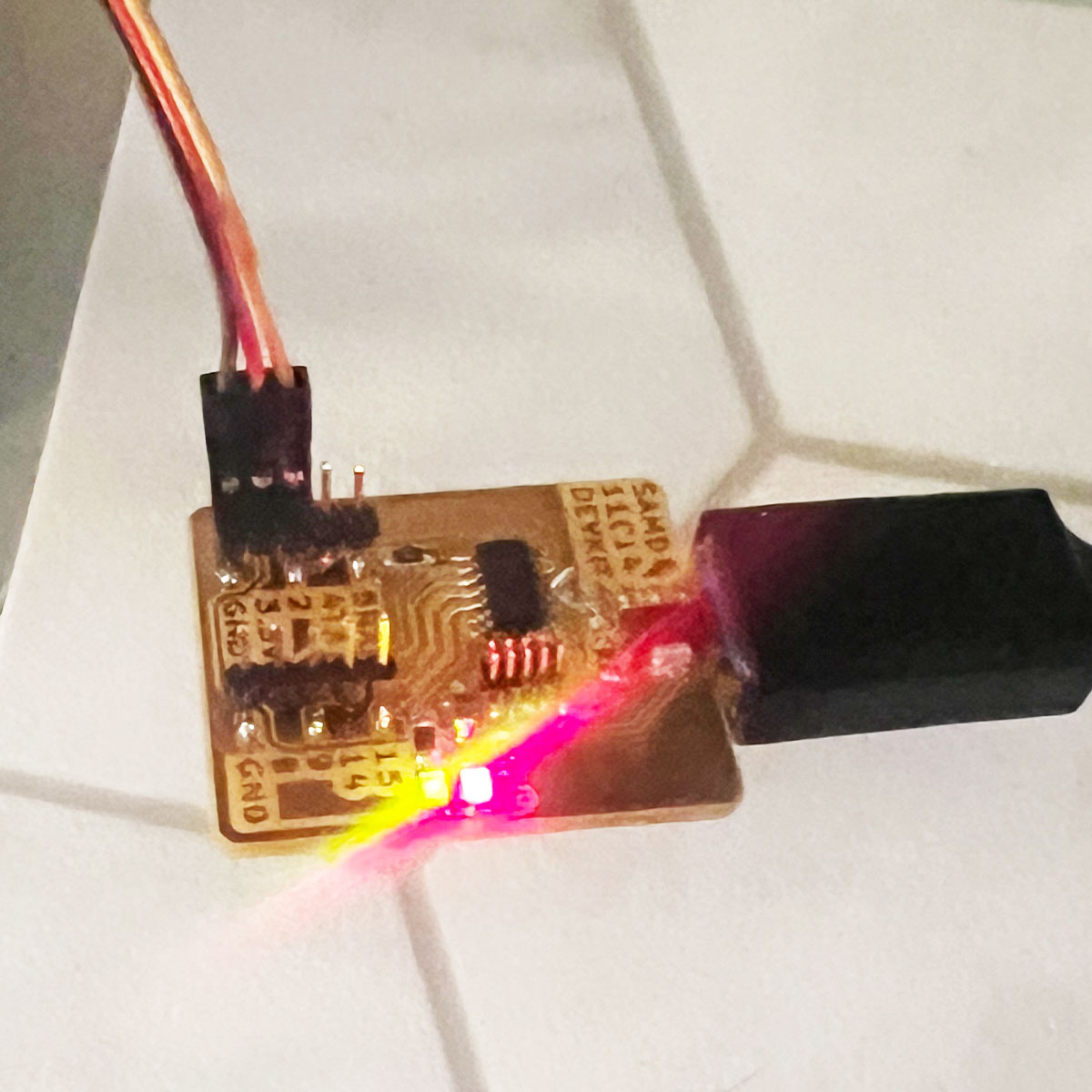
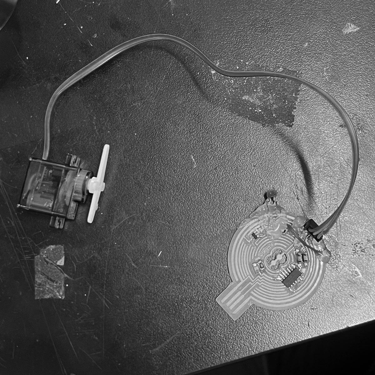
I gave it another shot switching out the usbc adapter and the board lit up!!! I plugged in the servo according to the pinout diagram.
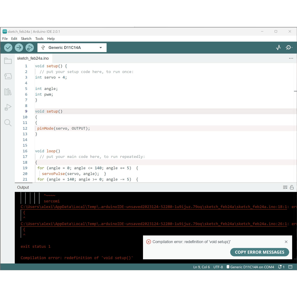
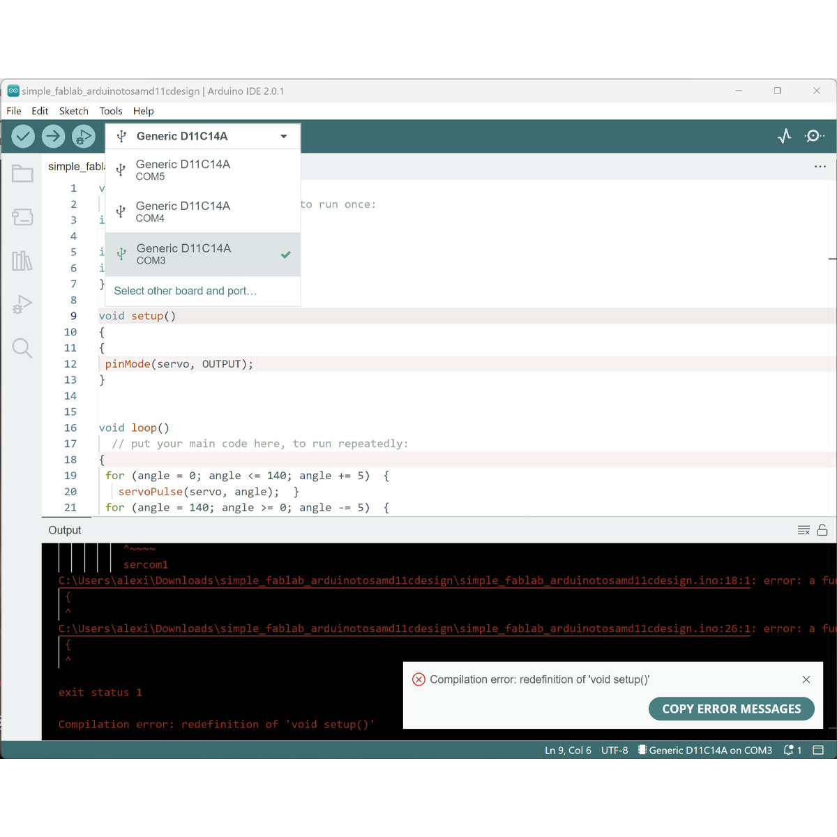
I set up the model and tested Arduino IDE.
Check my htmaa archive for the code./a>
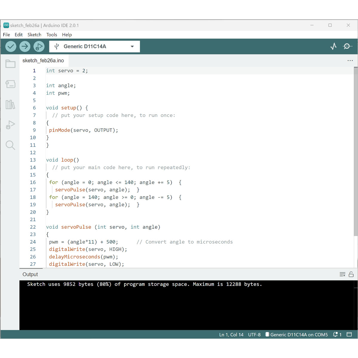
At first I had a mistake in my code that I quickly fixed.
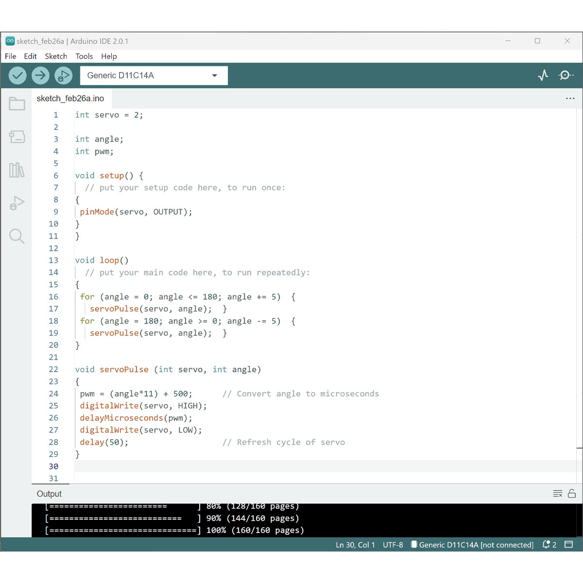
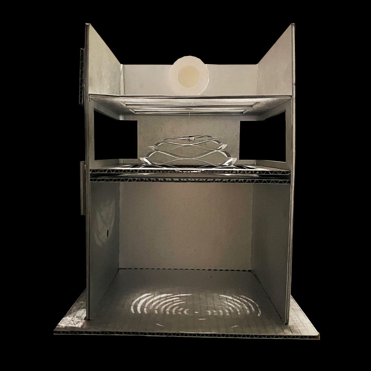
and with this bit of code the project was running!
The pulley was spinning.