Week 10: Networking and communication
This week, I made a new board and connected it to my phone via Bluetooth.
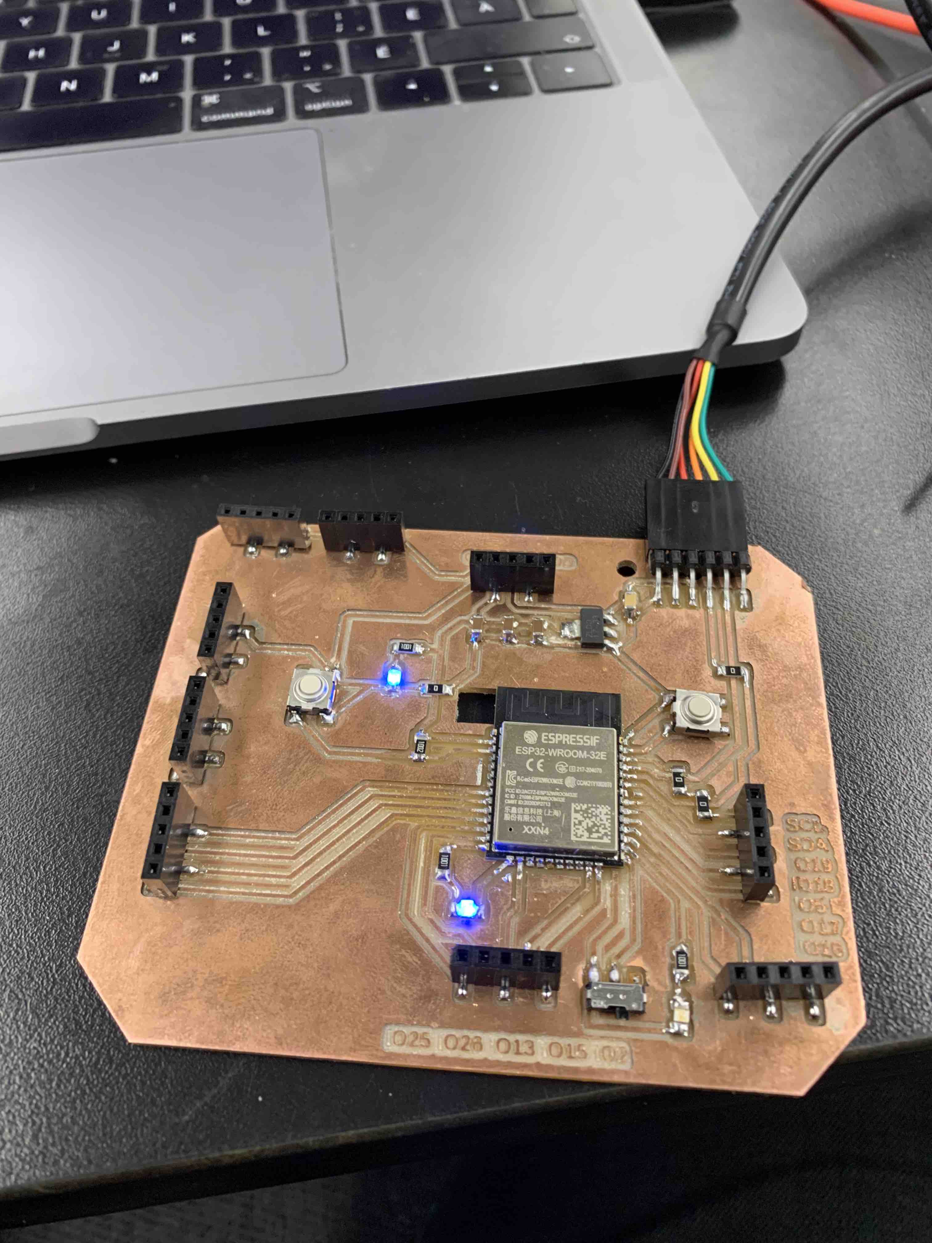
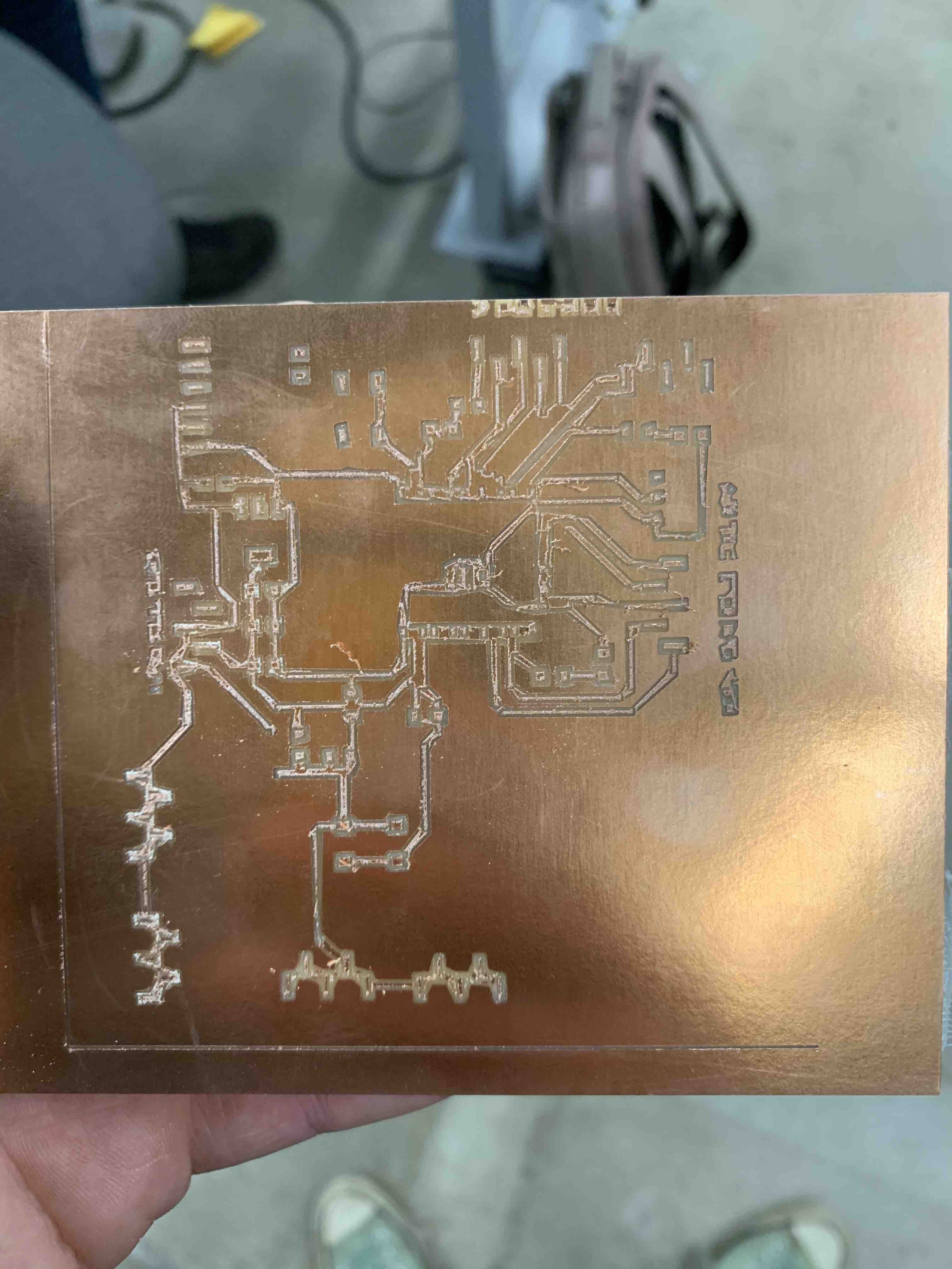
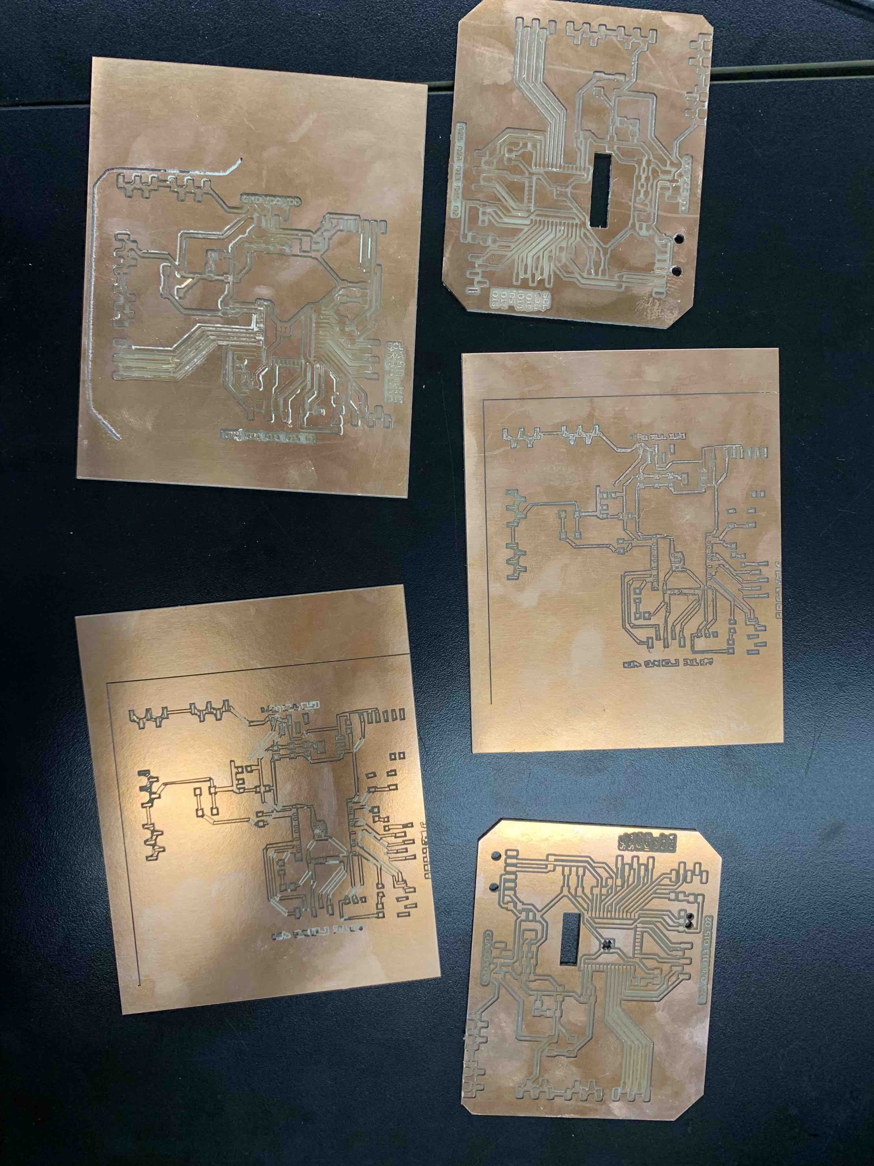
The first step was to build a new board with an ESP32 micro-controller. My goal for the week was to mill for the last time this semester. Time will tell...
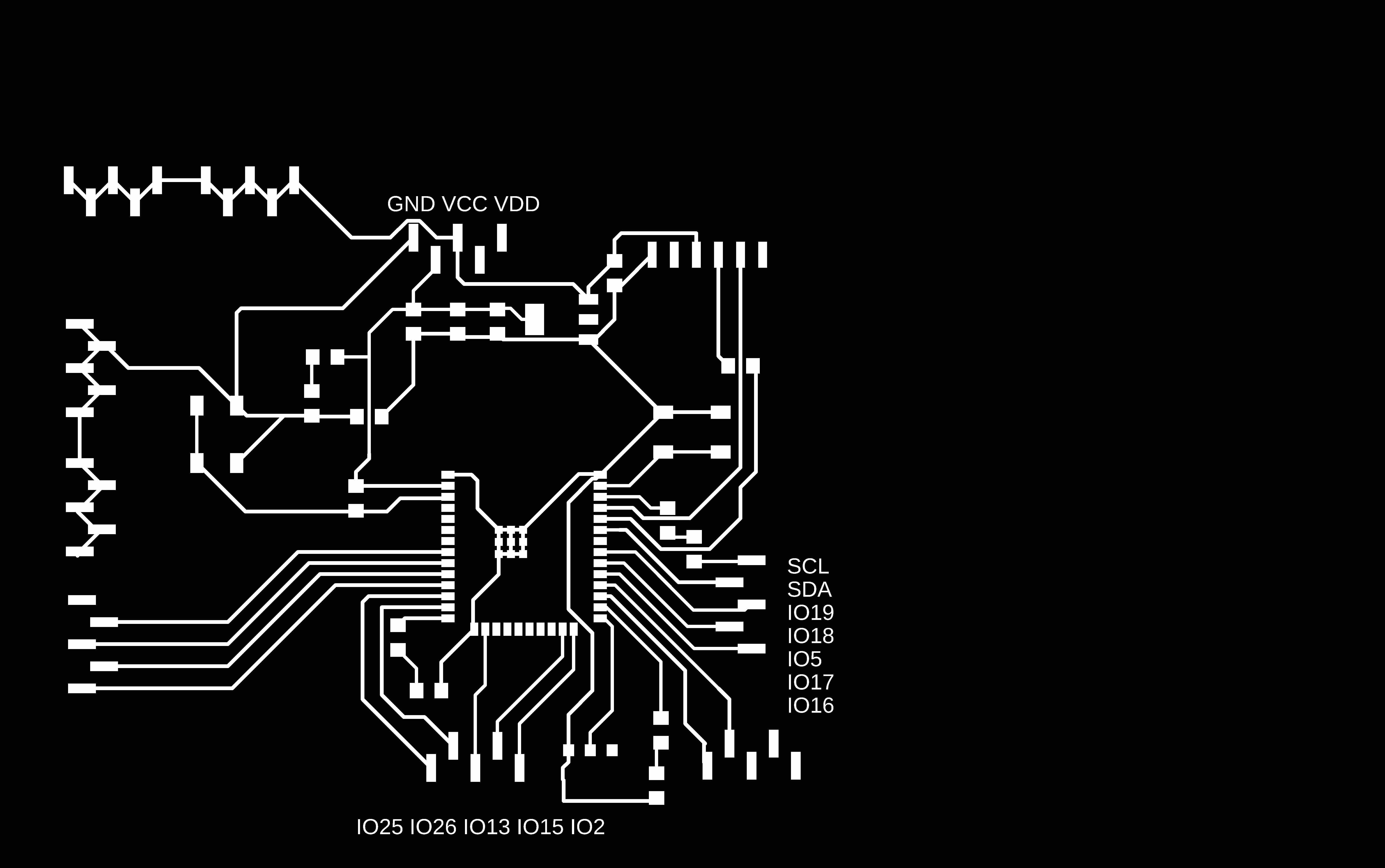
Once my board was schematized, I routed everything and exported the PNG files. I was ready to mill (and millI did).
As I was stuffing my board, I realized that a few pads were linked. I did some minor surgery on the board, using an exacto knife to separate the components. This worked well and I was able to quickly stuff my board.
Then came time to program it. To make my life easier, I bought a FDPI to USB interface on Amazon. I understand that I could build a USB interface for a dollar. However, I am still a beginner with electronic design and I have to cut corners where I can... Next time I promise to build my own one myself.
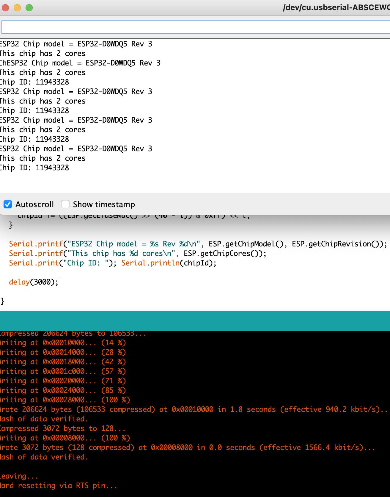
Programming the board ended up being a bit more complicated than I expected. First, I had issues with the Python version I was using with the ESP32 library within the Arduino IDE. I had to edit the library file through my Mac's terminal. This felt very sketchy, but worked on the second time. The problem was that my Arduino was looking for Python 3, but the library linked to Python 1
However, once this issue was fixed, I still was unable to communicate with my board. After an hour of trial and error, I realized that I had a hardware issue. Turns out that my board surgery had only been partly successful. I did a second pass with the scalpel and my board had a pulse. I was able to upload software!
Once I manage to communicate with my board, I followed the PS70 tutorial for bluetooth connection. Tweaking Nathan's code, I was quickly able to establish a connection between my phone and the board. Success, I turned on the LED with a phone command.
This doesn't sound like much, but I was very proud of that lit up LED.