Week 2: Electronic production
This week, I built a usb programmer. This was my first time milling, soldering and flashing a PCB. This week's assignment went pretty smoothly, and I only had a few bugs to fix. It was my first time working with hardware and software at the same time; I learned new fabrication and debugging techniques/
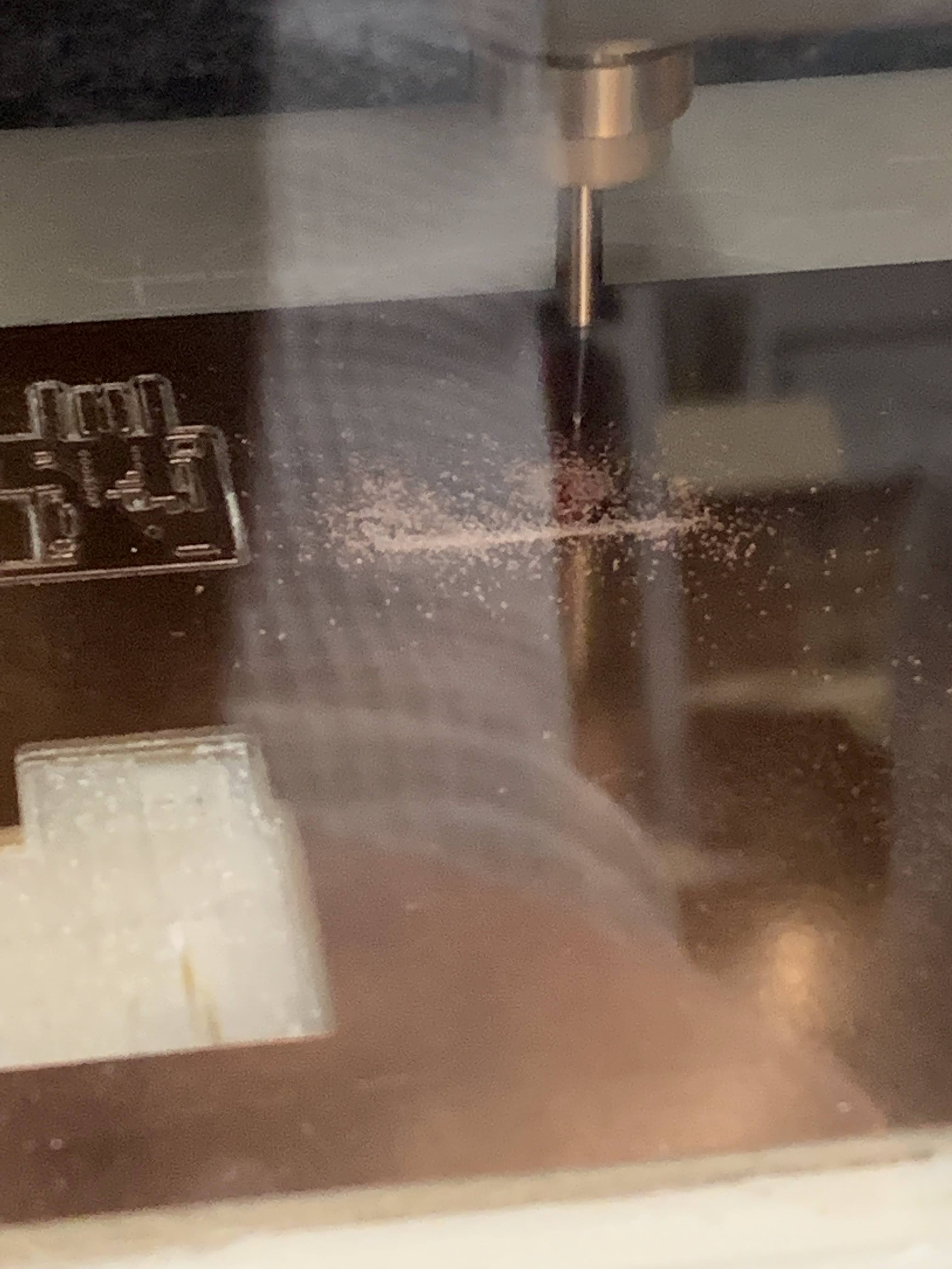
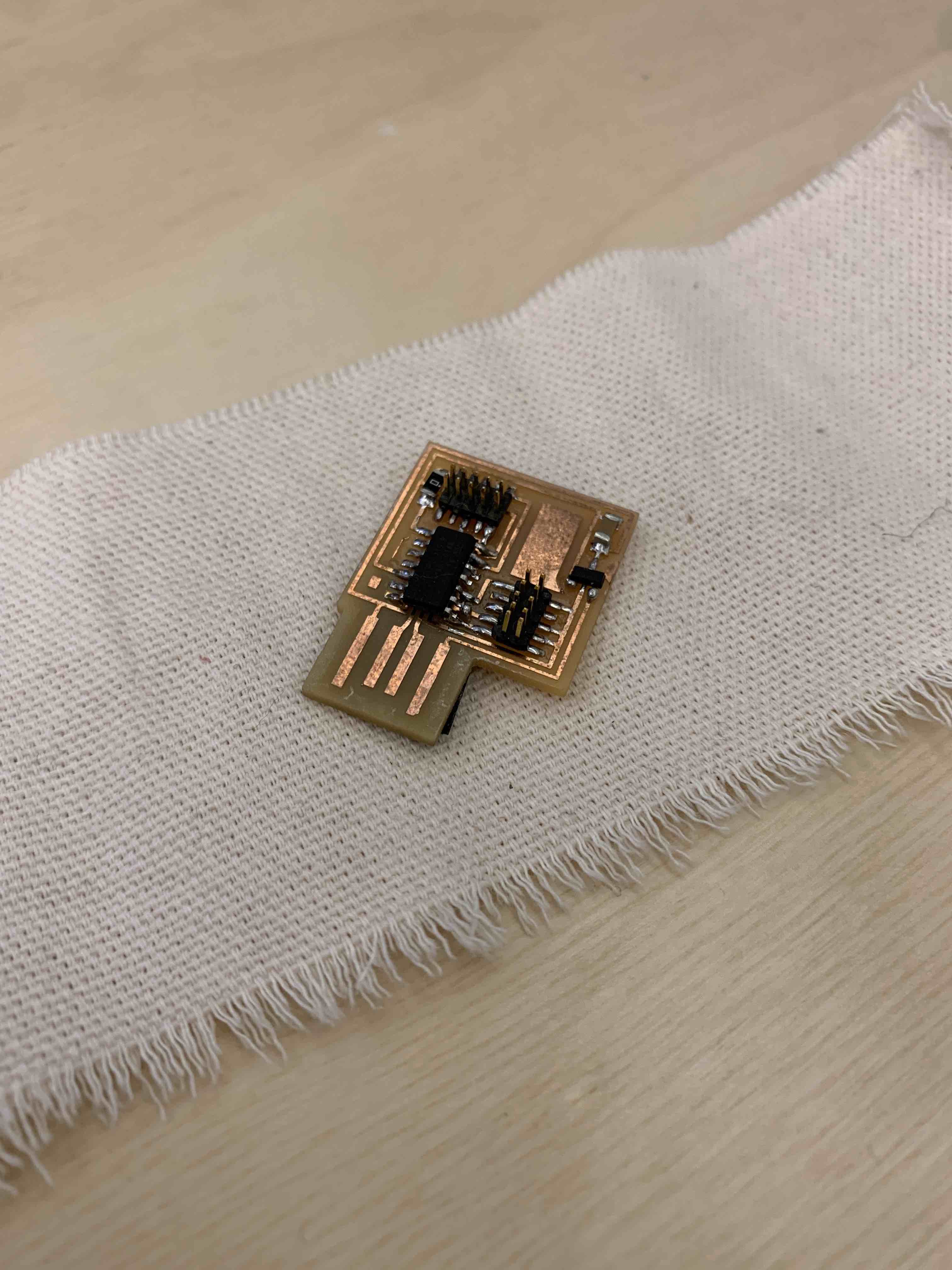
first step was to mill the board. I used the SC 102 milling machine. The process required a 1/64th and a 1/32nd bits used on a copper plated board. For this project, I used the two provided PNG files which had the engaving and the outline of the board.
I was able to mill my board on the first try. However, the above picture represents an instance where the milling of a classmate failed. In this case, the bit was not set up close enough to the copper board. As a result, the machine failed to engrave the copper (the bit hovered over the metal).
I then soldered all required components to the board. This was my first experience soldering and I was appréhensive. Nonetheless I picked it up quickly and was able to solder my board. Trying it help me understand what Neil meant by "the solder will flow along the copper".
I did have to resolder some components. For instance, I soldered the micro-controllet backwards and had to resolder it in place. I used the copper braid to remove the solder.
This process was pretty straightforward. I was able to salvage the component and stuff it in the right way. I learned to use a lower temperature for the iron in order to make sure that it would not remove the copper lining of my board.
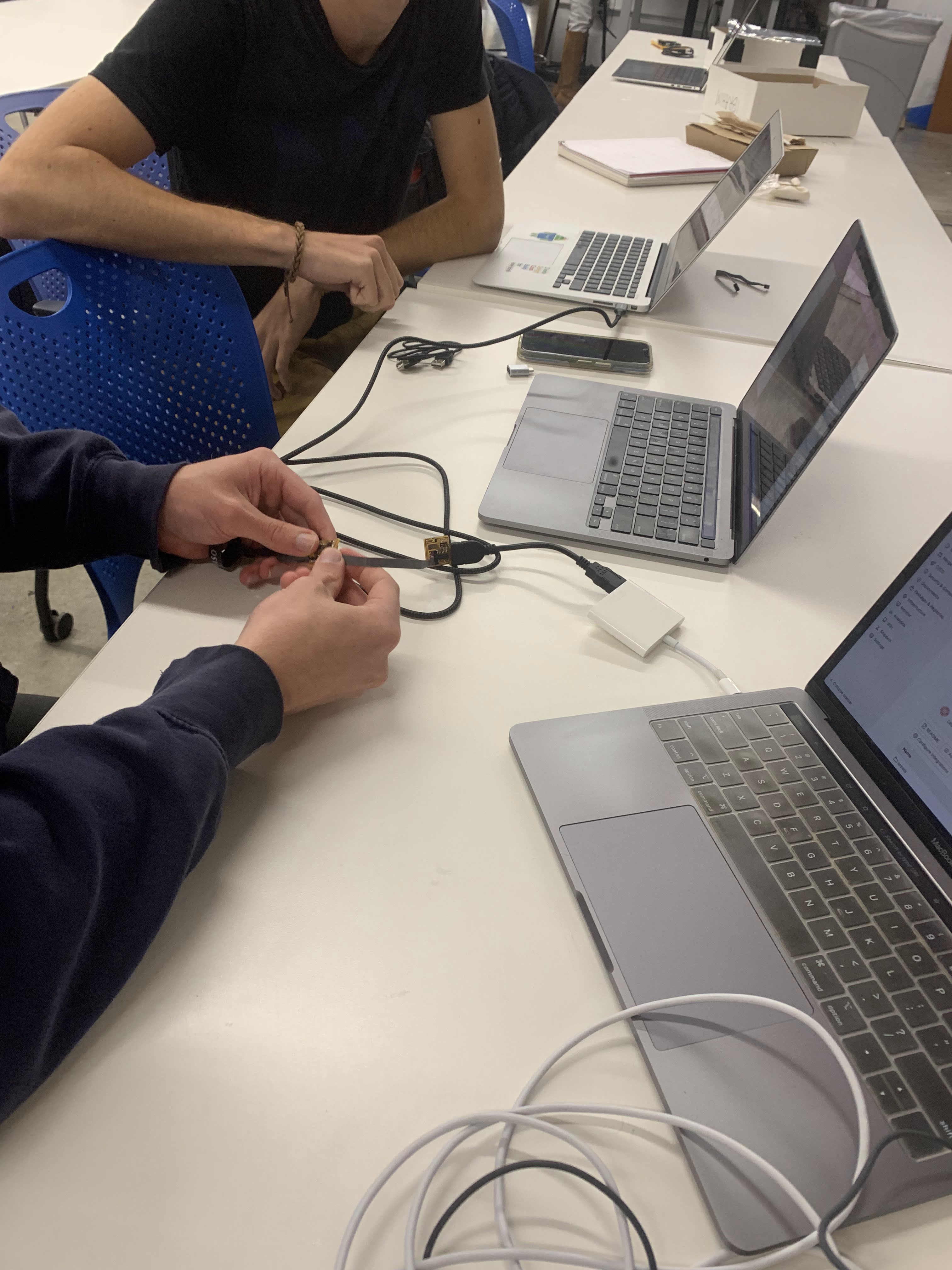
I then programmed the board with the help of Leo. He assisted me with the debugging of the hardware. I learned to identify a false connection of the usb port and to assess whether the board could get power.
As I was flashing my board, I realized that there was a short in my board. I used the voltmeter to identify the issue. I then resoldered the faulty connection to fix the bug. After that repair, I was able to load the board and program other boards.