Week 4: Electronic Design
For this week's homework, I designed and built a PCB ioncluding a light and a button. I learned to use Autodesk's Eagle, building schemtics and tracing circuits. This is a muscle I need to develop, but I feel like I am on the right path.
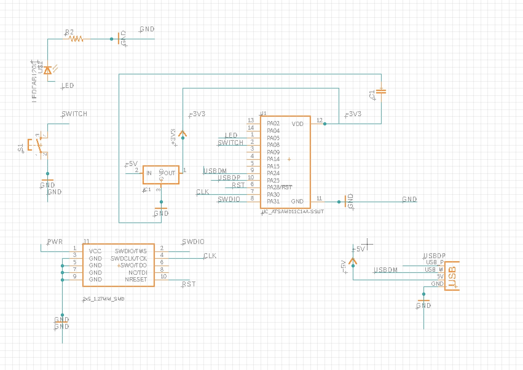
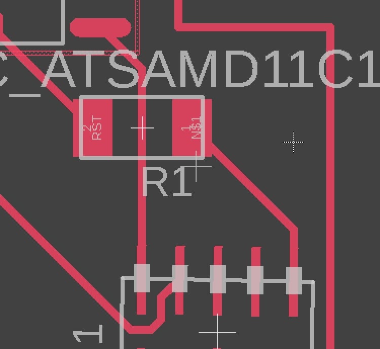
The first step of the process was to design the board in Eagle. I started with a diagram view of the system.
To understand the role of each component, I worked with our TA and looked at precedents from previous years This helped me understand the role of components and how to use them in a circuit.
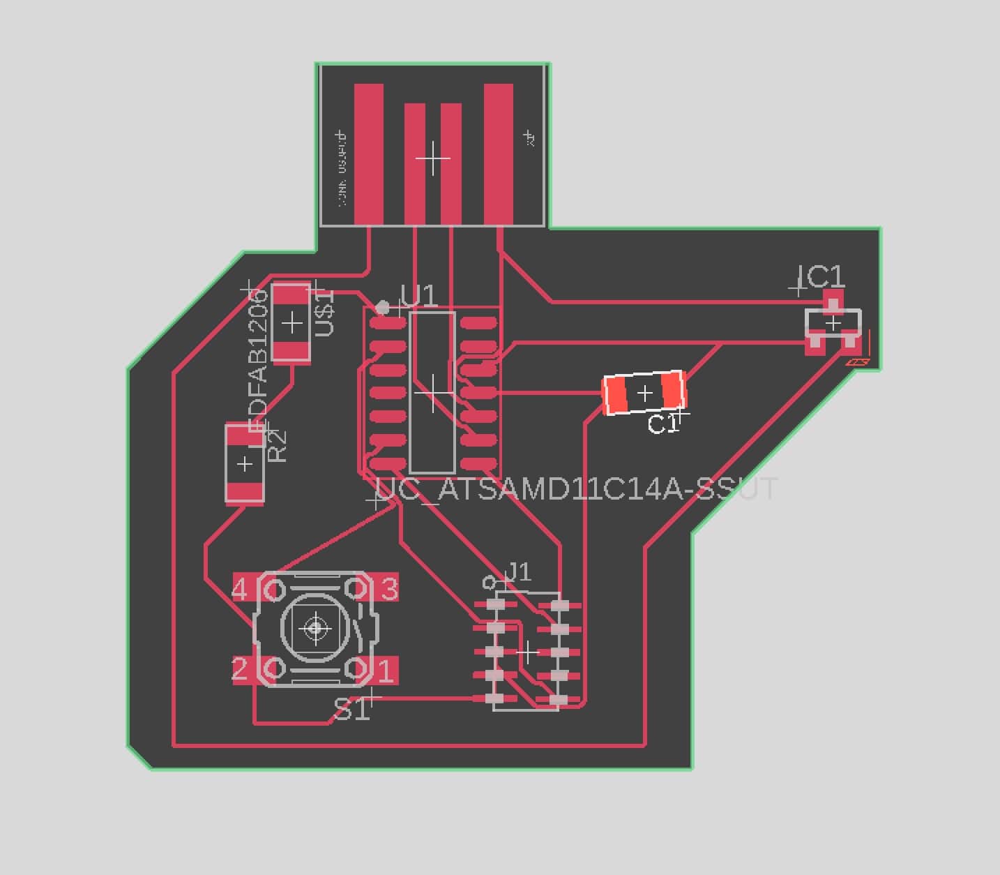
I then worked with the layout tool to position each component. This was quite challenging at first as I couldn't figure out how to make sense of the components.
After many tries, I realized that it was easier to start with the components that "had" to be connected in a certain way and to work from there. Namely, I started with with the 5V cable around the board, the USB data plus and the USB data minus.
From there, I wired the rest of the connectors. I had to use two 0 ohms resistors to jump over cables. I chose a compact design, hoping to make my board as small as possible.
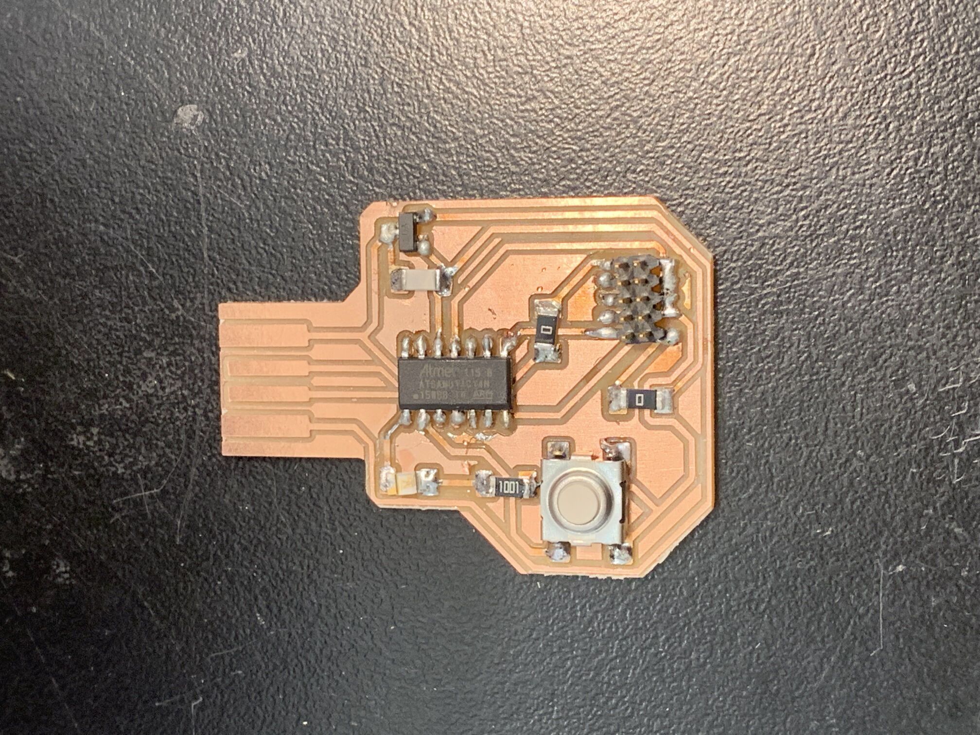
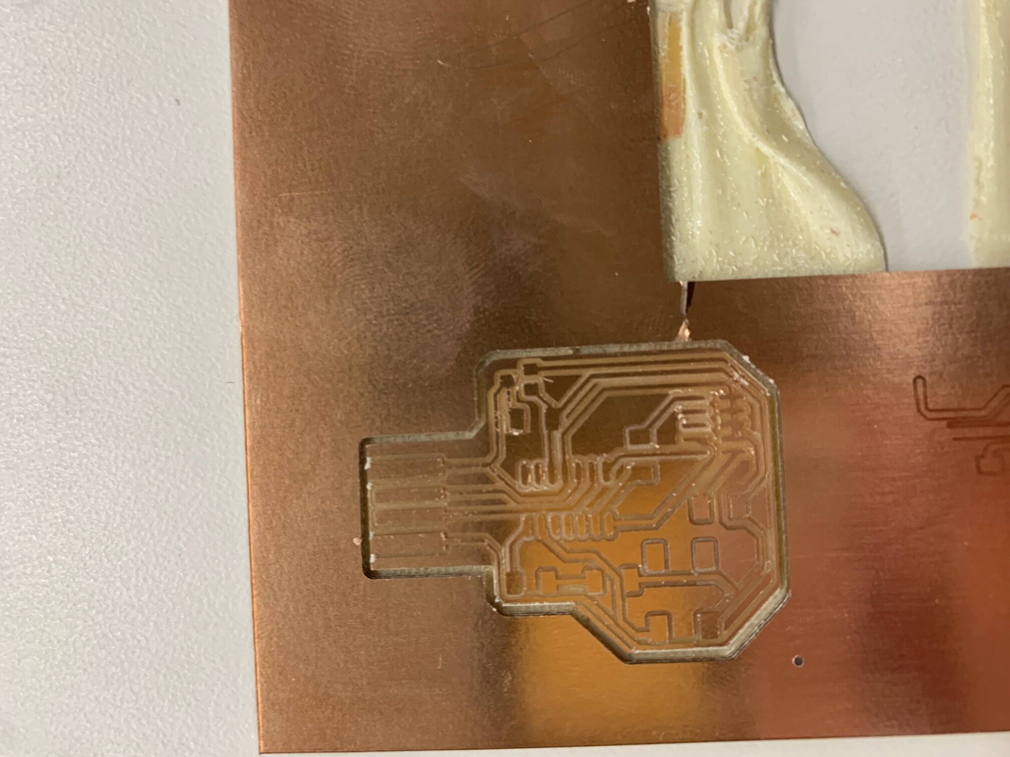
I then milled the PCB. Other students encountered issues with the machine. However, I was able to print it on the first try.
Nonetheless, I had some small software issues. I had some problems with the upload of the outline png to mods. I had to add an inside trace in photoshop to make sure that all my traces were recognized.
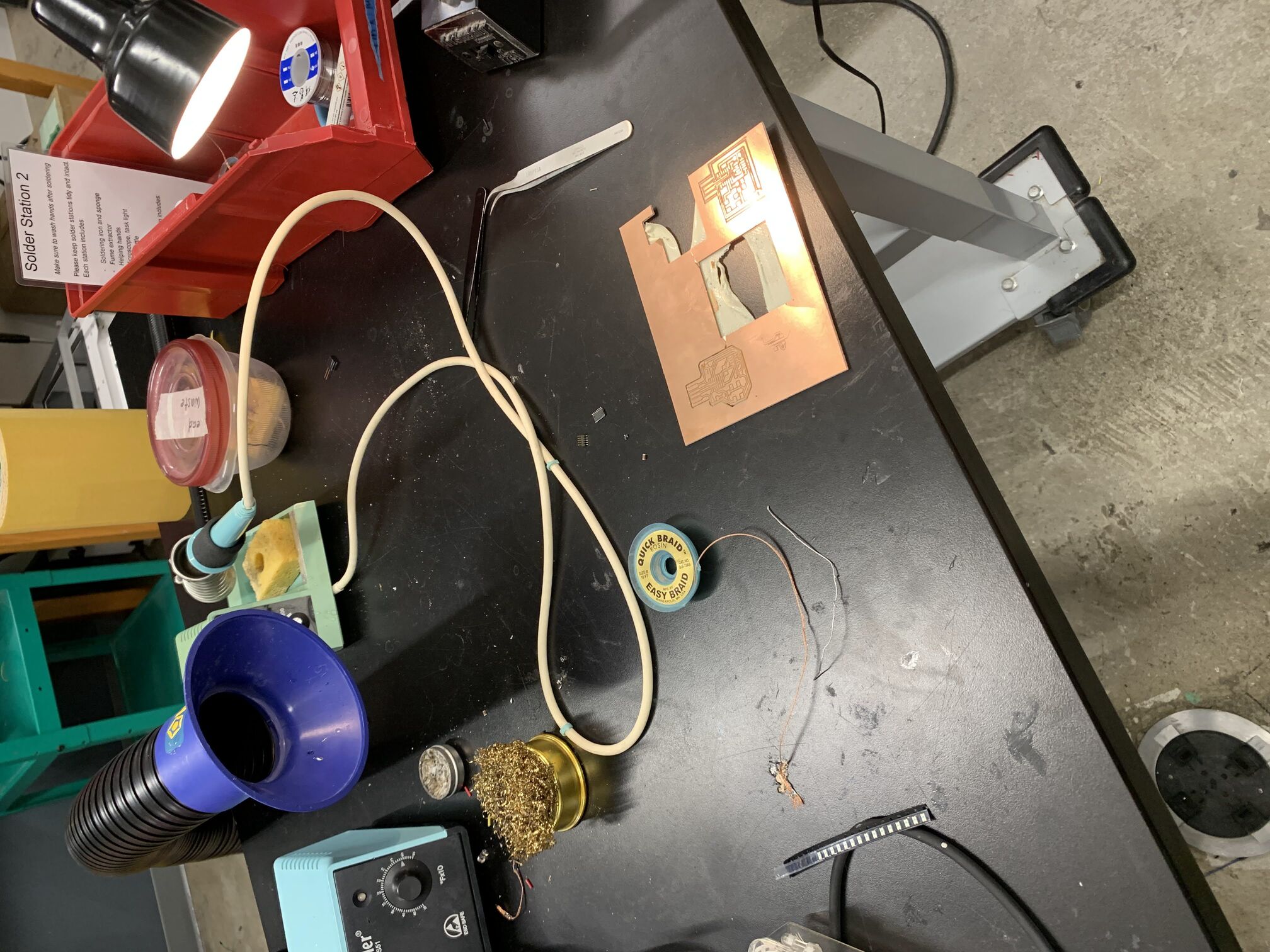
Finally, I soldered the components on my board and booted it.
Unfortenately, the programmer I built a few weeks ago stopped working. I had to use the TA's programmer to flash my board.
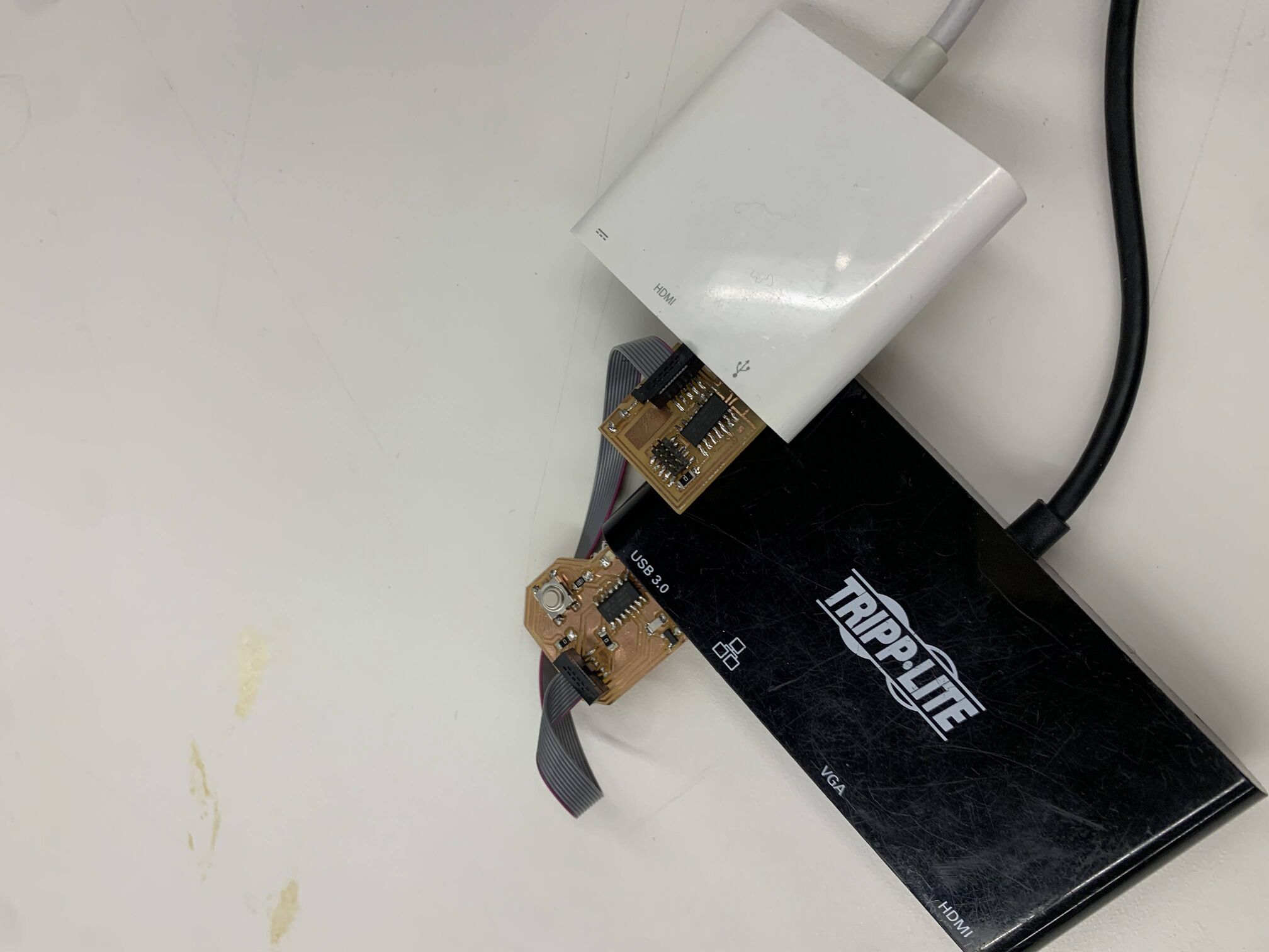
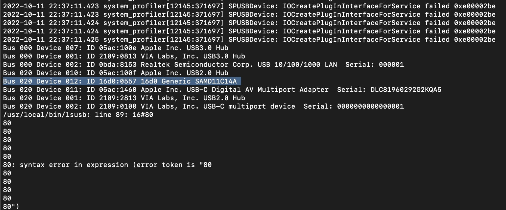
Succcess! My board was recognized by my computer. Next step: programming!
I will take on that challenge in two weeks. I plan to start with the onboard LED, but to also build a new board that will be part of my Halloween costume. Stay tuned!