Week 9: Output devices
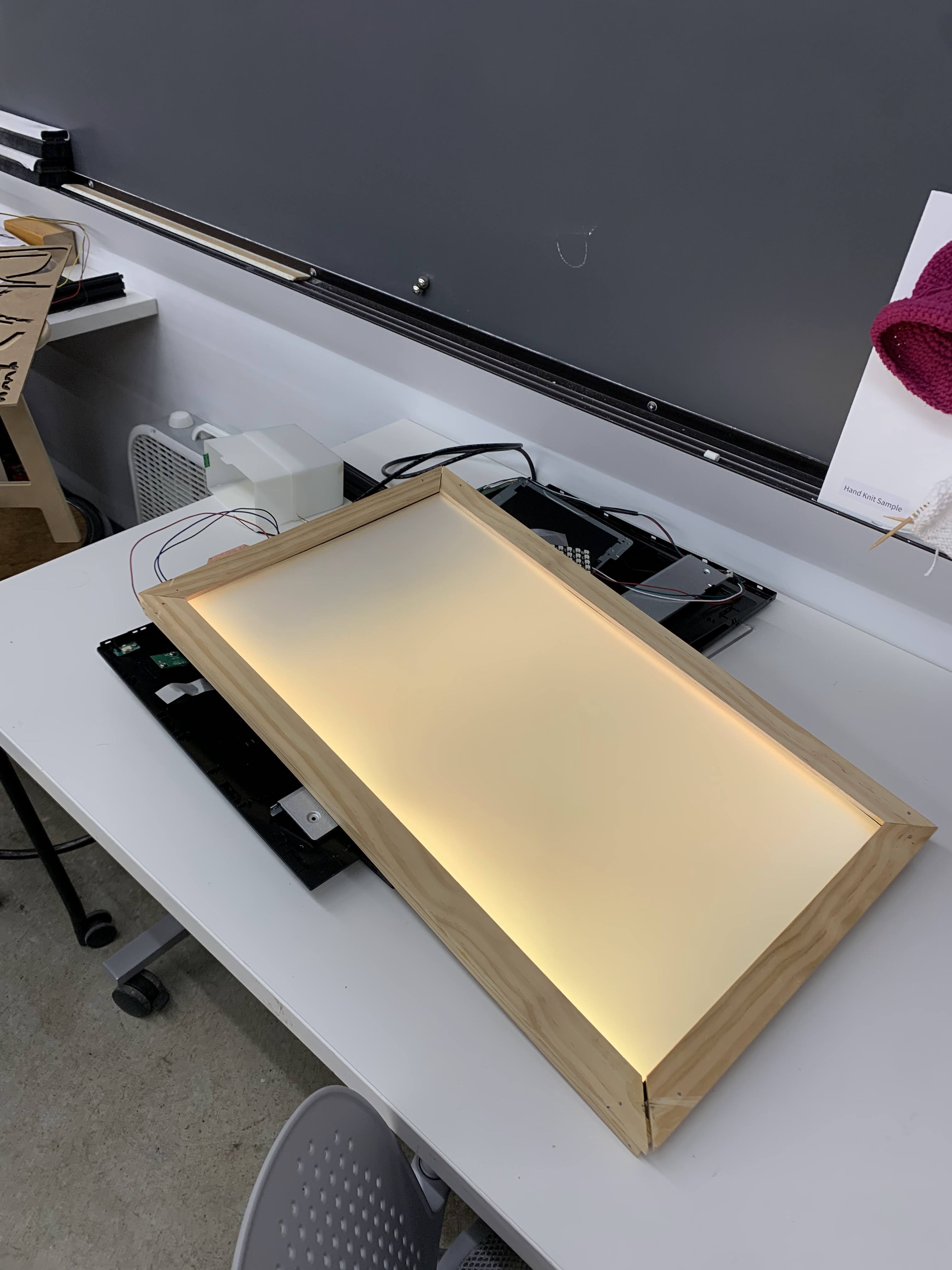
This week, I built an artificial skylight with addressable LEDs and a broken computer screen.
My work was inspired by the work of DIY Perk, a youtuber who shared a video explaining the underlying idea. The concept behind the project is to repurpose the refractive and diffusive layers of a backlit LED screen. I used my classmate's broken screen and a strip of dense addressable LEDs to bring this project to fruition.
The first step was to find a way to light up the LEDs. I thought this would be simple; I could easily re-use the PCD I had built for my Halloween costume on week 6. Or so I thought....
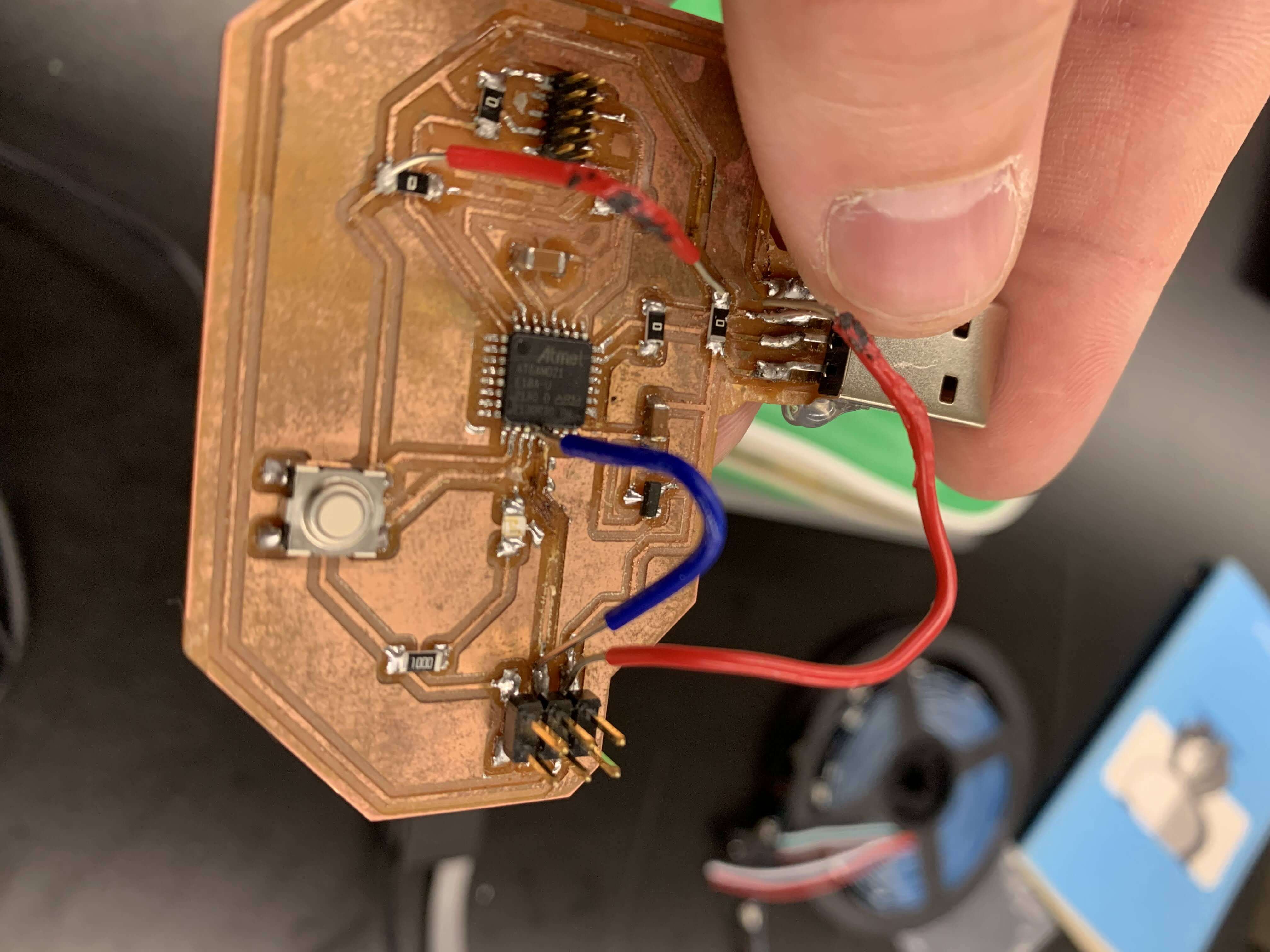
To investigate the issue further, I measured whether I was able to send voltage to the power pins of my 6pin connector. However, the voltmeter I used returned erratic readings oscillating between "too low" and 0.1 V. To investigate the possibility that I had fried a pin of my SAMD21, I soldered a jumper wire to a new pin of the processor. I also tried to wire the LED strip to an external power supply (only getting data from the PCB). To my despair, nothing was going through.
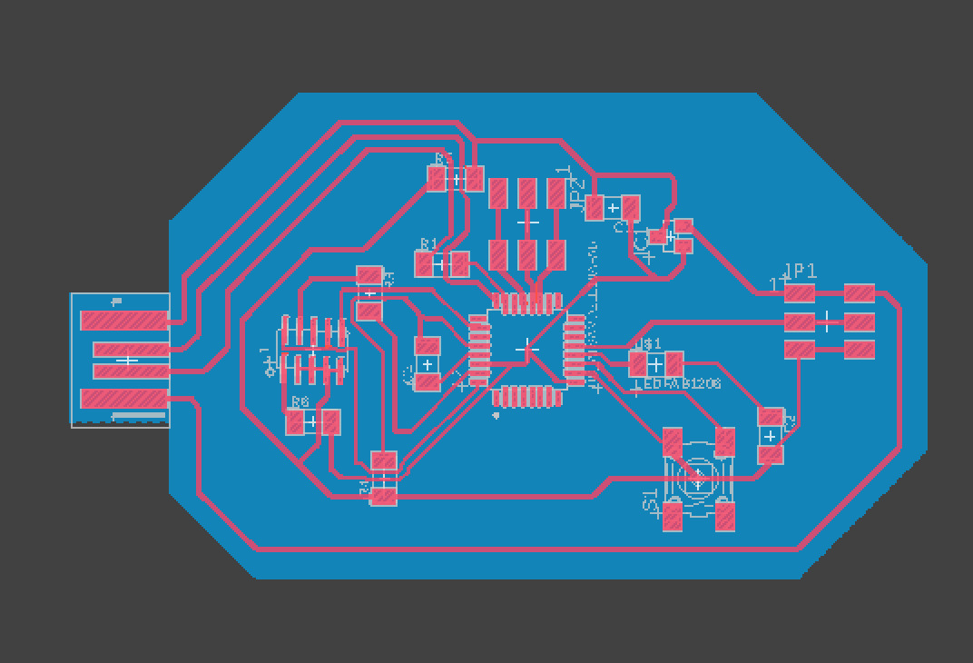
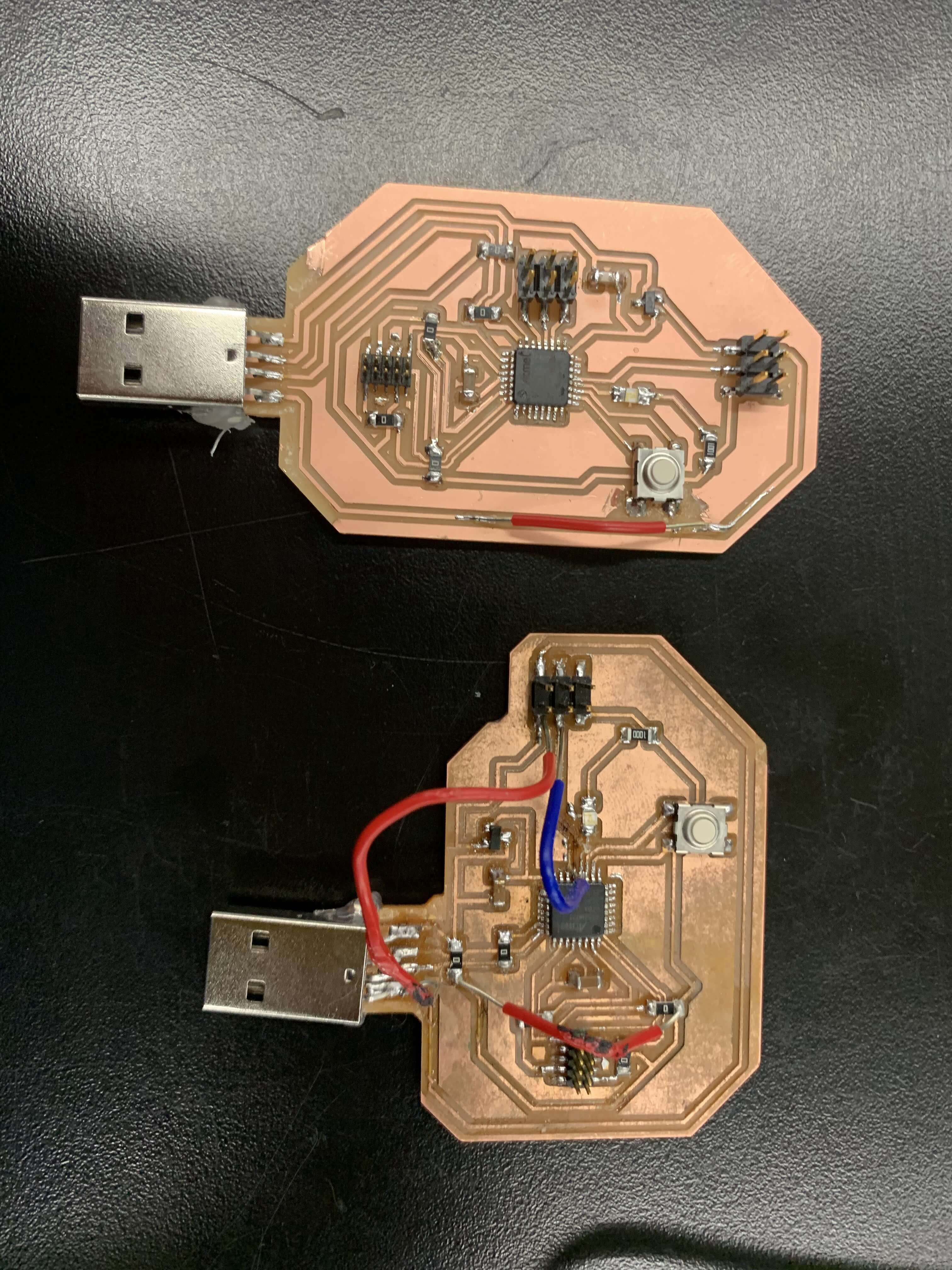
To fix the situation, convinced that my PCB was broken, I milled a new board. I used a slightly modified version of the PCB from week 6. I just changed the position of the USB port and added 3 data connections from the SAMD21. The milling and stuffing process went smoothly. 2 hour later, I had a new board bootloaded and ready to go.
Though, my troubles were not over. Even with the new board, I was unable to get any signal to the pins. The oscilloscope and the voltmeter were of no help. I then called for help and Quentin, my TA, came to the rescue. We spent a few minutes looking at the code, trying to figure out what was wrong. After a trip to GitHub and a few forums, we confirmed that the chipset was supported.
At last, I discovered what the issue was. Actually, there were two issues: 1) the setting of the Arduino IDE were not properly set up, 2) the voltmeter I was using was not reading correctly. Once I had selected the right chip version (SAMD21E18a), I was in business. I learned more about the Arduino IDE and measurement equipment. Oh, and I guess I have two working boards now.
Once I fixed this issue, I could go forward with the project. I started by connecting the new LED strip and using the NeoPixel library to get the lights going. My goal was to cycle through colors at the push of a button. I thus coded a counter loop leveraging the onboard button of my board. My classmate Tyler helped me with the code. I implemented a few variables and experimented with the serial output. After a few minutes of debugging, I had a reliable button.
I chose 6 colors to cycle through for the final design. I implemented them all using the NeoPixel library; my code and hardware were ready.
I then started to disassemble the computer monitor, following instructions had found online. I removed all electronic components and saved the acrylic and plastic layers of the backlit screen. I had to use a dremmel to alter the metal frame. I also removed the legacy LED strip of the screen and glued the new WS2812b strip.
An issue I encountered is that the new LED strip was much thicker than the old one. I used cardboard to build space between the LED and the acrylic layer and assembled the unit using the original order of the screen.
Once I had set up the screen, I was able to get a refractive effect and to cycle through colors. However, the refractive effect was not has potent as I would have hoped. The DIY Perk video had a much better result. In any case, it was a cool result that I can use in my living room. I finished the project by building a wooden frame for the setup. Overall, I'm happy with the final result and will use it for ambient lighting. Only next step would be to build a case for the PCB.